Conceptual design in the automotive industry is a time-consuming process. Iterations .... is that the employed interaction paradigms require training and make an ..... closest to the original (before the modification) target curve. Using our model ...
EUROGRAPHICS Workshop on Sketch-Based Interfaces and Modeling (2007) M. van de Panne, E. Saund (Editors)
Example-Based Conceptual Styling Framework for Automotive Shapes István Kókai1 , Jörg Finger1 , Randall C. Smith2 , Richard Pawlicki2 , Thomas Vetter1 1
Departement für Informatik, Universität Basel, Switzerland 2 General Motors Research and Development
Abstract Conceptual design in the automotive industry is a time-consuming process. Iterations between concept sketches, created with traditional two dimensional methods, and 3D digital representations of a prototype are currently one of the big bottlenecks. In this paper we present a framework for an integrated 2D-3D design environment. The core of the framework is a model representing the characteristic lines of automotive shapes built from a set of example shapes. From every example shape we extract the same set of characteristic lines and represent them with a feature vector of deformation gradients. Given a set of constraints, our method can generate a new feature vector with an optimization procedure. We provide examples for meaningful manipulations. We demonstrate that these manipulations are intuitive and create plausible shapes. Categories and Subject Descriptors (according to ACM CCS): I.3.5 [Computational Geometry and Object Modeling]: Curve, surface, solid, and object representations
1. Introduction In the automotive industry, most steps of the design cycle have been digitized. Yet, in the very early phases of conceptual automotive design, traditional methods like 2D sketching prevail due to their intuitive and explorative nature [Sin06]. Despite tremendous progress in CAD and computer graphics, there is still no product that could satisfy the designers’ needs for fast and intuitive exploration of ideas which could lead to a successful concept design. Most tools get in the way of creative thinking because they are tailored more for representing ideas which are already almost complete. The traditional styling process, where concept sketches are developed in two dimensions and a three dimensional representation is unavailable until many weeks later [TO00], is one of the causes for long development cycles in the automotive industry. Even small changes to the concept model can be cumbersome and could require starting over with the styling process. It would thus be a great improvement to combine the intuitiveness and ease-of-use of the traditional sketching with three dimensional digital modeling tools. Many approaches have been proposed in recent years to c The Eurographics Association 2007.
solve the above problem. We provide a review of the related literature in section (2). Ranging from new input methods to the problem of understanding 2D sketches and converting them into 3D, these applications make conceptual design more accessible. Yet, the lack of methods for rapid and intuitive exploration of different possible designs are limiting their widespread acceptance among designers. This work introduces a styling framework for automotive shapes that leverages the domain knowledge of existing shapes and provides intuitive modeling possibilities that support the explorative nature of early conceptual design (see figure 1). The proposed method uses a set of example shapes to define the design space, and generates models which are close to that space without being too restrictive. We developed a representation that resembles 2D sketches but is internally based on a set of carefully selected 3D lines, which allows the viewing and manipulation of the model from different viewpoints. The set of lines is motivated by research on automotive design sketches. Tovey et al. find that so called form lines are the most important in describing 3D form and appear earliest in a sketch [MTN03]. In our proposed workflow, the designer starts with a 2D rendering of a 3D model
I. Kókai, J. Finger, R.C. Smith, R. Pawlicki, T. Vetter / Example-Based Conceptual Styling Framework for Automotive Shapes
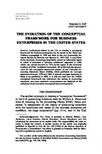
Figure 1: Using a set of example shapes (the two rows at the top), converted into a consistent representation, we build a deformable line model (represented here with the average shape at bottom left). With a set of constraints we can generate novel shapes (bottom right).
which is either provided by the system, or created from a set of sketches or blueprints. The presented framework makes the exploration of design ideas intuitive and fast. Interaction is possible with dragging points of the shape or oversketching. The visualization resembles traditional sketches, and shows the characteristic lines. During the editing the designer can change the viewpoint. Our representation is built from a set of user-provided example shapes. They are first converted into a consistent form. We define a mapping function, based on local deformation gradients, to project the examples into a feature space. Deformation gradients [SZGP05] provide a feature representation that is local and translation independent, and as such it is capable of capturing the local shape characteristics well. We describe an optimization framework to search that space for suitable solutions representing the constraints from the user. 2. Related work In his case study on conceptual automotive design, Karan Singh motivates an interactive approach for shape modeling. He lists a number of general desirabilities for a system that could support the creative process of industrial stylists and designers. While abstracting from the underlying math, the system should invite creative exploration and leverage domain expertise [Sin06]. In their study on automotive design sketches, Tovey et al. support the view that interactive exploration is central to the creative process. They state that, rather than depicting already finished mental concepts, new designs emerge through the sketching activity [MTN03, TO00].
In recent years much work has been done to develop tools that make working with 3D shapes more intuitive and accessible than traditional CAD techniques. A number of systems for working on 3D surfaces in a virtual environment with new input devices have been proposed [BLMR03, FdAMS02]. Grossman et al. constructed a system to create principal 3D curves with a technique that mimics the tape drawing method used in the automotive industry [GBK∗ 02]. One common problem of the above methods is that the employed interaction paradigms require training and make an intuitive and precise manipulation of the 3D objects difficult. Tsang et al. describe a system where users can draw on 3D planes [TBSR04]. The process for sketching the 3D models is fast and intuitive, but the requirement to draw curves on 3d planes can be too restrictive, because characteristic lines of industrial shapes are seldom planar. As designers mainly start working with 2D drawings, a considerable amount of research has focused on creating digital sketching tools. Interpreting 3D shape from 2D input is an ill-posed problem. Prior knowledge about the type of input or the object class is necessary. Some approaches derive a 3D object from its 2D silhouette [IMT99, KHR02, KH06]. In these systems the user draws lines depicting contours or cross-sections of the intended object. The lines are inflated to create 3D geometry. Various modeling operations, like sweeping, extruding, bending, can be applied on the resulting surface. While these systems are capable to quickly create reasonable shapes for simple roundish objects, like cartoon characters, they are not suitable for industrial design. In template-based methods, a 3D template is deformed to represent the users intentions. The complexity of the temc The Eurographics Association 2007.
I. Kókai, J. Finger, R.C. Smith, R. Pawlicki, T. Vetter / Example-Based Conceptual Styling Framework for Automotive Shapes
plate varies among the different approaches. Mitani et al. use a topology equivalent to a cube [MSK02]. This restricts the representable object class to simple objects. Yang et al. use 2D templates to recognize hand-drawn sketches [YSvdP05]. Their system works well if the drawing has the same viewpoint as one of the templates in the database. In a framework specifically designed to represent automotive shapes, Tano et al. uses a simple flexible template [TKN∗ 03]. The models created with this method are still inferior to the quality reached with pen and paper. More elaborate templates are used for creating 3D objects by Kara et al. [KDS06, KS07]. Their method is capable to create high quality models, but the requirement to edit each curve separately makes the rapid exploration of different designs difficult. Learning an object space from example shapes provided by the user is not a new notion. Blanz and Vetter describe a method for learning the 3D shape of faces from examples [BV99]. Allen et al. model human bodies with a similar method [ACP03]. Sekine et al. applies the above methods to automotive shapes [SMSM06]. Smith and Pawlicki describe a system for modeling automotive shapes based on examples [SP03]. Applications range from face recognition to animation. The above methods all use a representation based on the vertex coordinates of the example meshes in a global frame, and restrict the generated meshes into the span of the examples. This works well for faces or bodies where too much variation would create unnatural objects, but it poses a problem for a design application where creativity should not be restricted. Sumner et al. propose a framework built with deformation gradients to represent the space of kinematic movements with an intuitive interface [SZGP05]. The animators can explore the space of possible movements derived from examples. 3. Deformable line model for automotive shapes The core of our framework is a deformable line network built from example automotive shapes provided by the user. There are three critical components to build such a framework. The example shapes have to be transformed into a consistent representation, a space of meaningful deformations has to be derived from the transformed examples, and methods to intuitively explore the design space have to be defined.
surface-to-surface correspondence mapping between automotive shapes. Such a global map is non-existent because of the relative independence of the elements defining the shape (e.g. one can slide the upper part of the body, with the windows, relative to the bottom part of the body without distorting its global shape characteristics). Facing the above problem we developed a template representation for automotive shapes which was then fitted manually to the example shapes.
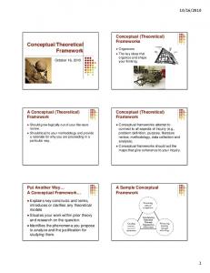
Figure 2: Example of a typical 3D car mesh used for building our model (left) and the polyline network built from it (right). The thick lines are representing the form lines. The thin lines are connection lines that help to maintain the relationships between the various parts. Tovey et al. studied the different levels of sketching [MTN03], and found that so-called form-lines convey the most information about automotive shapes, and usually get drawn first by designers. Our template representation tries to mimic these form lines, and creates a 3D polyline network to represent them. To bootstrap the registration process, we manually extracted these lines from a small set of examples. Figure 2 shows our set of form lines extracted from an example car mesh. Note that our template describes only half a car which is later mirrored to achieve symmetry constraints common in automotive design. Our example data, which we use to build the space of deformations, consists of a set of polyline networks L1 , ..., Lk , where k is the number of examples. The polyline networks are defined manually with the guidance of 3D meshes of real automotive shapes. A specific example is represented as L = hv, n, T i
(1)
where v and n are the vertices and normals extracted from the 3D meshes and T defines the topology of the line network, i.e. T = {(i, j) : vi and v j are connected}.
3.1. The representation for the examples To build our model we start with a dataset which consists of three dimensional mesh representations of automotive shapes (see figure 2 for an example). The different meshes have to be transformed into a consistent representation. Methods in the literature, that tried to establish correspondence between 3D meshes of automotive shapes automatically, failed to provide a high quality mapping of critical features [Bla00, She98]. The drawback of these surface based methods is that they are trying to find a global c The Eurographics Association 2007.
3.2. The space of deformations A straightforward method to build a space of deformations for the above data would be to use the vertex coordinates in their global frame [ACP03, BV99, PSS01]. However this simple and direct representation does not capture the local shape properties and relationships between the vertices. We choose a representation based on deformation gradients, because they have already been succesfully used to define a feature space of 3D meshes for animation purposes
I. Kókai, J. Finger, R.C. Smith, R. Pawlicki, T. Vetter / Example-Based Conceptual Styling Framework for Automotive Shapes
in [SZGP05], and they provide a simple and elegant framework for building and exploring the design space. We build a parameterized space for deformations as follows. We define a mapping Φ that maps a given line network L onto its feature vector f in the space of deformations: f = Φ(L).
(2)
Using Φ to map all examples Li to fi we define the space of desirable deformations. A member of the space is defined with a parameter w as fw = M(f1 , . . . , fk , w).
(3)
M is a function which combines the examples according to the value of w. It is also necessary to define the inverse mapping to get back a visualizable representation from a given feature vector f L = Φ−1 (f).
(4)
Deformation gradients (see [SP04]) are used to define the mapping Φ. Deformation gradients are the non-translational parts of affine transformations. An affine transformation can be uniquely defined with a pair of four non-coplanar vertices. Let vi and v˜ i , i ∈ 1 . . . 4, be the deformed and reference vertices. Calculating the affine transformation that deforms the reference vertices to the deformed vertices requires solving a system of linear equations. Let Q be a 3 × 3 matrix containing the non-translational part of the affine transformation and let d contain the translational part. Then our linear system is Q˜vi + d = vi ,
i ∈ 1 . . . 4.
(5)
If we subtract the first equation from the others to eliminate d and rewrite the system in matrix form, treating the vectors as ˜ = V, where V = [v2 − v1 , v3 − v1 , v4 − columns, we get QV ˜ is defined similarly. From that we get a closed v1 ] and V form expression for the deformation gradient ˜ −1 . Q = VV
(6)
For a chosen reference line network L˜ and deformed line network L, with the shared topology T , we define f = Φ(L) as the concatenated and flattened version of the deformation gradients calculated per line segments. For every line segment (i, j) ∈ T we define the necessary four non-coplanar vertices as follows. The deformed vertices vi , v j , vi + ni and the reference vertices v˜ i , v˜ j , v˜ i + n˜ i with the additional fourth vertices calculated as described in [SP04] are defining V(i, j) ˜ (i, j) respectively. It follows from equation (6) that the and V deformation gradient Q(i, j) for the deformed line segment is linear in the deformed vertices V(i, j) . Assuming a fixed ˜ −1 is the same for all examples. reference line network, V (i, j)
ˇ x + Gˆ ˆ x − fk. x = arg min kGˇ x
x = arg min kGx + c − fk. x
(9)
The simplest feature space is the linear one, where a member fw of the space can be created from the feature vectors f1 , . . . , fk of the example shapes with k
fw =
∑ wi fi .
(10)
i=1
As noted in [SZGP05] the linear feature space is unsatisfactory where large rotations are present among the members of the space. We assumed that this is not the case for automotive shapes where, because of packaging, aerodynamics, and engineering constraints, most of the parts are placed consistently parallel with the ground. Our assumption is that most transformations between cars are occurring as a combination of scaling and shearing. As a consequence, this linear model works fine, and decomposing the deformation gradient into rotation and scale/shear would cause unnatural transitions between the examples (see [SD92]). Equation (10) describes a general setting for a linear feature space, however, the coefficients of the linear combinations must be restricted by additional conditions to ensure realistic results. Because the linear feature space extrapolates poorly, constraining the coefficients to the convex hull by wi ∈ [0, 1] and ∑ki=1 wi = 1 can provide a solution. To satisfy the second constraint implicitly, we form our linear combinations relative to the average ¯f of the feature vectors k
fw = ¯f + ∑ wi ∆fi ,
(11)
i=1
where ∆fi = fi − ¯f. Notice that the parameter vector w in equation (11) is not equivalent with the parameter vector used in equation (10). We replace the first constraint with a probabilistic measure (see [BV00]) by calculating a Principal Component Analysis (PCA) on the vectors ∆fi , i ∈ 1 . . . k, and adding a regularization term to the optimization x,w
(7)
(8)
ˇ as G and xˇ as x in what folFor simplicity we will refer to G ˆ x for the constraints, so the optimization lows and use c = Gˆ problem can be written as
x, w = arg min kGx − Fw − ¯f + ck + ηkwk,
Thus, we can define a linear operator G so that f = Gx,
where x stacks the coordinates of v, n from L and the additional vertices created above. The inversion of Φ is equivalent to solving the equation (7) for x, or inverting G. Because the deformation gradients are translation independent, to hold the solution unique, we have to constrain at least one vertex. We can formulate the above unconstrained equation as a constrained one, with factoring x into a constrained part ˇ x + Gˆ ˆ x. xˇ and an unconstrained part xˆ , that results in Gx = Gˇ We can now write the following constrained optimization problem:
(12)
where F contains the calculated principal components as a c The Eurographics Association 2007.
I. Kókai, J. Finger, R.C. Smith, R. Pawlicki, T. Vetter / Example-Based Conceptual Styling Framework for Automotive Shapes
matrix and η is a weight for the regularization. The PCA could also be used for dimension reduction discarding the components with small effect (which usually contain only noise picked up during the model creation). Automotive shapes are very diverse, thus creating a space flexible enough to represent that diversity needs a lot of examples. As suggested by Blanz and Vetter [BV99], the expressiveness of the model can be increased by dividing the examples into independent segments, e.g. wheels, grill, lights, bumpers, greenhouse, and body. Because their model is built from feature vectors defined in the global frame, they needed an explicit blending operation to generate the complete shape from the segments. As our feature vectors are local in nature and the segments share vertices, the blending happens implicitly during the optimization. We can achieve the segmentation of the space by defining ∆fi from equation (11) as ∆fi = ∆fi1 + . . . + ∆fil ,
(13)
where l is the number of segments, and ∆fi j is the same as ∆fi for the rows that represent the feature values corresponding to the j-th segment of the shape, and have zeros everywhere else. We calculate our PCA for the j-th segment over the vectors ∆f1 j , . . . , ∆fk j .
situation we add a new term to our optimization defined in equation (12). In this case a vector x0 of constraints is given. The x0 is the result of applying some projective transformation to x and selecting a subset of the result. The matrix P provides the connection between x and x0 : x0 = Px
(14)
We can thus rewrite the optimization problem as x, w = arg min kGx − Fw − ¯f + ck + λkPx − x0 k + ηkwk, x,w
(15) where λ provides a weight to define how accurately we would like to approximate the constraints. 4. Interaction with the model 4.1. Dragging points interactively The optimization defined in equation (15) provides a straightforward way to implement meaningful point constraints in the interactive application. Given the actual projection and model-view matrices one can easily define P. Pulling and dragging points [SP03] have an intuitive effect on the shape as figure 4 demonstrates. The result of a more elaborate editing session can be seen in figure 5. Note that because our space is segmented into independent parts, local modifications are possible, i.e., changing the shape of the grill will have the most effect on the front part of the car. With changing the value of λ in the optimization we can define the trade-off between likeliness of the shape and accuracy of the reconstruction of constraints.The dragging of points of the shape interactively provides a way for rapid sculpting-like exploration of different design possibilities. 4.2. Sketching over the lines
Figure 3: Natural constraints for automotive shapes. Points on the center section of the shape are always coplanar, and the wheels are on the ground.
3.3. Exploring the space of deformations Equation (12) provides a simple and efficient way to constrain the model in 3D. Using the properties of car shapes, we can add some meaningful constraints to the model, which will further restrict the space for realistic cars. For example, the points on the centerline should always stay on the symmetry plane of the shape and the wheels should always stay on the ground. These constraints are illustrated in figure 3. These 3D constraints work best where the coordinate values are known precisely (as it is the case for the middle line or the floor level) and no noise is possible. In more realistic situations, which emerge during interactive styling, or during the conversion of a 2D sketch into 3D, we only know the projected coordinates for the constraints, and small uncertainties of the positions are possible. To deal with that c The Eurographics Association 2007.
While dragging points of the shape provides a natural — almost sculpting like — interaction possibility, it is hard to prescribe the exact shape of a given line with it. To provide a more intuitive way to define the lines, we implemented the possibility to sketch over the current model. The work-flow is demonstrated in figure 6. There are two main difficulties with interpreting this kind of input: first a correspondence should be found between the line drawn and the model, and second the line should be projected into 3D. Kara et al. describe a method to solve the above problem [KDS06]. In their application it is assumed that the user intends to modify the curve in the template closest to the drawn line. This closest points correspondence is calculated in the 2D image plane, and the curve is fitted with the help of snakes (or active contours). The resulting 2D curve is projected back into 3D. This back-projection is an ill-posed problem. To provide a reasonable solution they choose the 3D curve from the infinite number of possibilities which is closest to the original (before the modification) target curve. Using our model with the domain knowledge built-in, we
I. Kókai, J. Finger, R.C. Smith, R. Pawlicki, T. Vetter / Example-Based Conceptual Styling Framework for Automotive Shapes
Figure 4: The effect of dragging points. The green dots are constrained points. The red dot depicts the point dragged.
can improve on the above procedure, by simply choosing the curve which minimizes the equation (15). For that we define the term kPx − x0 k with a setting similar to the one described in Kara et al. The strokes drawn are sampled and the two dimensional coordinates define x0 . To find the corresponding points in x we project those into the image plane and for every point in x0 we search for the closest point in x, using the distance between the stroke and model points we can define λ on a per-point basis as the inverse of the distance. After that we can solve our optimization problem and get a result which approximates closely the strokes with a likely shape. An example can be seen on figure 6. 4.3. Recovering the third dimension from 2D input In our proposed work-flow the designer starts with an initial shape and modifies it interactively until the result is satisfactory. To define the initial shape there are several possibilities. The most straightforward one is simply using the average shape or one of the example shapes.
Figure 5: In a typical editing session, the user starts with the average shape (first picture), modifies it interactively to create a novel shape (second), revises the shape (third), evaluates it from a different viewpoint (fourth), and modifies the local details such as the grill and the lights (fifth).
Another possibility is to recreate a design drawn in 2D in the form of sketches or blueprints. In this section we demonstrate a method to convert a 2D sketch (or multiple sketches) c The Eurographics Association 2007.
I. Kókai, J. Finger, R.C. Smith, R. Pawlicki, T. Vetter / Example-Based Conceptual Styling Framework for Automotive Shapes
Figure 6: Sketching over a specific part of the model (top) creates a new shape (middle) which looks reasonable from other viewpoints too (bottom).
into a 3D line model. In the following we will assume that the perspective is known for the input sketches (This is trivial for blueprints, and for perspective sketches one could use a camera calibration technique similar to Kara et al., or ask the user to draw a checkerboard pattern to the ground). To recreate the 2D drawing in 3D the user manually marks some corresponding points between the drawing and the 3D model. The system optimizes the point positions for the markers. An iterative closest point method (based on the closest points defined above) can be used to optimize the rest of the shape. An example is provided in figure 7 .
Figure 7: Using a sketch (first picture). Marked points on the sketch (second) provide the necessary constraints to create the 3D shape (third and fourth).
5. Conclusion In this work we present a novel framework for conceptual styling of automotive shapes. The main novelty of the proposed method is that it leverages existing domain information for interpreting the two dimensional input from the user in a plausible way. Our representation is based on deformation gradients which we extended to handle polyline networks. We present a number of ways to interact with the c The Eurographics Association 2007.
model, including pulling and dragging points in the projected 2D view, editing the current lines by sketching over them. Converting a 2D sketch with known perspective to an initial 3D line model is possible with manual marker placement.
I. Kókai, J. Finger, R.C. Smith, R. Pawlicki, T. Vetter / Example-Based Conceptual Styling Framework for Automotive Shapes
References [ACP03] A LLEN B., C URLESS B., P OPOVIC Z.: The space of human body shapes: Reconstruction and parameterization from range scans. In Siggraph 2003, Computer Graphics Proceedings (2003). [Bla00] B LANZ V.: Automatische Rekonstruktion der dreidimensionalen Form von Gesichtern aus einem Einzelbild. PhD thesis, Eberhard-Karls-Universität zu Tübingen, 2000. [BLMR03] B RUNO F., L UCHI M. L., M UZZUPAPPA M., R IZZUTI S.: The over-sketching technique for free-hand shape modelling in virtual reality. In Virtual Concept (November 2003). [BV99] B LANZ V., V ETTER T.: A morphable model for the synthesis of 3d faces. In SIGGRAPH (1999). [BV00] B LANZ V., V ETTER T.: Reconstructing the Complete 3D Shape of Faces from Partial Information. Tech. Rep. Computer Graphics Technical Report No. 1, Computer Graphics Group, University of Freiburg, 2000. [FdAMS02] F IORENTINO M., DE A MICIS R., M ONNO G., S TORK A.: Spacedesign: A mixed reality workspace for aesthetic industrial design. In ISMAR (2002), IEEE Computer Society, p. 318. [GBK∗ 02] G ROSSMAN T., BALAKRISHNAN R., K URTENBACH G., F ITZMAURICE G., K HAN A., B UXTON B.: Creating principal 3D curves with digital tape drawing. In Proceedings of ACM CHI 2002 Conference on Human Factors in Computing Systems (2002), Two-Handed Interaction, pp. 121–128. [IMT99] I GARASHI T., M ATSUOKA S., TANAKA H.: Teddy: A sketching interface for 3D freeform design. In SIGGRAPH 99, Computer Graphics Proceedings (Los Angeles, August 1999), Addison Wesley Longman, pp. 409–416. [KDS06] K ARA L. B., D’E RAMO C. M., S HIMADA K.: Pen-based styling design of 3d geometry using concept sketches and template models. In SPM 2006 (2006), pp. 149–160. [KH06] K ARPENKO O. A., H UGHES J. F.: Smoothsketch: 3d free-form shapes from complex sketches. [KHR02] K ARPENKO O., H UGHES J. F., R ASKAR R.: Free-form sketching with variational implicit surfaces. Eurographics, Computer Graphics Forum 21, 3 (2002), 585–594. [KS07] K ARA L. B., S HIMADA K.: Sketch-based 3dshape creation for industrial styling design. IEEE Computer Graphics and Applications (January/February 2007), 60–71. [MSK02] M ITANI J., S UZUKI H., K IMURA F.: 3D sketch: sketch-based model reconstruction and rendering. Kluwer Academic Publishers, Norwell, MA, USA, 2002, pp. 85–98.
[MTN03] M. T OVEY S. P., N EWMAN R.: Sketching, concept development and automotive design. Design Studies 24, 2 (March 2003), 135–153. [PSS01] P RAUN E., S WELDENS W., S CHRÖDER P.: Consistent mesh parameterizations. In SIGGRAPH (2001), Fiume E., (Ed.), pp. 179–184. [SD92] S HOEMAKE K., D UFF T.: Matrix animation and polar decomposition. In Proceedings of the conference on Graphics interface ’92 (San Francisco, CA, USA, 1992), Morgan Kaufmann Publishers Inc., pp. 258–264. [She98] S HELTON C. R.: Three-Dimensional Correspondence. Tech. Rep. A.I. Technical Report No. 1650, Massachusetts Institute of Technology Artificial Intelligence Laboratory, December 1998. [Sin06] S INGH K.: Industrial motivation for interactive shape modeling: a case study in conceptual automotive design. In SIGGRAPH 2006 Tutorial Notes "Interactive Shape Modeling" (2006), Alexa M., (Ed.), pp. 3–9. [SMSM06] S EKINE Y., M AEJIMA A., S UGISAKI E., M ORISHIMA S.: Car designing tool using multivariate analysis. In Research posters , ACM SIGGRAPH 2006 Full Conference DVD-ROM Disc 2 (2006). [SP03] S MITH R. C., PAWLICKI R.: Conceptual shape design using optimal estimation techniques. GM R&D Collaborative Report, October 2003. [SP04] S UMNER R. W., P OPOVIC J.: Deformation transfer for triangle meshes. In SIGGRAPH 2004 (2004). [SZGP05] S UMNER R. W., Z WICKER M., G OTSMAN C., P OPOVIC J.: Mesh-based inverse kinematics. In SIGGRAPH 2005 (2005). [TBSR04] T SANG S., BALAKRISHNAN R., S INGH K., R ANJAN A.: A suggestive interface for image guided 3d sketching. In CHI ’04: Proceedings of the SIGCHI conference on Human factors in computing systems (New York, NY, USA, 2004), ACM Press, pp. 591–598. [TKN∗ 03] TANO S., KODERA T., NAKASHIMA T., K AWANO I., NAKANISHI K., H AMAGISHI G., I NOUE M., WATANABE A., O KAMOTO T., K AWAGOE K., K ANEKO K., H OTTA T., TATSUOKA M.: Godzilla: Seamless 2d and 3d sketch environment for reflective and creative design work. In Human-Computer Interaction – INTERACT’03 (2003), et al. M. R., (Ed.), IOS Press, pp. 311–318. [TO00] T OVEY M., OWEN J.: Sketching and direct cad modelling in automotive design. Design Studies 21, 6 (November 2000), 569–588. [YSvdP05] YANG C., S HARON D., VAN DE PANNE M.: Sketch-based modeling of parameterized objects. In International Conference on Computer Graphics and Interactive Techniques (2005), ACM Press New York, NY, USA.
c The Eurographics Association 2007.