Jun 19, 2012 - arXiv:1206.4338v1 [cond-mat.mes-hall] 19 Jun 2012. Excess noise in scanning tunneling microscope-style break junctions at room ...
Excess noise in scanning tunneling microscope-style break junctions at room temperature
arXiv:1206.4338v1 [cond-mat.mes-hall] 19 Jun 2012
Ruoyu Chen1 , Patrick J. Wheeler1 , D. Natelson1,2 1
Department of Physics and Astronomy,
Rice University, 6100 Main St., Houston, TX 77005 and 2
Department of Electrical and Computer Engineering, Rice University, 6100 Main St,.Houston, TX 77005 (Dated: June 21, 2012)
Abstract Current noise in nanoscale systems provides additional information beyond the electronic conductance. We report measurements at room temperature of the nonequilibrium “excess” noise in ensembles of atomic-scale gold junctions repeatedly formed and broken between a tip and a film, as a function of bias conditions. We observe suppression of the noise near conductances associated with conductance quantization in such junctions, as expected from the finite temperature theory of shot noise in the limit of few quantum channels. In higher conductance junctions, the Fano factor of the noise approaches 1/3 the value seen in the low conductance tunneling limit, consistent with theoretical expectations for the approach to the diffusive regime. At conductance values where the shot noise is comparatively suppressed, there is a residual contribution to the noise that scales quadratically with the applied bias, likely due to a flicker noise/conductance fluctuation mechanism. PACS numbers: 71.30.+h,73.50.-h,72.20.Ht
1
Shot noise, first discussed by Schottky in 1918[1], comprises fluctuations in the steadystate, nonequilibrium current that originate from the discreteness of the electron charge. This is “excess” noise in addition to the Johnson-Nyquist[2, 3] current fluctuations that are present at equilibrium in the absence of an applied bias current. Shot noise tends to be suppressed in macroscopic structures at finite temperatures due to electron-phonon interactions. In many mesoscopic systems small compared to the inelastic scattering length for the electrons, shot noise survives and is strongly related to the quantum nature of transport[4]. Many measurements have been performed in this regime on various devices in past two decades, including quantum point contacts[5, 6], diffusive metal conductors[7, 8], break junctions[9, 10], and quantum Hall systems[11, 12]. Most of these experiments are conducted at cryogenic temperatures to avoid thermal smearing of the noise, though shot noise measurements are possible at room temperature in sufficiently nanoscale structures[13]. The classical Schottky shot noise power in the current is SI = 2eI , where SI
is
the spectral density of shot noise, expressed as the mean squared variation in the current h∆I 2 i per unit frequency. Here e is the magnitude of the electron charge, and I is the average DC bias current. This expression is derived assuming the arrival of charge carriers is Poisson distributed, with each electron unaffected by the arrival of a previous electron. Deviations from Poissonian statistics may alter the noise, and these changes are usually expressed in terms of a Fano factor, F , such that the measured noise SI = 2eI × F . Values of F 6= 1 provide clues about the possible effects of interactions and underlying transport processes. The shot noise of mesoscopic conductors at zero temperature is expressed[4] in terms of quantum channels: N X
SI = 2eV G0
i
τi (1 − τi )
(1)
2
where G0 = 2e /h is the quantum of conductance, V is the bias voltage across the junction, and τi is the transmission probability of the ith quantum channel. Combining with the P Landauer formula of G = G0 N i τi , the Fano factor at zero temperature is: F =
PN i
τi (1 − τi ) PN i τi
(2)
The Fano factor carries extra information about the transmission probabilities that a conductance measurement alone cannot provide. At nonzero temperature (though assuming that energy is not exchanged between the charge carriers and other degrees of freedom such 2
as phonons), the situation is more complex, as the thermal Johnson-Nyquist noise and shot noise are not readily separable. The total current noise will be: SI = G0 [4kB T
N X i
N
τi2
eV X ) τi (1 − τi )] + 2eV coth( 2kB T i
(3)
kB is the Boltzmann constant. In the equilibrium limit V = 0, both terms in this formula will survive and contribute to Johnson-Nyquist thermal noise of 4kB T G. In the zero temperature limit, the total noise power will reduce to Eq. (1). Temperature manifests itself through the smearing of the Fermi-Dirac distribution of the electrons. From these equations it is clear that fully transmitting channels (τi → 1) do not contribute to the shot noise. This leads to a relative suppression of the noise in nanoscale systems when the conductance is largely from such open channels, as in semiconductor point contacts exhibiting quantized conductance[5], and in metal point contacts[9]. In the few channel limit, the conductance combined with the noise allow the determination of the number of channels and their transmission probabilities[10]. In the many-channel limit of diffusive conductors, random matrix theory has provided valuable insights, and the Fano factor is expected to √ approach an average value between 1/3 and 3/4[14–17] depending on bias conditions and sample geometry. These predictions have been confirmed in the low temperature limit[7, 8, 18, 19]. Inelastic processes such as the excitation of local vibrational modes are predicted to alter F as the bias voltage exceeds the energy scale of such excitations[20–22]. Such effects have been observed at low temperatures in nanotubes[23], bilayer graphene[24], and very recently in atomic-scale Au junctions[25], though the particular changes in F depend in detail on channel transmission. One motivation of this work is the need to perform experimental comparisons with Eq. (3) in a temperature regime where inelastic processes are favored by kB T exceeding the characteristic energy scale for other degrees of freedom. For example, at 300 K, the lowest optical phonon mode in Au (∼ 17 meV[25]) should already be populated. In this paper, we consider the noise properties of ensembles of atomic-scale metal point contacts from tunneling to the multichannel (G ∼ 6G0 ) regime, at room temperature, when inelastic processes involving phonons should be considerably more important than in the cryogenic limit. Of particular interest are the accuracy and utility of Eq. (3) under these conditions, over a broad range of applied bias, and the relative contributions of other noise mechanisms, such as conductance fluctuations[26]. With biases ranging from 1 < eV /kB T < 10, 3
we find noise consistent with Eq. (3), with clear relative suppression of the noise at conductance values corresponding to the quantized conductance peaks in the ensemble histograms. At still lower bias, we cannot resolve the excess noise, while conductance peaks remain still clear. The Fano factor in the high conductance, high bias regime is approximately a third of that in the G < G0 tunneling regime. At the conductances where noise is relatively suppressed, the bias scaling of the averaged noise is consistent with conductance fluctuations, and the magnitude is not unreasonable considering previous experiments[27]. ���� ���
�� ��
���� ���
� �� �� �����
0���� 32������ 1���� 4��� ��� ��2 �� :��������� ����8� 8 $%&' ( % ��9 .-/
������ 5��67�� � �� �� �!�"# ��� $%&'
( %
5��67�� ������ � �� �� ��� �!�"#
)*##"�+ ,#"� �2
��� � �7 � �� �� �!�"# -��
���87 ���� 3���� �
���� ���� ������� �������
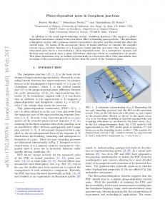
FIG. 1. The schematic of the circuit used to measure DC conductance and RF noise power. All the RF components in this circuit have 50 Ω impedance except the sample.
These experiments are performed using a scanning tunneling microscope (STM)-style break junction, as has become very popular in the study of molecular conduction[28, 29]. A junction is repeatedly made and broken in ambient conditions between a 50 nm-thick gold film evaporated on an oxidized silicon substrate, and a cut gold wire. A computercontrolled piezo actuator is used to form and break the junction typically several times per second. The noise measurement approach is similar that employed previously in a flexural mechanical break junction[13]. The desire to examine the ensemble-averaged noise leads to the choice of the STM break junction method; the need for rapid measurement of the noise during the junction breaking process necessitates the use of a high bandwidth radio frequency (RF) technique. Throughout the junction formation and breaking cycle, a “DC” bias square wave (between 0 V and a desired voltage level, with a frequency of approximately 10 kHz) is applied across the series combination of the gold junction and a current-limiting 2 KΩ resistance standard. This low frequency square wave serves as the (essentially) DC bias that drives current through the junction. The circuit, as shown in Fig. 1, employs bias-tees to separate the DC and RF signals coming from the junction. A 4
current preamplifier measures the current and is recorded electronically, giving a measure of the junction’s conductance. At the same time, a lock-in amplifier synchronized to the square wave detects the difference between the RF power with and without bias applied to the junction; this is the excess noise power. The bandwidth of the noise measurement is roughly 250-580 MHz. A detailed gain-bandwidth product measurement is employed. Since both shot noise and Johnson-Nyquist noise are expected to be white over this bandwidth, deviations from white noise arise from the impedance properties of the measurement circuit as a whole. The details of the noise analysis and background subtraction are described in supplemental material. At every single bias, the STM style motion of the gold tip repeats hundreds times to generate a histogram of conductance, as well as a plot of the ensemble averaged excess noise power vs. conductance. An example is provided in Fig.2. As has been seen in many previ-
FIG. 2. An example of conductance quantization (a) and noise suppression (b) at room temperature. (a) A conductance histogram acquired with 180 mV amplitude for the biasing square wave. (b) Averaged power spectral density vs. conductance. The bin size in both plots is 0.01 G0 .
ous experiments in atomic-scale metal contacts[30], peaks are observed in the conductance histograms, signifying preferred junction configurations with specific values of conductance. Peaks are observed at 1 G0 , and near other integer multiples of G0 , consistent with past results on Au junctions at room temperature[31]. Cryogenic experiments involving shot noise[9] and subgap structure in superconducting contacts[32] have demonstrated that the 1 G0 peak in Au junctions is dominated by configurations with a single highly transmitting channel (τ → 1). In our structures usually the first three conductance peaks are readily 5
resolvable in the histogram. The related ensemble-averaged noise power measurement is also shown. As is clear from the figure, the ensemble-averaged noise power is clearly suppressed near conductance values where the conductance histogram is peaked. The transmission of RF signals always faces the problem of power reflection, which originates from impedance mismatch. Conversely, reflection itself carries information about impedance. In our measurement circuit, all the commercial RF electronic components are of 50Ω impedance. We therefore expect significant impedance mismatch and reflections only between the STM-style gold junction and the transmission lines. As an added complication compared to a fixed device configuration, the tip’s repeatedly vertical motions introduce the extra complexity of a strongly time-varying DC conductance into the junction’s RF properties. In principle a measurement should be performed to properly characterize the impedance mismatch between the junction and the RF measurement circuitry at each conductance value. Ideally, knowing the RF properties of the nanoscale junction and the accompanying electronics, including the gain-bandwidth product of the amplifier chain, it should be possible to infer the actual current noise (A2 /Hz across the junction) from the measured RF power seen by the power meter. However, in the STM breakjunction setup, in which the DC conductance of the junction changes by orders of magnitude on millisecond timescales, with our equipment it is not possible to measure all of the relevant RF parameters in real time. As an approximation to this, we instead measure the reflection properties as a function of conductance averaged over the ensemble of junction configurations. This should at least indicate whether there are gross variations in the efficiency of the junction’s RF coupling to the rest of the circuit. Following on the approach reported previously in measurements of the impedance properties of a vacuum photodiode[13], we perform a reflectance measurement as shown in Fig. 3. A commercial white noise source is used to provide wide-band white noise across the RF bandwidth of interest. The amplitude of this noise is modulated by a subsequent RF switch that is turned on and off at the same (acoustic) frequency used for the square wave voltage bias we applied in excess noise measurement. Part of the white noise will be reflected at the boundary between the gold junction and the transmission line to the bias tee. The reflected power goes through a directional coupler as well as the same amplifier chain used in the excess noise measurements, and is registered by the logarithmic power detector. Simultaneously, the junction’s cyclical STM-style motion is executed, with an applied DC 6
bias across the junction to allow the simultaneous acquisition of a conductance histogram. This measurement gives a picture of the relation between ensemble averaged reflections and the conductance of the junction. While the reflection measurement cannot provide all the information about the junction’s RF properties, at least it provides a rough check that nothing dramatic happens in terms of the ensemble-averaged impedance mismatch over the conductance range. The reflection averaged over the ensemble of junction configurations is around 22%. There is some systematic variation with conductance, but this is small, less than 2% over 10 G0 . Since the impedance mismatch between the junction and the measurement circuit does not vary dramatically on average over the range of junction configurations, there should be a scale factor (approximately constant across the conductance range) between the measured power and the true current noise across the junction. We attempt to find this factor by using the knowledge that the Fano factor in the tunneling regime G