Originally, our work was motivated by the approach of Shimizu, Dill and Hu [23]. ...... We are grateful to David Dill and Kanna Shimizu for discussions and ...
Executable Protocol Specification in ESL? E. Clarke1 1
S. German2
Carnegie Mellon University
2
Y. Lu1
H. Veith1;3
IBM T. J. Watson Research Center
D. Wang1 3
TU Vienna
Abstract. Hardware specifications in English are frequently ambiguous and often self-contradictory. We propose a new logic ESL which facilitates formal specification of hardware protocols. Our logic is closely related to LTL but can express all regular safety properties. We have developed a protocol synthesis methodology which generates Mealy machines from ESL specifications. The Mealy machines can be automatically translated into executable code either in Verilog or SMV. Our methodology exploits the observation that protocols are naturally composed of many semantically distinct components. This structure is reflected in the syntax of ESL specifications. We use a modified LTL tableau construction to build a Mealy machine for each component. The Mealy machines are connected together in a Verilog or SMV framework. In many cases this makes it possible to circumvent the state explosion problem during code generation and to identify conflicts between components during simulation or model checking. We have implemented a tool based on the logic and used it to specify and verify a significant part of the PCI bus protocol.
1 Introduction Motivation. The verification of bus protocols, i.e., of communication protocols between hardware devices, as in the case of the well-known PCI bus, is a central problem in hardware verification. Although bus protocol design and verification have become increasingly important due to the integration of diverse components in IP Core-based designs, even standard bus protocols are usually described in English which makes specifications often ambiguous, contradictory, and certainly non-executable. Example 1. It is often the case that English documentation attaches different meanings to a single name in different situations, as in the following definition for “data phase completion” from PCI 2.2 [19], page 10: A data phase is completed on any clock both IRDY# and TRDY# are asserted. On Page 27, however, there is a different definition: A data phase completes when IRDY# and [TRDY# or STOP#] are asserted. The obvious problem with these definitions is whether data phase completion should include the case when both IRDY# and STOP# are asserted. By carefully reading the English documentation, one can also find many contradictory statements, as in the following example from PCI 2.2 [19], page 50: Once the master has detected the missing DEVSEL#, FRAME# is deasserted and IRDY# is deasserted. On Page 51, however,
? This research is sponsored by the Gigascale Research Center (GSRC), the National Science Foundation (NSF) under Grant No. CCR-9505472, and the Max Kade Foundation. One of the authors is also supported by Austrian Science Fund Project N Z29-INF. Any opinions, findings and conclusions or recommendations expressed in this material are those of the authors and do not necessarily reflect the views of GSRC, NSF, or the United States Government.
it is said that Once a master has asserted IRDY#, it can not change IRDY# or FRAME# until the current data phase completes. The reason why these two are contradictory is that the first sentence allows FRAME# to be deasserted without the current data phase being complete, while the second one disallows this.
Traditional hardware description languages are usually not well-suited for protocol specification because they are based on existing concrete designs (or abstractions thereof) instead of specifications, and their execution model therefore focuses on single-cycle transitions. With protocols, the specification is naturally represented by constraints on signals which may connect relatively distant time points. Another problem of transition-system based approaches is that naive composition of participants in the protocol may cover up important protocol inconsistencies due to synchronization faults or write conflicts among non-cooperative participants. It is important that the specification language be executable, i.e., that a machine model can be computed from the specification. This is a trivial property for hardware description languages, but not for protocol specifications.
Protocol Specification
Verilog Program
Verilog Simulation
Protocol Module Module e.g. Master
Master Module Module e.g. Slave
Slave Module Module Module
Additional Functionalities:
Generation of SMV Module
CombinerMachine Tableau
Script
Mealy Machine
Construction
Script
Verilog Module
SMV Model Checking
Synthesis Submodule
Submodule
Submodule
Mealy Machine
Script
Consistency Checking
Mealy Machine
Fig. 1. System Overview
The ESL logic. We propose the new logical language ESL which facilitates specification, verification, and simulation of protocols. ESL is based on a variant of linear temporal logic (LTL) where atomic propositions are constraints on signals in the protocol, e.g. REQ 2 f ; g. The core of ESL are ESL scripts, i.e., finite collections of executable temporal formulas. More precisely, a script is a finite collection of axioms �P ) �X where �P is a temporal formula involving only the temporal operator (immediate past-time), and �X is a temporal formula involving only the temporal operator , e.g. a ) b _ a. Atoms in �P are interpreted as tests of previous signals, while �X asserts constraints in the future. Scripts may contain local variables which are not visible in the traces (i.e., models) of the script. An ESL module E is a finite collection S1k : : : kSn of ESL scripts. The intended semantics is that ESL scripts describe Mealy Machines and that the ESL module specifies
02
P
X
P
XX
the synchronous composition of the Mealy machines. Different scripts of a module potentially conflict if they employ common output signals. Note that in general two scripts S1kS2 describe two different Mealy machines, while the conjunction S1 ^ S2 of two scripts is itself a script which describes a single Mealy machine. A finite collection P of ESL modules with pairwise disjoint output signals is called an ESL protocol. The semantics of an ESL protocol is the synchronous composition of its modules. ESL modules cannot directly conflict with each other, but they may have receptiveness failures (see Section 5). In real protocols, ESL scripts describe distinct functionalities and features of hardware devices, while ESL modules correspond to the devices themselves. Note that different scripts can constrain the same signal, which is important when translating natural language specifications. Experiments and Results. We show that semantically ESL expresses exactly the regular safety properties. This property is crucial for synthesizing executable models of the protocol, and distinguishes it from other executable logics, e.g. [12]. A fragment of L USTRE has been shown to capture the same expressive power [14] in the context of synchronous data-flow languages for real-time systems. We present efficient tableau and synthesis algorithms to obtain executable models of hardware protocols, cf. Figure 1. The tricky aspect of synthesizing hardware protocols is to group the signals occuring in the specification into output signals and input signals. To this aim, we introduce a marked tableau construction which preserves the distinction between past observations and future assertions. Since each script is converted into a Mealy machine separately, there is no state explosion during the translation phase. The execution of ESL in Verilog and SMV makes it possible to use the power of well-known and highly developed verification paradigms; in particular, it is possible to verify important features about the ESL protocol, such as synchronization contradictions between different scripts and receptiveness [2] of the ESL modules. Another important debugging method is property checking, i.e., existing Verilog monitors and model checking tools can be easily used to debug ESL protocols. To improve coverage of the Verilog simulation, a dynamically biased random simulation test bench [20] can also be written directly in ESL scripts. In a case study, we have used ESL to specify the PCI bus protocol Rev 2.2 [19]. Several errors were identified, including some errors from t he English specification. Verilog monitors and temporal formulas from [23] have been checked against the generated Verilog and SMV models. Related Work. Algorithms for synthesizing concurrent and distributed programs from temporal logic specifications have been developed for CTL by Clarke and Emerson [7, 8] and for LTL by Manna and Wolper [16]. Both methods synthesize global state transition systems based on an interleaved asynchronous model of computation and then use projection to obtain controllers for individual processes. Neither of these methods has been very successful because of the computational complexity of the decision procedures involved. Protocol synthesis, especially synthesis of bus protocols, is easier, since many implementation details are already given. Our methodology automatically exploits this information by incorporating it into the synthesis process.
Various formalisms have been used in hardware specification and synthesis [11, 15, 18, 21]. Recently, Shen and Arvind used term rewriting systems to specify and verify ISA and out-of-order implementations of processors [22]. Gabbay has developed an executable logic [12] for AI applications in which programs are written using rules of the form “If A holds in the past then do B”. Since liveness properties can be expressed in his logic, it is not suitable for Verilog simulation. Originally, our work was motivated by the approach of Shimizu, Dill and Hu [23]. They use monitors to specify bus protocols formally, based on rules of the form ”predicate on past states ) predicate on current state”. A coding style is defined that promotes readability, discourages errors, and guarantees receptiveness. We use a similar definition of receptiveness (see Section 5). Although our paper is also concerned with formal specification of bus protocols, there are several important distinctions between the two papers. First, our formalization is a declarative formalism based on temporal logic. Second, their monitors are restricted to interface signals. Consequently, constructing appropriate monitors can be tricky. For example, identification of “master abort” in the PCI bus protocol involves observing the bus for several cycles. Third, both Verilog and SMV models can be obtained from our specifications. Our Verilog model can directly generate valid simulation patterns and can, therefore, be simulated with part of the real design. In the monitor approach, the Verilog versions of the monitors are only applicable to a complete design, because monitors can not be used to generate valid patterns. Consistency problems arise at different levels of specifications. Bryant et al [4] have developed a notion of consistency by identifying combinational dependencies. They show how to derive the consistency model from a modular specification where individual modules are specified as Kripke structures and give an algorithm to check the system for consistency. Very recently, the system FoCs has been developed at IBM Haifa [1]. FoCs automatically generates simulation checkers from RCTL specifications. A more detailed exposition of the related work and proofs will be given in the full version of this paper. Structure of the Paper In Section 2, we describe the logical framework of ESL. Section 3 contains the protocol description language which is used as input to our tool. In Section 4, the translation algorithms are presented. Section 5 shows how to debug and verify protocols. Finally, Section 6 contains our practical experiments with the PCI bus protocol. In Section 7, we briefly summarize our work, and outline future work.
2 The ESL logic In this section we describe the linear time logic which underlies the implementation of the ESL system. A more user-friendly input language for ESL will be described in the following section. 2.1 Temporal Logic on Signal Traces
V = fv1 ; : : :; vng be a set of variables (signals) where each vi has finite domain Dvi . A variable vi is Boolean, if its domain Dvi is f0; 1g. An atom is an expression
Let
vi = d, where d 2 Dvi . The finite set of atoms is denoted by Atoms. If vi is Boolean, then vi abbreviates vi = 1. Literals are atoms and negated atoms. For a set A of atoms, var(A) = fv : for some value d 2 DVi ; v = d 2 Ag is the set of variables appearing in A. A type is a consistent conjunction 1�i�n �i of literals. As is common in logic, we shall often write types as sets f�1; : : :; �ng. A complete type is a type which determines
the values of all variables. Note that each complete type can be assumed to contain only (unnegated) atoms. Example 2. Suppose that V = fREQ; COMg, where DREQ = f1; 2; 3g, and DCOM = f0; 1g. Then fREQ = 1; REQ = 2; REQ = 3; COM = 0; COM = 1g. Examples of two types �1 ; �2
Atoms = are: 1. 2.
�1 = �2 =
REQ = 1; COM 6= 0g, or as a conjunction, �1 becomes REQ = 1 ^ COM 6= 0. REQ 6= 2; COM = 1g, or as a conjunction REQ 6= 2 ^ COM = 1.
f f
�1 is a complete type, because it determines the values of both REQ and COM. �1 is equivalent to the type fREQ = 1; COM = 1g. �2 does not determine the value of REQ, because both REQ = 1 and REQ = 3 are consistent with �2 . Therefore, �2 is not complete. ESL is based on a discrete time model, where time points are given by natural f ; ; : : : g. A signal trace is an infinite sequence S s1 s2 � � � , numbers from N where each si determines the values of all variables at time i. S can be viewed as an infinite string, where the alphabet consists of complete types. Following the previous example,
= 12
=
S = fREQ = 1; COM = 0gfREQ = 1; COM = 1gfREQ = 3; COM = 1g : : : is a signal trace. Thus, the alphabet of signal traces is given by
� = f� 2 2Atoms : � is a complete type without negationg: The set of signal traces is given by � ! . Traces which do not determine the values of all signals are important for us as well (see Section 4.1). For this purpose, we use the alphabet � which consists of all types, i.e., partial assignments to the signals. Note that � is a superset of the signal trace alphabet � . Formally, we define
� = f# : # is a typeg: The set of traces is given by �! . Remark. To keep the presentation simple, we tacitly identify two elements of �, if they are logically equivalent, e.g., COM and COM 6 . Thus, a rigid formal definition of � would require that the alphabet � is given by the finite number of equivalence classes of types. For example, we may use the lexicographically minimal types as representatives of their equivalence classes.
=1
=0
Since � � �, every signal trace is a trace, and all definitions about traces in principle also apply to signal traces. The main difference between � and � is that each
element of � determines the values of all signals, while � may contain partial information. On the other hand, with each element # of � we can associate all elements of � which are consistent with #. To this end, we define the function comp � ! � by
:
2
comp(#) = f� 2 � : � ) #g: comp is called the completion function, because it maps a type # to the set of all complete types consistent with #. In other words, comp maps a partial assignment to the set of possible complete assignments. Let T t1 t2 � � � 2 �! be a trace. Then the set of signal traces described by T is given by
=
comp(T ) = fS = s1 s2 � � � 2 � ! : for all i, si 2 comp(ti )g:
( ) = fcomp(T ) : T 2 Lg. Given two sets L1; L2 of traces, (L1) = comp(L2 ), i.e., L1 and L2 describe the same set
For a set L of traces comp L we define L1 � L2 iff comp of signal traces.
Example 3. Let REQ and COM be as in Example 2. Then the trace ! does not determine 1; REQ = 1gfCOM = 0; REQ 6= 2g)
T = REQ
(fCOM
=
in all positions. It is easy to see that comp(T ) is given by the !-regular expression ! (fCOM = 1; REQ = 1gfCOM = 0; REQ = 1gjfCOM = 1; REQ = 1gfCOM = 0; REQ = 3g)) :
A trace property L is a set of signal traces. Ln denotes the set of finite prefixes of length n of words in L. A safety property is a trace property L, such that for each t 62 L, there exists a finite prefix r of t, such that r 62 Ljrj . In other words, traces not in L are recognized by finite prefixes. For a set S of atoms and a set X � V of variables, let SX denote the restriction of S to atoms containing variables from X only. Similarly, �X denotes the alphabet of complete types for the set of variables X . V is partitioned into two sets VG and VL of global and local variables. The distinction between global and local variables will be justified in Section 2.2. Thus, SVG denotes the restriction of S to global atoms, i.e., atoms using global variables. Similarly, �VG denotes the alphabet of complete types for the set of variables VG . Let be the projection function which maps � to �VG by
global
global(�) = � \ AtomsVG : Intuitively, the function global removes all local atoms from the alphabet. With each signal trace S = s1 s2 � � � we associate the global signal trace global(S ) = global(s1)global(s2 ) � � � over 2AtomsVG . Example 4. Let S
R = 1; a = 2 R = 0; a = 3 variable. Then global(S ) = ( R = 1 R = 0 )! . = (f
g)
gf
f
gf
! be a signal trace where a is a local
g
Given two sets L1 ; L2 of traces, we define L1 �gl L2 iff global(comp(L1 )) = global(comp(L2)), i.e., L1 and L2 describe the same set of global signal traces. Lemma 1. If L is a safety property, then global(L) is a safety property.
X P
=
G
We consider a linear time logic with temporal operators , , and . Let T be a trace. We inductively define the semantics for atomic formulas f and temporal operators , , as follows: T; i j f iff ti ) f (Here, we use the fact that ti is a type, and thus a formula.) T; i j ' iff T; i j ' T; i j ' iff i � , and T; i ? j ' T; i j ' iff 8j � i T; j j ' The semantics of the Boolean operators is defined as usual. Existential quantification over traces is defined as follows: Let v be a variable, and let T t1 t2 � � � be a trace over �V ?fvg, i.e., a trace which does not assign values to v. Then we define T; i j 9v:' iff there exists an infinite sequence a1 a2 : : : of values for v such that the trace S t1 [ fv a1 g t2 [ fv a2 g : : : satisfies ' at time i, i.e., S; i j '. Given a formula ', ' denotes the set of signal traces T such that T; j '. Traces can be combined in a very natural manner:
t1 t2 : : :
= =X =P =G
X P G +1 = 2
=
1=
=
=
=(
= )( Traces( )
=
=
=
)
= 1=
t1 t2 � � � and S s1 s2 � � � be traces. Then the combined trace Definition 1. Let T T 1 S is given by the infinite sequence u1u2 � � � where
(
ui = ti ^ si
if ti and si are consistent
ffalseg otherwise
= false
We say that T and S are compatible if there is no i such that ui f g. Otherwise we say that T and S contradict. Let L1 and L2 be sets of traces. Then L1 1 L2 fT1 1 T2 T1 2 L1 ; T2 2 L2 g.
=
:
The above definitions easily generalize to more than two traces. Note that the operation 1 introduces the new symbol in the alphabet of traces. The following important example demonstrates why the operator 1 is different from conjunction, and why we need it to analyze traces.
false
Example 5. Consider the two formulas of traces are given by
G (a ) X b) and G (a ) X :b). Their sets
Traces(G (a ) X b)) � (fagfbgjf:ag)! and
Traces(G (a ) X :b)) � (fagf:bgjf:ag)!:
When viewed as specifications of different devices, the two formulas are intuitively contradictory when the input signal a becomes true. In fact, in the set of combined traces
Traces(G (a ) X b)) 1 Traces(G (a ) X :b)) � (fagffalsegjf:ag)! the contradictions become visible immediately after a becomes true. On the other hand, the naive conjunction a ) b ^ a ) :b of the formulas is equivalent to :a, their set of traces is given by :a f:a; bgjf:a; :bg !, and thus the potential contradiction vanishes.
G
G(
X ) G( X ) Traces(G ) = (
)
2.2 ESL scripts The following definition describes the fragment of linear time logic used in ESL. Definition 2. ESL scripts (i) A retrospective formula is a formula which contains no temporal operators except P . (ii) A prospective formula is a formula which contains no temporal operators except . (iii) A script axiom � is a formula of the form �P ) �X where �P is a retrospective formula, and �X is a prospective formula. V (iv) An ESL script S is a conjunction 1�j �k �j of script axioms V �j . � . (v) With each script S , we associate the formula S 1�j �k j
X
G( )=G
Intuitively, atoms in �P are interpreted as tests of previous signals, while �X asserts constraints in the future. For simplicity, we assume that no local variable appears in two different ESL scripts. Example 6. Consider the ESL script P a ^ a ) (X a _ X X a). The script says that if a held true in two subsequent cycles, then a must hold true in one of the two following cycles.
The following lemma says that the temporal operator
G( )
P
is redundant.
Lemma 2. Let S be an ESL script. Then S is equivalent to a formula of the form 'G ^ 'Init , where 'G and 'Init are temporal logic formulas which contain no temporal operators except .
G( )
X
The following theorem states that the projection operator effect as existential quantification.
S be an ESL script, and l1 ; : : :; ln global(Traces(G S )) = Traces(9l1 � � � ln G(S )).
Proposition 1. Let
global achieves the same its local variables. Then
Thus, projection amounts to a kind of implicit existential quantification. The effect of this quantification is characterized by the following theorem. Theorem 1. On global signals, ESL scripts capture the regular safety properties. Formally, for each regular safety property L over �VG , there exists an ESL script S such that S L, and vice versa.
global(Traces(G( ))) =
We conclude from Theorem 1 that projection extends the expressive power of the logic to capture all regular safety properties on global variables. We will show in the next section that in praxis the complexity of our logic does not increase significantly. Thus, the addition of local variables appears to be a good choice which balances expressive power and complexity. Corollary 1. For global variables, all past time temporal operators, as well as the weak until operator W are expressible by ESL scripts.
2.3 Regular tableaus The tableau of an LTL formula ' is a labeled generalized B¨uchi automaton T that accepts exactly the sequences over Atoms' ! that satisfy ' [13]. (Here, ' denotes the set of atomic propositions appearing in '.) In this section, we define regular tableaus by adapting LTL tableaus to ESL.
(2
)
Atoms
Definition 3. Regular Tableau A regular tableau T is a tuple hS T ; S0T ; AT ; LT ; R T i where
is a finite set of states, S0T � S T is a set of initial states, and AT is a finite set of atoms. – LT S T ! � is a labeling function which labels states by types, where � is the set of types over AT . – R T � S T � S T is the transition relation of the tableau.
–
ST
:
Since by Theorem 1, ESL defines only safety properties, tableaus for ESL do not need all the expressive power of !-automata. Moreover, the states of regular tableaus are labeled only by sets of atoms (and not by temporal formulas). Intuitively, temporal formulas can be omitted from tableaus because we have local variables which carry the information that is usually carried by the temporal formulas. Definition 4. Regular Tableau Acceptance A trace T t1 t2 � � � 2 �! is accepted by T if there exists a sequence s1 s2 � � � 2 such that
=
(ST )!
(i) s1 2 S0T (ii) s1 s2 � � � is an infinite path in the graph given by the transition relation RT . (iii) For all i, ti ) LT si .
( )
( )
The language L T is the set of traces T accepted by tableau T . Let S be an ESL script, and T a tableau. T is a correct tableau for S , if L T � S ; i.e., if the traces generated by the tableau define exactly the signal traces which satisfy S .
( ) Traces(G( ))
3 ESL Protocols ESL facilitates modular specification of protocols, in particular hardware protocols. ESL protocols consist of modules which in turn consist of scripts. Under the intended semantics of ESL, modules correspond to distinct devices (e.g. a master and a slave device), while scripts describe independent functionalities of the devices. Formally, an ESL module E is a finite collection S1; : : :; Sn of scripts. Each script Si is given by a finite conjunction V 'j of specifications. The intended semantics is that ESL scripts describe Mealy Machines and that the ESL module specifies the synchronous composition of the Mealy machines. Therefore, we shall write S1 kS2 : : : kSn to denote E . Different scripts for the same module potentially conflict if they employ common output signals, i.e., common global variables which model output signals. Scripts may contain local variables which are not visible to other scripts.
Our aim is to build a machine ME such that the language accepted by ME coincides with the combined traces of the scripts on global variables, i.e.,
L(ME ) �gl Traces(S1) 1 � � � 1 Traces(Sn ): As shown in Example 5, trace combination will enable us to identify contradictions between scripts. A finite collection P of ESL modules with pairwise disjoint output signals is called an ESL protocol. The semantics of protocols is given by the semantics of the scripts of its constituent modules. ESL modules of a protocol have fewer sources of conflict among each other than ESL scripts because they do not have common output signals. 3.1 Input Language for ESL Protocols An ESL protocol must contain exactly one protocol module which starts with the keyword protocol. Each module can have three types of variables: input, output and local variables. Each script can include more than one specification, which start with the keyword spec. To facilitate easy description of properties and protocols, we augment the basic ESL language with syntactic sugar, such as default values, additional temporal operators, and parametrized macros. In particular, we use the weak until operator W and the operator keep a which asserts that the current value of signal a is the same as in the previous step. Note that by Lemma 2, we can add all the past temporal operators to the language because they only define regular safety properties. Parameters are used to adapt specifications to hardware configurations of varying size. Due to space restrictions, we describe the input language by example. The following example is a fragment of the specification of the PCI bus in ESL. It consists of one master and one arbiter.
()
module pci master input output local local script script endmodule module pci arbiter parameter input output local script spec
RST
endmodule
clock; GNT: bool; REQ = 0: bool; status : fCOMP; MABORT; MTOg; retry req; last cycle; addr phase: bool; spec retry req ) X (retry req W addr phase); spec last cycle ) :retry req; spec GNT ) X(keep(REQ)) W status = COMP;
N;
RST; REQ[1 to N]: bool; GNT[1 to N]: bool; tok[1 to N]: bool;
^
tok[i] ) X (tok[(i + 1) Mod N] = 1
^
tok[i] = 0)
for i = 1 to N;
protocol pci bus constant modules
N = 2;
master[1 to N]: arbiter(N):
pci master, pci arbiter;
master[i]:GNT arbiter:REQ[i]
=
connection
endprotocol
=
arbiter:GNT[i] for i = 1 to N ; master[i]:REQ[i] for i = 1 to N ;
This example includes two modules and one protocol module. Each module includes one or two scripts. In the module pci master, REQ has Boolean type and is initialized to 0. The local variable status denotes whether the PCI master aborts the transaction or the time out happens. In the module pci arbiter, we define a parameter N which will be instantiated when the module gets instantiated. A formula ' i i N is equivalent to ' ^ ' ^ : : :^ ' N . For example, the script of the module pci arbiter is instantiated as a conjunction of two formulas:
(1) (2)
( )
( ) for = 1 to
(RST ^ token[2] ) X (token[1] := 1 ^ token[2] := 0)) ^ (RST ^ token[1] ) X (token[2] := 1 ^ token[1] := 0)) The protocol module explicitly connects the modules pci master and pci aribter by matching the corresponding inputs and outputs.
4 Synthesis of Executable Models Given an ESL protocol, our procedure comprises three main steps to transform executable models into either Verilog or SMV programs. 1. Preprocessing. In this step, the ESL protocol is parsed and type checked to make sure each variable is declared and each axiom is well typed. For example, for a Boolean variable x, an atom x is not allowed. Furthermore, the parameters are instantiated and the macros are expanded. 2. Module Synthesis. This step converts each ESL module separately into a Verilog or SMV module. An overview of the algorithm ModuleSynthesis given in Figure 2. In the algorithm, we first generate a regular tableau for each script and translate the tableau into a nondeterministic automaton. Then we determinize the automaton and translate it into a Mealy machine which can be easily implemented in Verilog or SMV. The combiner connects each Mealy machine. Details of each step will be described in the following three subsections. 3. Module Connection. In this final step, the inputs and outputs from different ESL modules are connected. In the synchronous bus protocol design, combinational dependency loops between the signals are not allowed. This step identifies all combinational dependencies within individual modules or between modules. A short outline of this step is given in Section 4.4.
=3
Algorithm ModuleSynthesis(S1k � � � kSn ) foreach Si (Si ) TSi = (TSi ) NSi = D NS = ( NSi ) i D (NSi ) MSi = return Combine(MS1 ; : : : ; MSn )
Algorithm MTableau(S ) mark S
MTableau Automaton Powerset GenMealy
TS
:= Tableau(S )
for all states s 2 S TS T if (L S ) is inconsistent then remove s from TS return TS
clean
Fig. 2. Algorithm to synthesize scripts
Fig. 3. Tableau Construction.
4.1 Tableau construction Given an ESL script S , our aim is to generate a Mealy machine whose operational behavior is specified by the script. Consider the two simple scripts a )b and b ) a , where a and b are Boolean variables. Logically, these scripts are equivalent (since a ) b is equivalent to :b ) :a.) However, as specifications for Mealy machines they should intuitively describe different machines: the formula a ) b describes a Mealy machine which asserts b if it observes a , while b ) a describes a Mealy machine which asserts a if it observes b . We conclude from this example that for the operational behavior of the Mealy machines it is important to know for each occurrence of a variable whether it belongs to the retrospective or the prospective part of a script. Variables from the retrospective part eventually will become inputs of Mealy machines, and variables from the prospective part will become outputs of Mealy machines. In our methodology, we first build a tableau for S , and then translate it further to a Mealy machine. As argued above, it is important for our tableau construction not to lose the information which variables will be used as outputs of the Mealy machine later on. Therefore, we distinguish such variables by marking them with a symbol �.
=0
=1
=0
=1 =1 =0 =0 =0
=1
=0
=1
=1
=
fv1; : : :; vng, V � is a set fv1� ; : : :; vn� g of Definition 5. Given a set of variables V new variables called marked variables. Given an ESL axiom ' �P ) �X and the corresponding alphabet �, the marked axiom 'm is given by �P ) ��X where ��X is obtained from �X by replacing each occurrence of a variable v by the marked variable v� . ESL scripts are marked by marking all their axioms. Let X be a set of variables or atoms etc. Then X denotes the subset of X where no element contains a marked variable, and X denotes X ? X . The function X removes all markers from the elements of X , e.g. V� V.
=
clean( )
umk( ) mkd( )
()
umk( ) clean( ) =
In Figure 3, we outline the tableau algorithm MTableau S for ESL scripts. In the first step, the algorithm marks the script as described above. In the second step we use the standard LTL tableau algorithm described in [13] to generate a tableau for the marked script. Note that from the point of view of the tableau construction algorithm, a variable v and its marked version v� are different. In the third step, however, we exclude those states from the tableau where the assertions are inconsistent with the observations,
i.e., those states whose labelling would become inconsistent if the marks were removed. Thus, the resulting marked tableau is a correct tableau for S if the markers are ignored.
S be a script. Let L be the set of traces accepted by the tableau MTableau(S ). Then clean(L) � Traces(S ), i.e., after unmarking, the traces of Lemma 3. Let
the tableau are the same as the traces of the script.
Our actual implementation of the algorithm MTableau removes inconsistent states on-the-fly during constructing tableaus. Thus, fewer intermediate states are created, and less memory is used. In principle, other tableau algorithms [9] could be used, too. Note that local and global variables are not distinguished by the tableau algorithm. The tableau traces in general contain local variables.
:a
:
a
�
a
fa; b� g � fa; b g fa; b g :a : a � � fa ; b g fa� ; b� g a fa� ; b� g �
a
b
a a
�
� �
a b
Fig. 4. An example tableau. Boxes denote initial states.
a�
a
�
Fig. 5. The corresponding automaton
The following example highlights the construction of tableaus for marked scripts. We will use this example as a running example throughout the paper.
X
a) The meaning of the axiom is: Example 7. Consider the following axiom: (a ) b _ whenever a is asserted, then either b is asserted at the same time point or a is asserted in the next time point. The corresponding marked axiom is: (a ) b� _ a� ) The tableau for this axiom is shown in Figure 4.
X
Before describing how to translate tableaus into automata, we first give a formal definition of automata. Definition 6. A nondeterministic ESL automaton N is a 4-tuple hS; S0 ; �; � i, where S is a finite set of states, S0 � S is a set of initial states, � is the set of types, and � � S � � � S is the transition relation. A trace T t1 t2 � � � 2 �! is accepted by N if there exists a sequence s1 s2 � � � 2 S ! such that s1 2 S0 , s1 s2 � � � is an infinite sequence of states, and for all i, there exists a type # 2 � such that ti ) #, and si ; #; si+1 2 � . The language L N is the set of traces accepted by N .
=
( )
(
)
= hST ; S0T ; AT ; LT ; RT i, the algorithmT Automaton (T ) NT = hS; S0 ; �; � i where S = S , S0 = S0T , and � = f(s; #; s0) j # 2 �; (s; s0) 2 RT ; LT (s) = #g. Then the following lemma holds Given a tableau T computes the automaton trivially.
Automaton(T ) accept the same ( ) = (Automaton( )):
Lemma 4. The tableau T and the ESL automaton languages. Formally, L T L T 4.2 Mealy machine synthesis
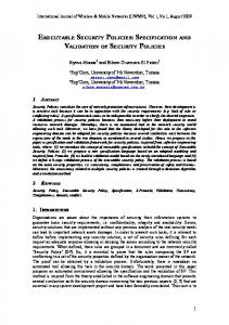
Since ESL automata are nondeterministic, we cannot translate them directly into Verilog. In this section, we describe how to synthesize automata into deterministic Mealy machines which can then be easily translated into Verilog programs. We proceed in two steps. First, we use a powerset algorithm to determinize the automata. Then, we use the variable markers to determine the inputs and outputs for each state of the Mealy machines. Since ESL automata do not have B¨uchi constraints, we use the traditional method for automata determinization by powersets which is described in many textbooks [25]. Although the algorithm Powerset is potentially exponential, the resulting automata in our experiments are often much smaller than the original automata. In Figure 6, results for 62 scripts in our PCI protocol specification are shown, where for each script, the ratio of the size of the deterministic automaton compared with that of the original non-deterministic automaton is shown. It can be seen that, in our experiments, the deterministic automata are always smaller than the nondeterministic automata. On avof their original size. The intuitive erage, the automata can be compressed to about explanation for this behavior is that the powerset algorithm clusters related states into one state. For the example in Figure 5, the automaton after determinization is shown in Figure 7. Since the deterministic automaton accepts the same language as the original
25%
111111111111111 000000000000000 000 111 000000000000000 111111111111111 0 1 111 000 00000000000000 11111111111111 000000000000000 111111111111111 0.5 0 1 000 111 00000000000000 11111111111111 0 1 111 000 0 1 000 111 111 000 0 1 0.4 000 111 1 0 111 000 0 1 000 111 1 0 111 000 0 1 0.3 000 111 1 0 000 111 1 0 111 000 0 1 000 111 1 0 111 000 0 1 0.2 111 000 0 1 000 111 1 0 111 000 0 1 111 000 1 0 0.1 000 111 0 1 111 000 0 1 000 111 1 0 000 111 0 1 0 000000000000000 111111111111111 111 000 0 1 000000000000000 111111111111111 0 000000000000000 111111111111111 1 20 40 60 1 000000000000000 111111111111111
Fig. 6. Compression obtained by determinization
:a
a; b a
�
� �
a ;b
�
a
Fig. 7. Automaton after determinization
automaton does, the behavior of the original scripts is maintained after determinization. Finally, we describe how to generate Mealy machines from deterministic automata. The Mealy machine model presented in the following definition takes into account the type concept which we use for traces. Definition 7. Mealy machine A Mealy machine M is a tuple hS; S0 ; I; O; �; Ri where S is a finite set of states, S0 � S is the set of initial states, I is a finite set of input variables, O is a finite set of output
=
:
variables (I \ O ;), � S � �I ! �O is the output function, and R � S � �I � S is the transition relation. M is deterministic if for every input � every state has a unique successor i.e., for all s; s0 2 S and � 2 �I , R s; �; s0 ^ R s; �; s00 ! s0 s00 . M accepts a trace T t1 t2 � � � over alphabet �I [ �O if there exists an infinite sequence S s1 s2 � � � of states such that (i) s1 2 S0 ; (ii) for all indices i, R si ; ti ; si+1 ; (iii) for all indices i, � si ; ti ti . The set of traces accepted by M is denoted by L M .
(
=
=
)
(
)
= ( umk( )
( umk( )) = mkd( )
( )
)
=
Given a deterministic automaton N hS; S0 ; ; �; F i, we generate a Mealy machine M hS; S0 ; I; O; �; Ri such that N and M have the same sets of states and initial states. Let MAX be the smallest number such that no state in N has more than MAX immediate successors. The input variables I of the Mealy Machine M are the unmarked variables of the automaton N , and the new variable nd, Dnd f ; : : :; MAXg. Intuitively, the new variable nd will be used to determine the successor state among the MAX possible successor states. The output variables O of M are the marked variables of N , i.e., O
. The output function � and the transition relation R are defined by the algorithm GenMealy shown in Figure 8.
=
= 1
= mkd( )
Algorithm GenMealy(N ) foreach s 2 S
0
P = umk(a) s0 S; �(s; a; s0 ) for each a P Q = b umk(b) = a; s0 S; �(s; b; s0 ) f
j 9
2
g
nd
= 0 _ :a
2
f
j
9
2
i=1 for each b 2 Q
� = � (s; a nd = i; mkd(b)) if �(s; b; s0 ) = true then R = R (s; a nd = i; s0 ) [f
^
[f
nd
g
^
=1
= 1^a
= 0^ = 1 _ :a=? nd
=0
= 0=fa�; b� g � nd = 1=a
s
0
2
nd
g
i=i+1 choose some b 2 Q for j=i to MAX
�=� R=R
nd
g
nd nd
s1
� a=b
Fig. 9. A deterministic Mealy machine
s; a nd = j; mkd(b)) s; a nd = j; s0 )
[ f(
[ f(
^
^
g
g
Fig. 8. Pseudo-code for GenMealy
Example 8. The Mealy machine obtained from the automaton in Figure 5 is shown in Figure 9.
nd is the new unconstrained internal signal. The labelling in state s2 denotes the input/output function, for example nd = 1=a� represents input nd = 1 and output is a� = 1.
Theorem 2. Let S be an ESL script. Then the language of the synthesized Mealy machine coincides with S on global variables. Formally,
Traces( ) clean(Traces(ModuleSynthesis(S ))) �gl Traces(S ):
M1
M2
Mealy Machine
v1 v2
Timeout@pci_master
Mealy Machine
v1 v2
FRAME_deassert lFRAME_@pci_master
Timeout
combine for combine for
v1
v2
Timer_count
Combiner
Timer@pci_master
Fig. 11. Identified Combinational dependency loops
Fig. 10. Combiners for a Module
The obtained Mealy machine can be translated into a Verilog program easily. Details are omitted due to the space restrictions. 4.3 Combiner generation Recall that each ESL script S is translated into a Mealy machine, and that different scripts can assign values to the same signal. In Section 2 we defined the operation 1 to combine two traces. As exemplified in Example 5, the operation 1 on traces is not the same as conjunction of scripts. On the level of Mealy machines, we introduce combiners which perform the operation 1 on traces. A combiner machine is defined as follows. Definition 8. Given a sequence M1 ; : : :; Mm of Mealy machines with possibly nondisjoint alphabets, the combiner C M1 ; : : :; Mm is a Mealy machine whose input alphabet is the union of the input alphabets of the Mi and whose output alphabet is obtained from the union of the output alphabets of the Mi by removing the marks. On input of a symbol �, C M1 ; : : :; Mm simulates each of the Mealy machines, collects the outputs o1 ; : : :; om of the Mealy machines, and nondeterministically outputs one element of comp o1 1 o2 1 : : : 1 om .
(
(
clean(
)
)
(
))
Thus, if the output of the Mealy machines is consistent, the combiner will output it; if it is inconsistent, then the combiner will output ffalseg; if the output does not determine the values of all signals, the combiner will nondeterministically choose consistent values for the unspecified or under-constrained signals. The algorithm Combine generates Verilog code for the combiner. In the Verilog translation, each Mealy machine is translated into a Verilog module. The combiner itself is a module which uses the Mealy machine modules as subprograms and combines their outputs. In the traditional approach (i.e., synthesizing the conjunction of all scripts), the number of tableau states for the conjunction of the scripts can become exponentially
larger. In fact, our techniques are tailored to find inconsistencies between scripts; in conjoined formulas, inconsistent behaviors would be eliminated. Finally, we can formally state the correctness of our algorithms, cf. Section 3.
= S1k � � �kSn be an ESL module. Then L(ModuleSynthesis(E )) �gl Traces(S1 ) 1 � � � 1 Traces(Sn ):
Theorem 3. Let E
4.4 Module Connection In Verilog, connecting the inputs and outputs of modules can be done hierarchically. For synchronous bus designs, combinational loops are not allowed. Therefore, in the variable dependency graph, we use standard algorithms for strongly-connected components [6] to identify combinational loops. Our tool will report combinational loops to the users. Figure 11 shows an example combinational loop identified during PCI bus protocol debugging. In the Figure, Timeout, lFRAME , and Timer are signals in module pci master, and FRAME deassert, Timer count and Timeout are names of scripts in this module. Each edge represents a dependency between the two signals introduced by the script, e.g., signal lFRAME depends on Timeout in script FRAME deassert.
5 Debugging Protocols in ESL For a protocol specified in ESL, it is essential to have debugging capabilities which verify that the specified protocol is indeed what the designers want to specify. In this section, we describe special properties of the generated Verilog and SMV code which facilitate debugging. Due to space restrictions, we describe only some of the debugging capabilities which we implemented. The code generator for Verilog and SMV can be extended easily to handle other capabilities. Synchronization Contradiction. In ESL, two scripts can potentially assert contradictory values to signals, cf. Example 5. To detect such cases, a flag OC is defined in the Verilog code for the combiner. As soon as the combiner computes f g, the flag is automatically set to . According to Theorem 3, the flag OC is set to if and only if the traces of the scripts contradict. Therefore, to verify the absence of synchronization . contradictions (i.e., consistency) it suffices to check for unreachability of OC Receptiveness. A machine is receptive [2] in an environment, if starting from any state, for all possible inputs from the environment, the machine can produce valid output and transit to a valid next state. Receptiveness is among the most important properties of protocols. In ESL, receptiveness questions arise on the level of modules. Receptiveness is interesting for a module in connection with the whole protocol, but also for a single module with unconstrained inputs. For each module M , a special flag BI M is defined in the Verilog code for M . If a Mealy machine belonging to M gets stuck, i.e., has no valid transition for the given input, then the flag BI M is set to . The absence of synchronization contradictions and the unreachability of BI M for each M guarantees the receptiveness of the ESL protocol. Deadend checks for receptiveness have been proposed previously for Moore machines in [23].
false 1
1
=1
1
Property Checking. The specification of protocols often can be partitioned into specifications of a fundamental and operational character, and another set of additional specifications which were logically redundant for a correct protocol, but are aimed at finding out if the protocol is correctly specified. In ESL, we build Verilog and SMV models based on the operational specifications, and then use a Verilog simulator and the SMV model checker to verify the additional specifications.
6 Experimental Results We have built a prototype system in Standard ML, which includes about 13,000 lines of code. To test the capability of our tool, we have specified a subset of PCI bus protocol [19]. The specification consists of 118 formulas and 1028 lines including English comments for each formula. The specification includes five module types: master sequencer, master backend, target sequencer, target backend, and arbiter. One master sequencer and one master backend form a PCI master; conversely, one target sequencer and one target backend form a PCI target. We have specified a biased random test bench [20] in the master backend, because in PCI, the test bench involves transaction request generation, which is an integral part of the behavior of the master backend. Using the parameter concept in ESL, the number of modules on the bus can be easily modified. Independently, [23] developed a specification methodology for the PCI protocol, in which explicitly declared signals are used for monitoring protocol violation. The specified subset of the PCI protocol includes burst transaction, master-initiated fast-back-to-back transaction, master and target termination conditions, initial and subsequent data latencies, target decode latency, master reissue of retried request. We are currently working on configuration cycles, bus parking and parity checking. We plan to specify the complete PCI bus protocol in future work. Our algorithm is very efficient, and it only takes about 15 seconds to generate the machine with SMV or Verilog model from 62 ESL scripts on a 550MHz Pentium 256 MB memory. The generated Verilog is about 7000 lines of code while the generated SMV is about 6100 lines of code. Using the Cadence Verilog-XL simulator, we are able to simulate the generated Verilog model. Many easy errors have been identified by checking synchronization contradiction in Verilog simulation, including some errors in the protocol. For example, the following two statements from [19] can be contradictory when a PCI target can perform fast decode.
III
1. In page 26, A PCI target is required to assert its TRDY# signal in a read transaction unconditionally when the data is valid. 2. In page 47, The first data phase on a read transaction requires a turnaround-cycle (enforced by the target via TRDY#). The sixty nine Verilog monitors from [24] are used to characterize correctness of the PCI bus protocol. In order to verify that our Verilog model is correct, we connect the monitors with our model to check whether our model violates the monitors. Model checking can formally verify the correctness of a given formula. However, it is limited by the size of the model. We use it on a limited configuration of the protocol,
namely one master, one target, one dummy arbiter. After abstracting the data path, e.g., the width of the bus, we have successfully model checked 70 temporal properties which are derived from the temporal properties given by [24]. The verification takes 450MB memory and 2 minutes on a 360MHz Sun 6500 Enterprise server.
7 Conclusions We have proposed a new logic ESL for formal specification of hardware protocols. Our synthesis methodology generates executable code in Verilog or SMV from ESL specifications. A significant part of the PCI bus protocol has been specified, simulated, and verified using our tool. Our experimental results clearly demonstrate that our synthesis methodology is feasible for systems of realistic complexity. In the future, we plan to complete the PCI bus specification and to experiment with other industrial bus protocols such as the IBM CoreConnect bus and the Intel P6 bus. To achieve this goal, we are investigating various extensions of ESL. In particular, we believe it is possible to incorporate our logic into Verilog without significantly changing the syntax of the language. Such an extension should also make our tool easier for engineers to use. Finally, we believe that game theoretic notions of consistency [10, 3] are necessary under certain circumstances. We intend to investigate various notions of consistency for our logic and devise algorithms for verifying them. Acknowledgment We are grateful to David Dill and Kanna Shimizu for discussions and comments on our paper, and for providing the PCI properties[24].
References 1. Y. Abarbanel, I. Beer, L. Gluhovsky, S. Keidar and Y. Wolfsthal,“FoCs - Automatic Generation of Simulation Checkers from Formal Specifications”, CAV 00: Computer-Aided Verification, Lecture Notes in Computer Science 1855, 538-542. Springer-Verlag, 2000. 2. R. Alur and T.A. Henzinger. Reactive Modules, Proceedings of the 11th Annual Symposium on Logic in Computer Science, 207-218. IEEE Computer Society Press, 1996. 3. R. Alur, T.A. Henzinger, and O. Kupferman. Alternating-time temporal logic. In Proc. 38th IEEE Symposium on Foundations of Computer Science, 100-109, 1997. 4. R. E. Bryant, P. Chauhan, E. M. Clarke, A. Goel. A Theory of Consistency for Modular Synchronous Systems. Formal Methods in Computer-Aided Design, 2000 5. P. Chauhan, E. Clarke, Y. Lu, and D. Wang. Verifying IP-Core based System-On-Chip Designs. In Proceedings of the IEEE ASIC Conference, 27-31, 1999. 6. T. Cormen, C. Leiserson, and R. Rivest. Introduction to Algorithm. MIT Press, 1990. 7. E. Clarke and E. Emerson. Synthesis of synchronization skeletons for branching time temporal logic. Logic of Programs: Workshop, Yorktown Heights, NY, May 1981 Lecture Notes in Computer Science, Vol. 131, Springer-Verlag. 1981.
8. E. Emerson and E. Clarke. Using branching time temporal logic to synthesize synchronization skeletons. In Science of Computer Programming, Vol 2, 241-266. 1982. 9. E. Clarke, O. Grumberg, and D. Peled. Model Checking. MIT Publishers, 1999. 10. David Dill. Trace Theory for Automatic Hierarchical Verification of Speed-independent Circuits. MIT Press, 1989. 11. M. Fujita and S. Kono. Synthesis of Controllers from Interval Temporal Logic Specification. International Workshop on Logic Synthesis, May, 1993. 12. D. Gabbay. The Declarative Past and Imperative Future: Executable Temporal Logic for Interactive Systems. In B. Banieqbal, B. Barringer, and A. Pnueli, editors, Temporal Logic in Specification, Vol. 398, 409-448. Springer Verlag, LNCS 398, 1989. 13. R. Gerth, D. Peled, M. Y. Vardi, and P. Wolper. Simple on-the-fly automatic verification of linear temporal logic. In Proc. 15th Work. Protocol Specification, Testing, and Verification, Warsaw, June 1995. North-Holland. 14. N. Halbwachs, J.-C. Fernandez, and A. Bouajjanni. An executable temporal logic to express safety properties and its connection with the language Lustre. In Sixth International Symp. on Lucid and Intensional Programming, ISLIP’93, Quebec City, Canada, April 1993. Universit’e Laval. 15. L. Lamport. The temporal logic of actions. ACM TOPLAS, 16(3):872–923, March 1994. 16. Z. Manna, P. Wolper: Synthesis of Communicating Processes from Temporal Logic Specifications, ACM TOPLAS, Vol.6, N.1, Jan. 1984, 68-93. 17. K.L. McMillan. Symbolic Model Checking. Kluwer Academic Publishers, 1993. 18. B. Moszkowski. Executing temporal logic programs. Cambridge University Press, 1986. 19. PCI Special Interest Group. PCI Local Bus Specification Rev 2.2. Dec. 1998. 20. J. Yuan, K. Shultz, C. Pixley, and H. Miller. Modeling Design Constraints and Biasing in Simulation Using BDDs. In International Conference on Computer-Aided Design. 584-589, November 7-11, 1999 21. A. Seawright, and F. Brewer. Synthesis from Production-Based Specifications. In Proceedings of the 29th ACM/IEEE Design Automation Conference, 194-199, 1992. 22. X. Shen, and Arvind. Design and Verification of Speculative Processors. In Proceedings of the Workshop on Formal Techniques for Hardware and Hardware-like Systems, June 1998, Marstrand, Sweden. 23. K. Shimizu, D. Dill, and A. Hu. Monitor Based Formal Specification of PCI. Formal Methods in Computer-Aided Design, 2000. 24. K. Shimizu. http://radish.stanford.edu/pci. 25. M. Sipser. Introduction to the Theory of Computation. PWS Publishing Company. 1997.