focus
requirements engineering
Executable Use Cases: Requirements for a Pervasive Health Care System Jens Bæk Jørgensen and Claus Bossen, University of Aarhus
any software experts argue that when we design a new system, we should create an explicit description of the environment in which the proposed system is to be used.1 The argument becomes crucial for pervasive computing,2 which aims to tightly integrate systems into their environments and into the work processes they’re to support. However, prototypes typically provide an explicit representation only of the system itself.
M
Executable use cases, on the other hand, can also describe the environment. EUCs are designed to ■
■
Narrow the gap between informal ideas about requirements and the formalization that eventually and inevitably emerges during system implementation Spur communication between users and system developers
Iterative prototyping is a feasible starting point to pursue these goals. But EUCs encom-
Using executable use cases, stakeholders can investigate system requirements interactively in the context of envisioned work processes. The authors illustrate EUCs on a pervasive health care system. 34
IEEE SOFTWARE
Published by the IEEE Computer Society
pass both iterative prototyping and explicit environment descriptions in terms of workflow modeling. This article describes a case study in which developers used EUCs to prototype an electronic patient record system for hospitals in Aarhus, Denmark. The first version of the EPR system was traditional and desktopbased. This caused at least two severe problems for its users, who spend most of their busy work days away from their offices (and thus from their PCs) and who are frequently interrupted. The first problem was immobility: In contrast to a paper-based record, an EPR can’t be easily transported. The second problem was time-consuming login and navigation: the EPR system required user ID and login to ensure information confidentiality and integrity, and logged-in users had to know 0740-7459/04/$20.00 © 2004 IEEE
how to navigate the system to do their clinical work—for example, to find a specific document for a patient. The new, envisioned pervasive health care system (PHCS),3 which has been prototyped but not yet deployed, strives to alleviate these two problems by ensuring users access to the EPR system wherever they need it and by making it easy to resume a suspended work process.
Executable use cases EUCs are based on UML-style use cases,4 with which PHCS stakeholders were already familiar via their involvement in the EPR project. An EUC consists of three tiers, which developers and users construct and execute iteratively (see Figure 1). Tier 1, the prose tier, contains prose descriptions of work processes and their proposed computer support. This tier represents everyday requirements engineering activities and is created routinely in many projects, often consolidated in the form of typical natural-language use cases. Ideally, Tier 1 is the result of domain analysis and collaboration among a broad range of users, system developers, and possibly other stakeholders in the initial pursuit of engineering a new system’s requirements. Tier 1 might even benefit from the participation of such professionals as anthropologists and sociologists. Tier 2, the formal tier, provides a formal, executable model of the work processes and their proposed computer support. You can use several different modeling languages at this stage—perhaps a programming language, or a graphical modeling language such as Harel’s statecharts, UML state machines or activity diagrams, or Petri nets. The case study we report here used a dialect of Petri nets. These languages differ in many ways—in particular, they have different degrees of formality and rigidity. However, they all support the modeling of states and actions. Each language has an execution semantics, ensuring that the actions that can happen in any given state, and the successor states that will be reached if certain actions take place, are relatively well defined. Tier 2 narrows the gap between informal ideas about requirements and the formalization present in the system implementation. Creating Tier 2 requires the effort of systems developers who are trained in creating formal, executable models in the chosen modeling language. The formal modeling process is fa-
Figure 1. The executable use case approach.
Tier 3 - Animation Insights User reponses
Tier 2 - Formal
Insights Tier 1 - Prose Insights Domain analysis
cilitated if one or more expert users with some flair for abstract thinking and logic can participate; in general, Tier 2 isn’t the average user’s domain. Tier 3, the animation tier, is a graphicalanimation interface to Tier 2. It represents the same work processes and their proposed computer support as Tier 2, but it uses only concepts, terminology, and graphics that users are familiar with and understand. Tier 3 supports communication between users and system developers, because building it requires joint efforts by these stakeholders to design and implement a fitting animation.
Support for specification, validation, and elicitation EUCs are an effective requirements engineering approach in conjunction with specification, validation, and elicitation. The resulting specification has a sound foundation because of Tier 2’s formality and unambiguity. EUCs support validation through execution. This is possible at Tier 2, but to understand what’s going on requires a technical expertise that often only system developers have. However, Tier 3 lets users be actively engaged in validation by investigating the consequences of the current specification—that is, the new work processes and their proposed computer support as realized at Tier 2. Elicitation is, in the same way as validation, supported through execution. When users interact with Tier 3, they’ll often encounter questions, find that EUCs behave in unexpected and perhaps inappropriate ways, or discover that relevant aspects of the proposed system haven’t been covered yet. In each such case, developers can revisit Tier 2’s formal model or users and deMarch/April 2004
IEEE SOFTWARE
35
Related Work For at least 15 years, the idea of augmenting prose use cases or scenarios with notions of execution, formality, and animation has been well established in the software industry. A usual prototype based on a prose sketch can be seen as an executable use case, with the formal tier created in a programming language and the animation tier being the application’s GUI. More recently, the execution and animation of requirements through formalization in various graphical modeling languages have gained attention, but often the systems considered are small—for example, the simple communication protocol described by Jeff Magee and his colleagues.1 In comparison, EUCs are immediately applicable to large real-world systems such as PHCS. David Harel and Rami Marelly also use the term executable use cases.2 This work deals with specifying reactive systems through an ingenious, intuitive way to automatically generate executable, formal models from scenarios. They use a calculator as the running example. In comparison, our EUC approach emphasizes explicit representation of the work processes the new system is to support. EUCs are a more mundane, manual approach, but this comes with important advantages—in particular that the interplay between an EUC’s three tiers not only supports but actually spurs communication.
References 1. J. Magee et al., “Graphical Animation of Behavior Models,” Proc. 22nd Int’l Conf. Software Eng. (ICSE 2000), ACM Press, 2000, pp. 449–508. 2. D. Harel and R. Marelly, “Specifying and Executing Behavioural Requirements: The Playin/Play-out Approach,” J. Software and System Modeling, Springer-Verlag, vol. 2, no. 2, July 2003, pp. 82–107.
velopers can look at Tier 1’s prose descriptions to try to find answers to the questions raised at Tier 3. As a result, they might remodel at Tier 2, rewrite at Tier 1, or do both to produce an improved version of the EUC.
Spurring of communication The EUC approach not only makes communication between disparate stakeholders possible, it can actually spur communication. This approach insists on three tiers and makes translation between the tiers explicit and visible. Creating Tier 1 forces users and developers to translate domain analysis into informal but explicit descriptions of new work processes and their proposed computer support. Tier 1 is often highly based on the users’ understanding of their existing work processes, so it’s largely a description of their domain. Creating Tier 2 forces the system developers to interpret, consolidate, and possibly expand the Tier 1 descriptions. Tier 2 explicitly represents the developers’ current interpretation of 36
IEEE SOFTWARE
w w w . c o m p u t e r. o r g / s o f t w a r e
Tier 1—that is, both the work processes and their proposed computer support. This is an important benefit beyond that of a typical prototype, which usually represents explicitly only the computer support (and where role playing or something similar is needed as a supplement to represent and simulate the work processes). Because Tiers 2 and 3 are consistent, users see the developers’ interpretation reflected when they interact with Tier 3. The users don’t have to care or even know about such uninviting computer concepts as states and actions. Thus, building Tier 1 spurs users and developers to communicate to agree on a prose description. Tier 2 spurs the developers to communicate with the users, because Tier 1’s ambiguities must be resolved, and missing but required pieces must be filled in. Interaction with Tier 3 spurs the users to communicate with the developers when a question arises. In this way, EUCs are a way for users and developers to detect misunderstandings and misconceptions. The “Related Work” sidebar compares EUCs with similar approaches.
PHCS design principles Although PDAs could solve the immobility problem mentioned earlier by providing wireless access to EPRs, this approach isn’t ideal because their screens are small and because they don’t fully address the time-consuming login and navigation problem. PHCS is a more ambitious solution and takes advantage of the possibilities of pervasive computing. The basic design principle for PHCS is context awareness: the system can register and react to certain context changes. Nurses, patients, beds, medicine trays, and other items are equipped with radio frequency identification (RFID) tags that let context-aware computers (near the medicine cabinet or patient beds, for example) automatically detect them. An accompanying design principle is that the system is propositional, in the sense that it makes qualified propositions, or guesses. Context changes can result in the automatic generation of buttons on a computer taskbar. Users must explicitly accept a proposition by clicking a button (they implicitly reject it by not clicking). The presence of a nurse holding a medicine tray for patient P in front of the medicine cabinet is a context that triggers the automatic generation of a button Medicine
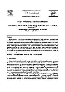
plan:P, because in many cases, the nurse now intends to navigate to P’s medicine plan. If the nurse clicks the button, she’s logged in and taken to P’s medicine plan. Guessing a user’s intention correctly from a given context is impossible to do all the time, and without the propositional principle, automatic short-cutting could become a nuisance because guesses would sometimes be wrong. Figure 2 outlines PHCS (we simplified and translated the interface into English for this article). The system’s current context is that nurse Jane Brown is pouring medicine for patient Bob Jones to take at 12 p.m. The medicine plan on the display shows which medicines have currently been prescribed (indicated by “Pr”), poured (“Po”), and given (“G”). You can see that the nurse has poured Sustac and Angettes but not yet Cuprofen for the 12 p.m. dose. Moreover, a taskbar button indicates that the medicine tray for another patient, Tom Smith, stands close to the computer.
Example EUC Let’s look at the three tiers of an EUC describing the work process medicine administration and its support by PHCS.
Figure 2. A simplified, English-translation version of the pervasive health care system interface.
Patient list: Jane Brown Medicine plan: Tom Smith Medicine Plan Name: Bob Jones Born: 10 Jan 1962 Date: 6 May 2003 Drug
Tab 8am 12pm 5pm 10pm
Sustac
1
G
Po
Pr
Pr
Angettes
2
G
Po
Pr
Pr
Cuprofen
1
G
Pr
--
--
automatically logged out again. This description captures just one specific combination of work subprocesses. There are numerous other scenarios to take into account, for example: ■ ■
■
Medicine may be poured for one or more patients. A nurse may approach the medicine cabinet without intending to pour medicine, but only to check an already filled medicine tray. Two or more nurses may administer medicine at the same time.
Prose tier Let’s say that nurse N wants to pour medicine into a cup on a medicine tray and give it to patient P. First, N goes to the medicine room. The buttons Login:N and Patient list:N appear on a context-aware computer’s taskbar when N approaches. If N clicks the second button, she’s logged in and a list of her assigned patients displays on the computer. A medicine tray is associated with each patient. When N takes P’s tray near the computer, the button Medicine plan:P appears on the taskbar, and a click makes P’s medicine plan (see Figure 2) appear on the display. N pours the prescribed medicine and acknowledges this in PHCS. When N leaves the medicine room, she’s automatically logged out. N now takes P’s medicine tray and goes to the ward where P lies in a bed that is equipped with a context-aware computer. When N approaches, the buttons Login:N, Patient list:N, and Medicine plan:P appear on the taskbar. If N clicks the last button, the medicine plan for P displays. Finally, N gives the medicine tray to P and acknowledges this in PHCS. When N leaves the bed area, she’s
The PHCS requirements must handle all these scenarios and many more. Creating detailed prose descriptions of additional scenarios and keeping track of dependencies and relationships between various scenarios are difficult, cumbersome, and error-prone. With respect to these issues, a formal model is a more appropriate representation.
Formal tier Tier 2 provides a formal model in Coloured Petri Nets,5 a mature and well-proven modeling language suitable for describing the behavior of large systems with characteristics such as concurrency, resource sharing, and synchronization. A CPN model resembles a board game, with rules that define how to play the game. The modeler’s task is to specify an appropriate board and playing pieces (tokens) to reflect the domain being modeled. We created and executed the medicine administration CPN model using the tool Design/CPN, which includes a graphical part and the programming language Standard ML. (After we did this project, the newer CPN Tools replaced Design/CPN.) March/April 2004
IEEE SOFTWARE
37
(nurse,trays) (compid,display,taskbar,users)
Approach medicine cabinet
(compid,display, addMedicineCabinetButtons nurse taskbar, users) HS tray Pour/check Trays by medicine cabinet tray
(nurse,trays) (JaneBrown,notrays)
TRAY (MaryGreen,notrays) (nurse,trays) By medicine cabinet
Ready
NURSE
NURSE
(nurse,trays) (compid,display,taskbar,users) Medicine cabinet computer COMPUTER (compid,display, removeLoginButton nurse taskbar, addUser nurse users)
Enter EPR via login button (nurse,trays)
[loginAllowed nurse (compid,display, taskbar,users)]
(1,blank, nobuttons, nousers)
(compid,display,taskbar,users) Leave medicine cabinet if loggedin nurse (compid,display,taskbar,users) then (compid, blank, removeMedicineCabinetButtons nurse taskbar, removeUser nurse users) else (nurse,trays) (compid, display, removeMedicineCabinetButtons nurse taskbar, users)
Figure 3. A sample formal tier (Tier 2) module in the medicine administration EUC.
38
IEEE SOFTWARE
A CPN model is structured as a set of welldefined, interrelated modules; for example, our medicine administration CPN model consists of 11 modules. Here, we’ll focus on the module that models the pouring and checking of medicine on trays (see Figure 3). A CPN model describes a system’s states and actions. A CPN model’s state is a distribution of tokens on places, drawn as ellipses. Each place has a data type (its “color”), written in italic capital letters, which determines the kinds of tokens the place may contain. In Figure 3, the nurses are modeled by tokens on the places Ready and By medicine cabinet, which both have data type NURSE. A token on Ready corresponds to a nurse who is ready to perform work, and a token on By medicine cabinet models a nurse who is in the medicine room—for example, pouring medicine. The Trays by medicine cabinet place is used to model keeping track of the medicine trays. A token on the Medicine cabinet computer place models the medicine cabinet computer. The state shown in Figure 3 represents that the nurses Jane Brown and
w w w . c o m p u t e r. o r g / s o f t w a r e
Mary Green are ready and have no trays. The computer has a blank display and no taskbar buttons or users, and no trays are nearby. A CPN model’s actions are represented using transitions, drawn as rectangles. In Figure 3, the transitions correspond to nurses’ actions. Arcs connect transitions with places. The model’s actions consist of transitions that remove tokens from input places and add tokens to output places. The expressions associated with the arcs determine the removed and added tokens; for example, the expression (nurse,trays) on the arc from the Ready place to the Approach medicine cabinet transition specifies a NURSE token. The execution semantics for CPN models is defined by the concepts enabling and occurrence. A transition that is ready to remove and add tokens is said to be enabled. The basic condition for enabling is that appropriate tokens are present on the input places. In Figure 3, enabling of the transition Approach medicine cabinet requires that the place Ready contain some NURSE token and the place Medicine cabinet computer contain some COMPUTER
Department Ward
Bath
Team room
Ward
Provide trays Pour/check trays Give medicine
Ward
Medicine room
Medicine room
Bath
Ward
Take tray
Patient list: Jane Brown Login: Jane Brown
Leave medicine cabinet
Bob Jones
Ward
Figure 4. A simplified,
token. Thus, Approach medicine cabinet is enabled in the shown state (none of the other transitions are). An enabled transition may occur. If Approach medicine cabinet does occur, it’s modeling a nurse changing from being ready to being busy near the medicine cabinet. The model updates the token on the Medicine cabinet computer place to reflect that a login button and a patient list button have been added to the taskbar, as captured by the function addMedicineCabinetButtons used in the arc expression. Three transitions model the possible actions for a nurse who is near the medicine cabinet. Pour/check tray is a special kind of transition that refers to another module of the model (not shown), which models the details of pouring and checking of a single tray. The Enter EPR via login button transition models that a nurse clicks on the login button and makes a general-purpose login to EPR. The Leave medicine cabinet transition models the effect of a nurse leaving: The corresponding to-
ken is put back on the Ready place, and the English-language COMPUTER token is changed to reflect the Med- version of the animation icine cabinet computer’s new state. tier (Tier 3) in the medicine administration EUC.
Animation tier Tier 3 is an interface to the CPN model— that is, the graphical animation reflects the states, actions, and state changes that appear when the model is executed. The model and the animation are linked in that occurrences of transitions call drawing functions, which trigger the creation, movement, or deletion of graphical objects (such as nurse icons) in the animation. Figure 4 shows the animation tier of the medicine administration EUC. Like the formal tier, the animation tier is created and executed with the Design/CPN tool, which includes a library for creating animations. The animation runs in three windows. The Department window shows the layout of a hospital department with wards, the medicine room, the so-called team room (the nurses’ office), and two bath-
March/April 2004
IEEE SOFTWARE
39
The same cost-benefit considerations apply— for example, trade-offs between the degree of coverage and the number of users involved versus the required time investment.
rooms. The Medicine room window shows the medicine cabinet, pill boxes, tables, medicine trays, and the computer screen (enlarged). The Ward window shows a patient, a bed, a table, and the computer screen. Thus, the Department window gives an overview, and the other windows zoom in on areas of interest. The animation is interactive in the sense that the Tier 3 user is prompted to make choices. In Figure 4, the animation shows that nurse Jane Brown is in the medicine room, shown in the Department window and the Medicine room window, sufficiently close to the context-aware computer to produce the two taskbar buttons Patient list: Jane Brown and Login: Jane Brown at the computer. The two shaded ellipses, named Take tray and Leave medicine cabinet, on the far right in the Medicine room window correspond to possible actions in the nurses’ work process. The user may choose one of these buttons to drive the animation further. The user can also select one of the taskbar buttons at the computer. For example, if the user pushes the Leave medicine cabinet button, this forces the transition with the same name in the Tier 2 CPN model (shown in Figure 3) to occur. As a result, the user sees the nurse walk away from the medicine cabinet and the taskbar buttons disappear from the computer screen. If the user pushes the Take tray button and then selects Bob Jones’ medicine tray, the tray is moved close to the computer, and a medicine plan button for Bob Jones appears on the taskbar. If the user pushes this button, the computer will display a screen like the one in Figure 2.
The EUC as requirements specification The EUC specifies many requirements for PHCS. With the Tier 2 CPN model, the developers have precisely specified system requirements using transitions that model manipulation of the involved computers. You must take into account each transition connected to the places that model the computers. The following sample requirements are specified by transitions, as Figure 3 shows: R1: When a nurse approaches the medicine cabinet, the medicine cabinet computer must add a login button and a patient list button for that nurse to the taskbar (transition Approach medicine cabinet). R2: When a nurse leaves the medicine cabinet, if 40
IEEE SOFTWARE
w w w . c o m p u t e r. o r g / s o f t w a r e
she is logged in, the medicine cabinet computer must blank off its display, remove the nurse’s login button and patient list button from the taskbar, and log her out (transition Leave medicine cabinet). R3: When a nurse selects her login button, she must be added as a user of EPR, and the login button must be removed from the computer’s taskbar (transition Enter EPR via login button). You could specify R3 using a usual prototype. However, such a prototype would only explicitly capture the users’ interaction with the system itself; to properly specify R1 and R2, which refer to actions in the environment, you’d need some description of the environment. As Figure 4 shows, an EUC explicitly puts the requirements into context. A typical prototype explicitly represents only the computer screens shown in the Medicine room and Ward windows.
Evaluation The EUC we’ve presented is the result of a number of iterations, each version based on feedback on the previous version. The initial prose tier emerged from domain analysis (in the form of ethnographic field work) and a series of vision workshops with participation of nurses, doctors, computer scientists, and an anthropologist. We also discussed the EUC in evaluation workshops with nurses from various departments in Aarhus hospitals and with personnel from the software company that’s involved in the PHCS project. The visual representation using familiar symbols in the animation tier enabled the nurses to readily participate in discussions. They could immediately focus on the relevant subject matter, the work process, and its computer support without being concerned with technical, to-them-irrelevant details concerning the chosen modeling language. They appreciated the opportunity to investigate a new work process in a trial-and-error fashion. In particular, the nurses said that the EUC’s explicit description of the environment and the new work process made them think of a broad set of requirements issues. Some of the scores of questions and issues raised would also have emerged naturally using a typical prototype, but many others, as with specification, rely on the presence of an
explicit description of the environment and the work process. Here are three examples of such questions and their corresponding answers: ■
■
■
What happens if two nurses are both close to the medicine cabinet computer? The computer generates login buttons and patient list buttons for both of them. What happens when a nurse carrying multiple medicine trays approaches a bed computer? In addition to a login button and a patient list button for that nurse, only one medicine plan button is generated—a button for the patient associated with that bed. Can one nurse acknowledge pouring medicine for a given patient while another nurse at the same time acknowledges giving medicine to that same patient? No, that would require a more fine-grained concurrency control exercised over the patient records.
A
lthough the EUC approach applies immediately to requirements engineering for pervasive and other kinds of interactive systems, further research issues should be investigated, particularly the tough, crucial question asked by any practitioner involved in real projects: Are the person-hours spent on Tiers 2 and 3 justified by the benefits obtained? Regarding the medicine administration EUC, Tier 1 was expensive, while Tiers 2 and 3 were comparatively cheap. Tier 1 involved a broad range of stakeholders, consuming relatively many person-hours. The time consumption at Tier 2 benefited from Tier 1 work being quite thorough even before the first version of Tier 2 was created, and from a user being able to participate in the formal modeling. The time consumption at Tier 3 benefited from the availability of skilled users, many already trained to communicate with software developers through their involvement in the EPR project, and all of them eager to discuss possible solutions to the problems caused by introducing the EPR system. Perhaps we were a bit lucky here; health care personnel aren’t always enthusiastic about IT solutions.6 General cost-benefit analyses are difficult, and our observations on PHCS, of course, don’t immediately carry over to other projects.
About the Authors Jens Bæk Jørgensen is an assistant professor at the University of Aarhus, Denmark. His research focuses on requirements engineering, modeling, and distributed and pervasive computing. He participated in Aarhus’ electronic patient record project when he previously worked as a systems engineer at one of the software companies involved. He received his PhD in computer science, with special emphasis on Coloured Petri Nets, from the University of Aarhus. Contact him at the Dept. of Computer Science, Univ. of Aarhus, IT-parken, Aabogade 34, DK-8200 Aarhus N, Denmark;
[email protected].
Claus Bossen is an associate professor at the Institute of Information and Media Sci-
ence, University of Aarhus, and is associated with the Centre for Pervasive Health Care, Denmark. His research focuses on the relationships among IT, work processes, and organizations, and more specifically on the use of IT, especially pervasive computing, in health care. He is currently doing ethnographic field work on developing and implementing electronic patient records in Danish hospitals. He received his PhD in anthropology from the University of Aarhus. Contact him at Information and Media Sciences, Univ. of Aarhus, Helsinforsgade 14, DK-8200 Aarhus N, Denmark;
[email protected].
However, in general, adding and applying Tiers 2 and 3 are comparable to usual iterative prototyping. The same cost-benefit considerations apply—for example, trade-offs between the degree of coverage and the number of users involved versus the required time investment. So, given the industry’s acceptance and use of iterative prototyping, we believe that using EUCs will be cost-effective.
References 1. S. Lauesen, “Task Descriptions as Functional Requirements,” IEEE Software, vol. 20, no. 2, Mar./Apr. 2003, pp. 58–65. 2. M. Weiser, “The Computer for the 21st Century,” Scientific Am., vol. 265, no. 3, Sept. 1991, pp. 94–104. 3. H. Christensen and J. Bardram, “Supporting Human Activities—Exploring Activity-Centered Computing,” UbiComp 2002: 4th Int’l Conf. Ubiquitous Computing, LNCS 2498, Springer-Verlag, 2002, pp. 107–116. 4. A. Cockburn, Writing Effective Use Cases, AddisonWesley, 2000. 5. L. Kristensen, S. Christensen, and K. Jensen, “The Practitioner’s Guide to Coloured Petri Nets,” Int’l J. Software Tools for Technology Transfer, vol. 2, no. 2, 1998, pp. 98–132. 6. L. Cysneiros, “Requirements Engineering in the Health Care Domain,” Proc. Requirements Eng. (RE 02), IEEE CS Press, 2002, pp. 350–356.
For more information on this or any other computing topic, please visit our Digital Library at www.computer.org/publications/dlib.
March/April 2004
IEEE SOFTWARE
41