Execution Performance of the Scheduled Dataflow Architecture (SDF) Joseph M. Arul Dept. of Electrical and Computer Engineering University of Alabama in Huntsville Huntsville, AL 35899 e-mail:
[email protected] Abstract This paper presents an evaluation of a nonblocking, decoupled memory/execution, multithreaded architecture known as the Scheduled Dataflow (SDF). Recent focus in the field of new processor architectures is mainly on VLIW (e.g. IA-64), superscalar and superspeculative designs. This trend allows for better performance at the expense of increased hardware complexity, and possibly higher power expenditures resulting from dynamic instruction scheduling. This research deviates from this trend by exploring a simpler, yet powerful execution paradigm that is based on dataflow and multithreading. A program is partitioned into nonblocking execution threads. In addition, all memory accesses are decoupled from the thread’s
1. Introduction The performance gap between processors and memory has widened in the past few years and the trend appears to continue in the foreseeable future. Multithreading has been touted as a solution to minimize the loss of CPU cycles by executing several instruction streams simultaneously. It is necessary to find an appropriate multithreaded model and implementation to achieve the best possible performance. The use of non-blocking dataflow based threads are appropriate for improving the performance of Superscalar architectures. SDF architecture differs from other multithreaded architectures in two ways: i) The programming paradigm is based on dataflow, which eliminates the need for complex runtime scheduling, thus reducing the hardware complexity significantly, and ii) complete decoupling of all memory accesses from execution pipeline. The underlying dataflow and non-blocking models of execution permit a clean separation of memory accesses (which is very difficult to coordinate in other programming models). Data is pre-loaded into an enabled thread’s register context prior to its scheduling on the execution pipeline. After a thread completes execution, the results are post-stored
execution. Data is pre-loaded into the thread’s context (registers), and all results are post-stored after the completion of the thread’s execution. While multithreading and decoupling are possible with control-flow architectures, we believe that the non-blocking and functional nature of SDF, make it easier to coordinate the memory accesses and execution of a thread, as well as eliminate unnecessary dependencies among instructions. In this paper we compare the execution cycles required for programs on SDF with the execution cycles required by programs on SimpleScalar (a Superscalar simulator). Keywords: Multithreaded architectures, Dataflow architectures, Superscalars, Decoupled Architectures, Memory latency.
from its registers into memory. The instruction set implements dataflow computational model, while the execution engine relies on control-flow like sequencing of instructions. Unlike Superscalar and VLSI architectures, proposed architecture performs no (dynamic) Out-of-order execution and thus eliminates the need for complex instruction scheduling hardware. The hardware savings in this architecture can be utilized to include either more processing units on a chip or more register sets to increase the degree of multithreading (i.e., thread level parallelism). For this architecture, definition of the instruction set and an instruction level simulator has been developed. Several programs have been translated and compared the execution performance of this architecture with that of conventional scalar RISC processors using DLX simulator [Hennessy96].
2. The Scheduled Dataflow Processor To describe the “scheduling” of instructions in this architecture, the example below presents how the Scheduled Dataflow (SDF) code look like. A pair of register consists of even-odd registers. For example, RR2 refers to registers R2 and R3 within a specified thread context. The two source operands
destined for a SDF instruction are stored in the pair of registers assigned to that instruction – data is stored in either the left or right half of a register pair by a predecessor instruction. The instruction is not scheduled for execution immediately when the operands are matched. Instead, operands are saved in the register-pair associated with the instruction and the enabled instruction is scheduled for execution at a later time. Thus it eliminates the asynchronous execution implied by dataflow method. ADD RR2, R4, R6 NEG RR4, R9, R12 SUB RR6, R14, R17 Assuming that registers R2 and R3 contain the source operands for ADD, when scheduled, the instruction ADD RR2, R4, R6 adds the contents of these two registers R2 and R3, and stores the result in R4 and R6. Register R4 is one (and only one) of the source operands for NEG instruction. Likewise the operands for SUB are stored in the pair R6, R7. Registers R9, R12, R14, R17 indicate the destinations for the results generated by NEG and SUB instructions. The above instructions still retain the functional nature of dataflow – data flows from instruction to instruction and there are no write-after-read (WAR or conceptually equivalent anti-) and write-after-write (WAW or equivalent output -) dependencies. Our deviation is from token driven models of previous dataflow implementations. We use “instruction driven” paradigm by scheduling instructions. Compile time analyses of dataflow graphs are used to achieve instruction scheduling. The code shown above is for the Execution Pipeline (EP). Since our architecture is a decoupled multithreaded system, we use two separate units: Synchronization Pipeline (SP) and Execution Pipeline (EP). SP is responsible for scheduling enabled threads on EP, preloading threads’ context (ie., registers) with data from the threads’ Frame memories, and poststoring results from a completed threads’ registers in Frame memories of destination threads. The preload context can be explained from the following codes for the above code shown previously. Assume that the above code block receives two inputs for ADD from other threads. Each thread will be associated with a frame and the inputs to the thread are saved in the frame until the thread is enabled for execution (based on its synchronization count, as described later).
When enabled, a register context is allocated to the thread and the input data for the thread from its frame memory is “preloaded” into its registers. LOAD RFP|2, R2 LOAD RFP|3, R3 Assuming that the inputs for the thread (or ADD instruction) are stored in its (frame) reference frame pointer (RFP) at offsets 2 and 3, the above code (executed by SP) preloads the thread data into registers and schedules the thread on EP. The EP then uses only its registers during the execution of the thread body as shown above. Consider that the result generated by SUB in our code example (in R17) is needed by some other thread. The frame pointer and a frame-offset for the destination thread are made available to the current thread in registers. STORE R17, R32|R35 This instruction transfers (or post-stores) the result of the current thread (i.e., from SUB, in R17) to a frame pointed to by R32 at a frameoffset contained in R35. SP performs all stores after a thread completes its execution at EP. 2.1 Execution Pipeline
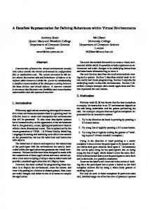
Figure 1 shows the block diagram of the execution pipeline (EP). Remember that EP executes computations of a thread using only registers. Instruction fetch unit behaves like a traditional fetch unit, relying on a program counter to fetch the next instruction. We rely on compile time analysis to produce the code for EP so that instructions can be executed in sequence and assured that the data for the instruction is already available in its pair of source registers. The information in the Register context can be viewed as a part of a thread’s continuation: , where FP refers to a register file assigned to the thread during its execution. Decode (and register fetch) unit obtains a pair of registers that contains (up to) two source operands for the instruction. Execute unit executes the instruction and sends the results to write-back unit along with the destination register numbers. Writeback unit writes (up to) two values to the register file. As can be seen, the Execution Pipeline (EP) behaves more like a conventional pipeline while retaining the primary dataflow properties; data flows from instruction to instruction. Moreover, the EP does not access data cache memory, and hence require no pipeline stalls (or context switches) due to cache misses.
In str uctio n C ach e
D eco de Un it
In stru ction Fetch U n it
E x ecute U nit
W rite-B ack U nit
PC
Pr e-Lo ad ed Th read s
R e gist er Se ts
Reg . Co n tex t
Fig 1. General Organization of Execution Pipeline (EP) 2.2 Synchronization Pipeline Figure 2 shows the organization of the primary pipeline of the synchronization Processor (SP). SP deals with pre-load and poststore instructions. The pipeline consists of the following stages: Instruction Fetch unit fetches an instruction belonging to the current thread using PC. Decode unit decodes the instruction and fetches register operands (using Register Context). Effective
address unit computes effective address for memory access instructions. LOAD and STORE instructions only reference the frame memories of threads, using a frame-pointer (FP) and an offset into the frame; both of which are contained in registers. Memory access unit completes LOAD and STORE instructions. Pursuant to a post-store, the synchronization count of a thread is decremented. Execute unit decrements synchronization counts. Finally, Write-Back unit completes LOAD (pre-load).
D ata Cach e In str uctio n Cach e In str uctio n F etch U n it En ab led Th read s
Po st-S to re Th read s
D eco d e E ffectiv e U n it A dd ress U nit
M emo ry Access U n it
E xecu te U n it
W rite-B ack U n it
PC
R eg . Co n tex t
R e g iste r S e ts
Fig 2. The synchronization Pipeline. In addition to accessing memory (for preload and post-store), Synchronization Pipeline (SP) holds thread continuations awaiting inputs and allocates register contexts for enabled threads. In our architecture a thread is created using a FALLOC instruction. FALLOC instruction creates a frame and stores instruction pointer (IP) of the thread and its synchronization count (Synch Count) indicating the number of inputs needed to enable the thread. When a thread completes its execution and "post-stores" results (performed by SP), the synchronization counts of awaiting threads are decremented. An enabled thread (when the Synch Count becomes zero) is scheduled by allocating a
register context to it, and “pre-loading” the registers from its Frame memory. In order to speed up frame allocation, SP pre-allocates fixed sized frames for threads and maintains a stack of indexes pointing to the available frames. The execution processor (EP) pops an index from the stack and uses it as the address of the frame (i.e., FP) in response to a FALLOC instruction. SP pushes de-allocated frames when executing FFREE instruction subsequent to post-stores of completed threads. The register sets (Reg. Context) are viewed as circular buffers for assigning (and de-allocating) to enabled threads. These policies permit for fast context switch and creation of threads. A thread moves from “pre-
load” status (at SP), to “execute” status (at EP) and finishes in “post-store” status (at SP). We use FORKSP to move a thread from EP to SP and FORKEP to move a thread from SP to EP. FALLOC and FFREE take 2 cycles in our architecture. FORKEP and FORKSP take 4
cycles to complete. This number is based on the observations made in Sparcle [Agarwal 93] that a 4 cycle context switch can be implemented in hardware. The scheduler unit is responsible for determining when a thread becomes enabled and allocating a register file to the enabled thread.
W a itin g T h r e a d s FP
Reg . Co n tex t
IP
Po s t- St o r e T h r e ad s FP
IP
S y n ch C o u nt
En ab led Th read s Reg . C on tex t
IP
S P P ip elin e
P ri or ity C o nt ro l
S ched u ler A v ai la b le Fr a m e s
P relo ad ed Th read s
Fig 3. Overall organization of the SP. Scheduler will also be responsible for scheduling preload and post-store threads on multiple SPs and preloaded threads on multiple EPs in Superscalar implementations of this architecture. The scheduling is at thread level in this system rather than at instruction level as done in other multithreaded systems thus requiring a simpler hardware.
3. Evaluation of the Decoupled Scheduled Dataflow Architecture In this paper, execution of generated code for actual programs using the instruction simulator will be presented. Currently, the simulator assumes a perfect cache (viz., all memory accesses take one cycle). Comparison of SDF with a Superscalar architecture with multiple functional units and Out-of-Order instruction issue logic as facilitated by Simplescalar Tool Set [Burger 97] will be presented. The effect of thread granularity (average run-lengths of the execution threads on EP) on the performance of the SDF will be presented. Besides the performance gained by increasing the number of SPs and Eps (that is, Superscalar-SDF), as compared to the performance with that of conventional Superscalar processors were measured. The programs used for this study include a Matrix Multiply, FFT, Zoom [Terada 99] and Fibonacci.
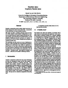
Due to lack of space in this paper, only the FFT data will be presented. For FFT (Table 1), 8 threads were used for SDF. Data sizes of 256 or larger, the available thread level parallelism in SDF (and the overlapped execution of SP and EP) exceeds the available instruction level parallelism; leading to a better performance by SDF. The data is in line with the studies performed on Simultaneous Multithreading ([Mitchell 99], [Lo 97]), which indicate that high performance is achieved by using a combination of thread level and instruction level parallelism. The figure 4 below plots execution time in cycles for different data sizes. SDF performs better than all other architectures. SDF does not perform any dynamic instruction scheduling, eliminating complex hardware (e.g., Scoreboards or reservation stations). Moreover, Simplescalar utilizes branch prediction (the data shown uses Bimodal prediction with 2048 entries). At present SDF uses no branch prediction. The data thus far confirms that any multithreaded architecture requires greater thread level parallelism to achieve good performance; Superscalar architecture requires greater instruction level parallelism. The non-blocking model is better suited for decoupling memory accesses from execution unit. Since SDF uses two different types of pipelines (SP and EP), it is
necessary to achieve a good balance of utilization between these two units. This could be achieved using good compiler optimizations Data Size
and speculative executions using static branchpredictions, to increase the run-lengths of threads executing on EP.
SDF
Superscalar Superscalar Out of In Order Order 13791 21423 14294 33635 37917 25608 79895 83024 53595 185765 212301 132479 424411 604674 364203 955721 1095955 1906115 2126583 6453376 3576399
8 16 32 64 128 256 512
SDF/IO
SDF/OO
0.6437 0.8870 0.9623 0.8750 0.7018 0.5013 0.3295
0.9648 1.3134 1.4907 1.4022 1.1653 0.8720 0.5946
Table 1. SDF Vs. Superscalar (FFT) S D F v s . S u p e rs c a la r (F F T ) 7000000
Execution Cycles
6000000 5000000 SDF
4000000
In O d e r 3000000
O u t o f O rd e r
2000000 1000000 0 8
16
32
64
128
256
512
D a t a S iz e
Fig 4. Comparing SDF with Superscalar Processors for FFT (using Simplescalar Tool Set) 3.1 Execution Performance of SDF with multiple SPs and EPs The main benefits of SDF can be seen when multiple SPs and EPs compare the performance with Superscalar architectures using multiple integer and Floating-Point units. The conventional Superscalar systems do not scale well with increasing number of functional units and the scalability is limited by the instruction fetch/decode window size and the RUU size.
4. Conclusion In this paper a non-blocking multithreaded dataflow architecture that utilizes control-flow like scheduling of instructions as well as separate memory accesses from instruction execution to tolerate long latency operations has been presented. When the thread level parallelism is high, SDF substantially outperforms Superscalar architectures (with multiple functional units) using In-Order instruction execution. SDF under-performs Superscalar architectures with Out-of-Order execution, when the instruction level parallelism is high but thread level parallelism is low. SDF
SDF relies primarily on thread level parallelism, and the decoupling of memory accesses from execution. SDF performance can scale better with a proper balance of workload among SPs and EPs. Superscalar system, the Instruction Fetch and Decode window widths are set to 32 and RUU size to 32. When the window width is increased beyond 32 and RUU size is set to 64, the performance of Superscalar showed less than 5% improvements. reduces the complexity of the processor by eliminating the need for complex logic (e.g., scoreboard or reservation stations [Hennessy 96]) needed for resolving data dependencies, register renaming, Out-of-Order instruction issue and branch predictions. Definitely decoupled access/execute implementations are possible within the scope of conventional architectures; multithreading model presents greater opportunities for exploiting the separation of memory accesses from execution pipeline. Even among multithreaded alternatives, non-blocking models are more suited for the decoupled execution.
5. References [Agarwal 93] A. Agarwal, et al. "Sparcle: An evolutionary processor design for multiprocessors", IEEE Micro, pp 4861, June 1993. [Bohm 91] A. D. W. Bohm, D. C. Cann, J. T. Feo, and R. R. Oldehoeft. “SISAL Reference Manual: language version 2.0”, Tech, Report CS91-118, Computer Science Dept., Colorado State University. [Burger 97] D. Burger and T. M. Austin. "The SimpleScalar Tool Set Version 2.0", Tech Rept. #1342, Department of Computer Science, University of Wisconsin, Madison, WI. [Culler 90] D.E. Culler and G.M. Papadopoulos. "The explicit token store", Journal of Parallel and Distributed Computing, 10(4), pp 289-308, 1990 [Dennis 80] J.B. Dennis. "Dataflow Supercomputers", IEEE Computer, Nov. 1980, pp 48-56. [Giorgi 99] R. Giorgi, K. M. Kavi, H. S. Kim, “Scheduled Dataflow Instruction Manual”, Dept. of Electrical and Computer Engineering, UAH. http://crash.eb.uah.edu/~kavi/Research/ sda.pdf [Grunewald97] W. Grunewald, T. Ungerer. “A Multithreaded Processor Design for Distributed Shared Memory System,” Proc. Int’l Conf. on Advances in Parallel and Distributed Computing, 1997. [Hennessy96] J.L. Hennessy, and D.A. Patterson. Computer Architecture: A Quantitative Approach, Morgan Kaufmann Publisher, 1996. [Hum 95] H.H.-J. Hum et al. "A Design Study of the EARTH Multiprocessor,’’ Proceedings of the Conference on Parallel Architectures and Compilation Techniques (PACT), Limassol, Cyprus, June 1995, pp. 59-68. [Iannucci88] R.A. Iannucci. "Toward a dataflow/von Neumann hybrid architecture", Proc. of 15th symposium on Computer Architecture (ISCA-15), pp 131-140, 1990. [kavi 00] K. M. Kaiv, R. Giorgi and J. Arul. “Comparing execution performance of Scheduled Dataflow Architecture with RISC processors” Proc. Of the 13th ISCA Parallel and Distributed Computing systems Conference (PDCS-00), Published by the
International Society of Computers and their Applications, Las Vegas, Aug. 810, 2000. pp 41-47. [Lam 92] M. Lam and R.P. Wilson. "Limits of control flow on parallelism", Proc. of the 19th Intl. Symposium on Computer Architecture (ISCA-19), pp 46-57, May 1992. [Lo 97] J.L. Lo, et al. "Converting thread-level parallelism into instruction-level parallelism via Simultaneous Multithreading", ACM ransactions on Computer Systems, Aug. 1997, pp 322354. [Mitchell99] N. Mitchell, L. Carter, J. Ferrante and D. Tullsen. "ILP vs TLP on SMT", Proc of Supercomputing’ 99. [Papadopoulos91] G.M. Papadopoulos and K.R. Traub: (1991). "Multithreading: A Revisionist View of Dataflow Architectures," Proceedings of the 18th International Symposium on Computer Architecture (ISCA-18), pp. 342-351. [Papadopoulos90] G.M. Papadopoulos and D.E. Culler. "Monsoon: An explicit tokenstore architecture", Proc. of 17th Intl. Symposium on Computer Architecture (ISCA-17), pp 82-91, May 1990. [Saulsbury 96] A. Saulsbury, F. Pong and A. Nowatzyk. "Miss the memory wall: the case for processor/memory integration", Proc of ISCA, May 1996 [Shankar 95] B. Shankar, L. Roh, W. Bohm and W. Najjar. "Control of parallelism in multithreaded code", Proc of the Intl Conference on Parallel Architectures and Compiler Techniques (PACT-95), June 1995. http://www.cs.colostate.edu /~dataflow/papers/pact95b.pdf. [Smith 82] J.E. Smith. “Decoupled Access/Execute Computer Architectures”, Proc of the 9th Annual Symp on Computer Architecture, May 1982, pp 112-119. [Terada99] H. Terada, S. Miyata and M. Iwata. “DDMP’s: Self-timed super-pipelined data-driven multimedia processor”, Proceedings of the IEEE, Feb. 1999, pp. 282-296 [Tsai 99] J. Y. Tsai, J. Huang, C. Amlo, D. Lilja, and P. C. Yew. “The Superthreaded processor architecture”, IEEE Trans. on Computers, Sept. 1999, pp. 881-902.