Experiences of Any Source and Source Specific Multicast Implementation in Experimental Network Milan Simek^ Radim Burget^ and Dan Komosny^ * Department of Telecommunications Brno University of Technology Brno, Czech Republic simek.milfg),phd.feec.vutbr.cz, (burget,
[email protected]
Abstract. Any Source Multicast (ASM) called Internet Standard Multicast (ISM) and its extension. Specific Source Multicast (SSM), are two known multicast technologies for delivering a data flow to a great number of customers over IP networks without cumulative bandwidth consumption. ASM technology is suitable for the many-to-many delivering model such as videoconferencing, where more sources are sending the traffic to one multicast group. SSM technology was developed as a solution for one-to-many delivering model such as the Internet Protocol Television (IPTV), where the receiver exactly defines the source of the multicast traffic. ASM and SSM can co-operate together on the network if specific conditions are complied with. The paper deals with describing the experiences and the measurement results from the implementation of these two multicast technologies in an experimental network. Keywords: Any Source Multicast, Specific Source Multicast, Protocol Independent Multicast, Experimental Network, Multicast Routing Table
1.
Introduction
One of the current solution for the traditional IP multicast service routing is the Protocol Independent Multicast with Sparse Mode (PIM-SM) together with Rendezvous Points (RPs). The ASM technology uses the Shared Path Tree (to deliver the data flow towards the memberships from the RP) and traditionally Internet Group Management Protocol version 2 (IGMPv2) (for membership advertisement). For the identification of the Shared Path Tree the notation (*,G), called "star comma G" is used, where the letter G represents the multicast group address. This service consists of the delivery of IP datagrams from any source to a group of receivers called the multicast host group. In SSM, the delivery of datagrams is based on (S,G) channels. The traffic for one (S,G) channel consists of datagrams with an IP unicast source address S and the multicast group address G as the IP destination address. In SSM, no RP is needed, because the data are delivered over the Shortest Path Tree (SPT), i.e. the shortest path from the source toward the receiver. Different from ISM is the use of the IGMPv3 protocol, which is the standard track protocol used for hosts to signal multicast group Please use the following format when citing this chapter: Simek, M., Burget, R., Komosny, D., 2007, in IFIP International Federation for Information Processing, Volume 245, Personal Wireless Communications, eds. Simak, B., Bestak, R., Kozowska, E., (Boston: Springer), pp. 468-476.
Personal Wireless Communications
469
membership to routers. Would be members must subscribe and unsubscribe to (S,G) channels to receive or not to receive traffic from the specific sources. PIM-SSM, which is an extension of the standard PIM-SM is used in this case. The purpose of this article is to describe the different principles in the building of the distributive tree and behaviour of the multicast routing tables in the ASM and the SSM in the proposed experimental network.
2.
Experimental multicast network
Cisco IP/TV Release 5.1 was chosen as a suitable tool for creating the experimental network. IP/TV [2] is a network-based application delivering on-demand or scheduled programs to an unlimited number of users over any IP-based local network. IP/TV supports a lot of audio and video formats, including MPS, Advanced Audio CodecLow Complexity (AAC-LC), H.261, Moving Picture Experts Group-1 (MPEG-1), MPEG-2, and MPEG-4 (Simple Profile). IP/TV Program Manager, IP/TV Server and IP/TV Viewer are the three main components that form the experimental multicast network [5]. 2.1.
IP/TV Program Manager
The Program Manager (PM) is a Linux based application running on the Cisco Content Engine 566 hardware. The PM concerns about programs on IP/TV servers and allows configuring and maintaining the programs, channels, records, and the File Transfer Protocol (FTP) relation among IP/TV servers. The administrative interface is available over web-explorer with the JavaScript support [5].
2.2.
IP/TV Server
The IP/TV Server (ITS) is a part of the Cisco IP/TV 3400 Series Server hardware appliance or it is available as software. The ITS runs on the Windows 2000 Server and Windows NT 4,0. It is managed by the PM and makes it possible to multicast scheduled programs to the network. The ITS reports the important information about the actual session such as the use of multicast group addresses, the ports, the audio and video codecs, the TTL and duration time, and so on [5]. 2.3.
IP/TV Viewer
The IP/TV Viewer (ITV) is the software part of the IP/TV Solution. The ITV serves for the high quality reception of the video stream. The list of the programs is offered represented by means of the Session Description Protocol (SDP) [5].
470 2.4.
PWC 2007 Experimental network topology
The experimental multicast network contains a Content Engine 566, IP/TV 3400 Series Server and three pieces of the Cisco 1800 Router. Because of the requirement to use the Shared Path Tree with Rendezvous Point for ASM, the ring topology was chosen (Fig. 1 shows the network component arrangement). The receivers are connected to the Vlan interfaces of the routers.
Fig. 1. Arrangement of the network components
3.
BuUding of Distributive Trees
The distributive trees are a complex of paths from the source over all multicast routers to the receivers of the specific multicast groups. In accordance with the path building mechanism, the distributive trees are divided into Shared Path Tree for ASM technology and Shortest (Source) Path Tree for SSM.
3.1.
Shared Path Tree
To build the Shared Path Tree, the Protocol Independent Multicast with Sparse Mode (PIM-SM) is used. One specific router in the network creates the root of this shared tree. This root is known as the Rendezvous Point (RP). The would be sources have no information about interested receivers location and send the traffic only upstream toward to RP that takes care of delivering the packets to the receivers. For one multicast group, only one specific RP can be defined. When the first packet is received over the Shared Path Tree, the Receiver's Designated Router (RDR - the router closest to the receiver) finds out the unicast IP address and makes a request for the traffic to be delivered over the Shortest Path Tree. This process is called the SPTSwitchover. The SPT-Switchover is performed if the rate of traffic flowing down the Shared Path Tree exceeds the SPT-Threshold [4] set for the group. The SPTThreshold is the bitrate on the shared tree (default value is 0kbps - it means immediately switching to the SPT). At the moment of the SPT establishment, the
Personal Wireless Communications
471
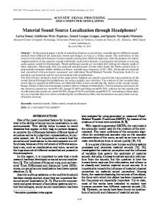
traffic from the RP is cancelled. The notation of the Shared Path Tree is (*,G). Fig. 2 describes the process of building the distributive tree for ASM technology, with the one interested receiver connected to router 2.
i-^-l2>
^
i*,G) R M Join Shaded Jitm (S,G)RMJoir!
4 Register m8S^K|« 5.
^ Source P a ^ Tme and tm^e DownStfT^ei traffic Regisfef-Slop ft^&sage
-*-• g.
^
10. .
Jl-.^ 12, X
Ji-^ 14. X
CS.G)FlMJoJn Souras Paiti Tme - SPT DownStreKafin traffic (S.G)RP-b(iPI^ Prune No iSM
mm R M Prune
HQ traffic
Fig. 2 Building the distributive tree in Any Source Multicast
3.2.
Source Path Tree
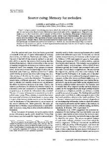
In SSM, the traffic delivery is based on (S,G) channels. If the receiver wants to receive the traffic from the specific source, it is necessary to use the multicast routing protocol enabling the SPT to be created immediately after the receiver request. This issue is solved by means of the Source Specific Protocol Independent Multicast PIMSSM using the PIM sparse-mode functionality to create an SPT between the receiver and the source without RP support. The receiver subscribes the reception from the specific (S,G) channel by means of the IGMPv3 protocol that allows defining the specific source for the multicast group. The SPT building process is shown in Figure 3.
472
PWC 2007
J..^ 2, 3. 4
•
(S.G) Sub^rxibe {S.G'^ PIM Join SfJiircB Path Tree TraJTtc flow
S - sourw (147,229.151 226) SDR - st5iirr;»'s de^J^natwd router C147.229J51.241) RDR - receiver's desig?ialed royter HP ~ RersdezvOus Pdnt nouler (147,229.151246)
Fig. 3 Building the distributive tree in Source Specific Multicast with the PIM-SSM and IGMPv3 protocol
4.
Configuration of ASM and SSM in the Experimental Network
The detailed steps of the configuration basic IP multicast are described in [2]. The basic common setting for ASM and SSM consists in enabling multicast routing on all the routers used together with the setting of the PIM-SM protocol on every interface that uses the IP multicast. The ASM with the PIM-SM requires the RP for building the Shared Path Tree. For the settings of the RP in the network the single static RP configuration was used. This way of setting is sufficient for the experimental purposes.
4.1.
Configuring ASM with a Single Static RP
It is necessary to perform the i p r p - a d d r e s s x . x . x . x [access-list] command on any router in the experimental network (x.x.x.x specifies the IP address of the RP). This access-list defines the range of the IP multicast addresses for which the RP will be used. The access-list should be assigned fi-om the 224.0.0.0 to 239.255.255.255 range with the exception of the reserved address. These reserved address for the multicast are described in [5]. For automating the RP announcement process Auto-Rendezvous Point (Auto-RP) should be used or the Bootstrap router should be used to discover and announce RP-set information for each group. For the display ofthe known RPs in the network the show i p pirn rp command is useful.
Personal Wireless Communications
4.2.
473
SSM Configuration
The configuration and management of SSM in the network are a great advantage of this technology because no RP is required for delivering traffic from the source to the multicast group. The network or rather routers need not maintain the information about active sources. The configuration of the SSM must be performed only on the routers, where the receivers are interested in the traffic reception from the specific (S,G) channel. These routers need to support two specific protocols for the SSM implementation: PIM-SSM and IGMPvS. It is necessary to check the version of the Cisco Internetwork Operating System (lOS) on the requested routers. IGMPvS is supported m Cisco lOS starting with 12.0(15)S, 12.1(8)E [6]. The current lOS version of Cisco 1800 routers used in the experimental network is 12.4(6) T3. To use SSM in the experimental network it is neecesarry to designate IP multicast address ranges which are to be used with SSM. The Internet Assigned Number Authority (lANA) has designated the IP multicast address range 232/8 [3]. There are some restrictions on the use of the IGMPvS protocol. The client application used for the traffic received from the specific (S,G) channel needs the IGMPvS protocol support m the operating system. In the Microsoft OS, the IGMPvS is supported in the Windows XP, Windows 2003 and Windows Vista versions. For the older versions (Wmdows 95, NT 4.0 SPS, 98, NT 4.0 SP4,ME a 2000) with the IGMPvl,2 support, it is possible to use the Cisco solution URL Rendezvous Directory (URD) or IGMPvS lite protocol [4]. In the UNIX OS with the kernel version starting with 2.4.22, the protocol is supported.
5.
Multicast Routing Tables
The multicast routing tables (MRT) keep and periodically update the information about the (*,G) and (S,G) states.
5.1.
ASM Multicast Routing Table
When the receiver sends the PIM-Join (IGMP record) upstream toward the RP, the record about the (*,G) state is added to MRT of the Last Hop router. If this router has no limitation in the SPT-Threshold value, the record about the (S,G) states is added immediately. Table 1 describes the record in the MRT for the 224.3.8.8 multicast group. Two entries are maintained and each of them has two timers. The literature [4] says: „Uptime indicates per interface how long in hours, minutes, and seconds the entry has been in the MRT and Expires indicates per interface how long in hours, minutes, and seconds until the entry will be removed from the multicast routing table". Expires time of the (*,G) state is stopped (never expires). The expire timer for the (S,G) state counts down from 3:00 min and it is updated every 10 seconds. The SJC flag in the (*,G) state indicates: S-Sparse mode, J - indicates that the rate of traffic flowing down the shared tree is exceeds the SPT-Threshold set for the group (default 0 kbps), C - a member of the multicast group is present on the directly connected interface [4]. The JT flag in the (S,G) state indicates: J - mentioned above.
474
PWC 2007
T ™ packets are received over the SPT. The RPF nbr abbreviation describes the IP address of the upstream router to the source [4].
Table 1. ASM multicast routing table of the Last Hop router
If the server stops sending traffic, the entry referring to the (S,G) state is deleted after 3 minutes and only the (*,G) entry is maintained as long as the receiver is requesting receipt. The entry is then updated every 60 seconds (in accordance with the IGMP Query Interval).
5.2.
SSM multicast routing table
Since in the SSM there is no mechanism to announce to a receiver that the source is not sending the traffic to the multicast group, the (S,G) state is maintained in the MRT together with the Source Path Tree from the receiver to the source as long as the receiver sends the (S,G) subscriptions. The SSM multicast routing table is described in the Table 2. If the receiver is sending the (S,G) subscription and the source is sending traffic to the multicast group, the entry in the MRT is updated every 10 seconds. If the source becomes inactive, the entry in the MRT is updated every 60 seconds. The sTI flag indicates: s - indicates that a multicast group is within the SSM range of IP address, T - indicates that packets have been received on the source path tree, I - indicates that an (S,G) entry was created by an (S,G) report [4].
Personal Wireless Communications
475
Table 2. SSM multicast routing table of the Last Hop router
6. Benefits of SSM using In the SSM, there is no problem with address allocation. If the transmission is identified from the source unicast IP address and the multicast group IP address of the 232/8 range, this final couple of addresses is unique too. It does not matter that two sources (SI and S2 e.g.) will send the traffic to one multicast group, thus for the (S1,G) and (S2,G) transmissions the network will maintain two different distributive trees. As, the transmission is identified with the unique source address, it offers more effective defense against the Denial of Service Attack (DoS). The measurement of the DoS attacks in the ASM and SSM will be performed in the future. The easy configuration and management is another benefit of the SSM too.
7.
Conclusion
In this paper are presented matters concerning the ASM and the SSM implementation in the experimental network. Using the configuration of the SSM in the experimental network, it was proved that implementation of this technology in the network where the ASM exists is easier because only the Last Hop router needs to be configured for the PIM-SSM and IGMPv3 protocols used but the IGMPv3 protocol is used only in the latter operation systems. An examination of the multicast routing tables has revealed that the SSM has no mechanism for notifying the receivers that the source
476
PWC 2007
has stopped sending the traffic to the multicast group. Thus the multicast routing table keeps the information about the (S,G) state as long as the receivers request the receipt of that channel The multicast routing tables thus keeps a lot of needless information. In ASM, the entry of the (S,G) state is deleted after 3 minutes when the source becomes inactive. The SSM is ideal for internet broadcast applications such as the audio/video transmission in real time. Customers need to get ready this technology still has not still sufficient support in the internet community. For the realization of videoconferencing and for playing online games a many-to-many delivering model is necessary that isfixllysupported by the ASM technology. Extensions to the experimental network and subsequent measurements are planned in the future. Acknowledgement This work was supported by the Grant Agency of the Czech Republic-projectNo. 102/07/1012.
References 1. Bhattacharya, S.; An Overview of Source Specific Multicast (SSM). IETF RFC 3569, 08/1989, ftp://ftp.rfc-editor.org/in-notes/rfc3569.txt 2. Cisco System, Inc.: Configuring Basic IP Multicast^ Cisco Systems, Inc., 1992-2007. www.cisco.com 3. Thaler, D. Handley, M., Estrin, D.: The Intemet Multicast Address Allocation Architecture. RFC 2908, September 2000 4. Cisco System, Inc.: Source Specific Multicast. Cisco Systems, Inc., 1992-2007. www.cisco.com 5. Cisco System, Inc. Cisco IP/TV Broadcast Server User Guide, Release 5.1. Cisco Systems, Inc., 1992-2007, www.cisco.com 6. Cisco System, Inc. IGMP Version 3. Cisco Systems, Inc., 1992-2007, wsvw.cisco.com