Experiences of Teaching Model-Driven Engineering in a Software Design Course Peter J. Clarke, Yali Wu, Andrew A. Allen
Tariq M. King
School of Computing and Information Sciences Florida International University Miami, FL 33199, USA
Department of Computer Science North Dakota State University Fargo, ND 58105, USA
{clarkep, ywu001, aalle004}@cis.fiu.edu ABSTRACT Educators continue to face major challenges in getting their students to use models effectively when developing software artifacts. As software systems become more complex it is essential that students not only learn how to create good models during software design activities but also use the models created as the blueprint for implementation. Experts in the software engineering and models communities advocate that introducing students to the concepts of Model-Driven Engineering (MDE) provide students with the insights, techniques and tools to ameliorate the difficulties associated with designing complex software systems. In this paper we describe how MDE has been integrated into the software design course at Florida International University, and present the results of a survey that was administered to the students after the class. The cornerstone of the integration has been the class project, which is based on an ongoing research project to develop a Communication Virtual Machine (CVM) technology that consists of a domain-specific modeling language, the Communication Modeling Language (CML) and a platform, CVM, that is used to model and realize communication models created using CML. The objective of the survey was to obtain empirical evidence on how MDE helps with understanding modeling concepts and the current state of the tools to support MDE. The artifacts described in this paper are available to be shared through a community-based MDD resource.
1.
INTRODUCTION
There continues to be a major demand for well-trained software engineers in industry [4]. Software engineering is still a relatively young discipline [19] requiring innovative pedagogical approaches to train new software engineers. A key component of any software engineering training program is teaching students how to use models effectively to develop software that is correct, maintainable, dependable, efficient, and usable. However, there has been little success in many
[email protected] software engineering programs on getting students to use models to support the software development process. Cowling [5] argues that the concept of modeling and software system structures are not given sufficient attention in software engineering curricula. One key area of the software development process that appears to be particularly troubling is using effective modeling techniques during software design. Software design can be classified as a wicked problem1 , which means that unlike many other engineering problems there is no: (1) immediate nor ultimate test of a solution, (2) definitive formulation of the problem, and (3) no stopping rules, among other properties. Due to the difficulty of solving the software design problem, many practitioners have given up hope that significant progress will be made from advances in programming technologies [19]. Selic [19], France and Rumpe [10] among others claim that Model-Driven Engineering (MDE) can provide software designers with the insights, techniques and tools to ameliorate the difficulty of designing software for complex systems. During the past three years a software design course has been taught at Florida International University (FIU) as an elective in the graduate program. Before students can take the class they are expected to have completed an introductory software engineering course. The design course uses MDE for teaching the major activities of software design. The motivation for using MDE is that it exposes students to the need for correct and complete models at the design stage, as several of the models will be used to generate the resulting implementation. The major project in the class has been implementing a domain-specific modeling language (DSML), and a platform to realize the corresponding domain models. The domain under consideration was modeling and realizing unified communication applications2 (e.g., conference audio/video calls, file transfer and instant messaging). In this paper we describe the MDE project given to the students in the software design class at FIU, and present the results of a survey that was administered to the students after the class. The project was based on an ongoing research project to develop a Communication Virtual Machine (CVM) technology [6] that consists of a domainspecific modeling language (DSML), the Communication Mod1 2
http://en.wikipedia.org/wiki/Wicked problem http://en.wikipedia.org/wiki/Unified communications
eling Language (CML) and a platform, CVM, that is used to model and realize communication models created using CML. The objective of the survey was to obtain empirical evidence on how MDE helps with understanding modeling concepts and the current state of the tools to support MDE.
1. Master the techniques used to develop the static models for software analysis and design using UML. 2. Master the techniques used to develop the dynamic models for software analysis and design using UML. 3. Master the techniques used to develop artifacts for software analysis and design during the software process. 4. Be familiar with the techniques used to convert a software design into an implementation using a model driven approach. 5. Be familiar with the tools and techniques used to validate the artifacts developed during the software analysis and design. 6. Be familiar with a method to plan and document the software design process for a medium-size software application.
The rest of the paper is organized as follows. Section 2 motivates why the project was used in the design course. Section 3 provides details of the course structure. Section 4 provide background on the CVM technology and describes the project objectives. Section 5 briefly describes the project deliverables for the course. Section 6 presents the results of the survey that was given to the students in the class. Section 7 presents the related work and we conclude in Section 8.
2.
MOTIVATION
Integrating MDE into the software design class was motivated by the fact that students in the software engineering classes would create software designs during the development process, and then create an implementation that did not reflect the designs. As a result, there was a need to develop a project that needed the students to use the design they created as input for some aspect of the project. The authors were part of a research project to create the CVM technology [6] and therefore decided to use aspects of the research as the class project. The objectives were as follows: (1) expose students in the class to ongoing research; (2) introduce students to a new paradigm in the software engineering and models communities, MDE; (3) provide students with a “real” project that allowed them to develop models that can be executed; (4) introduce students to a paradigm where models are “first-class citizens” both during design and at execution time; and (5) expose students to the tools available to support MDE and software design. After teaching the software design class for the first year using MDE, students got very excited and motivated when they saw how MDE could be used to create executable models that were generated from their domain-specific models. In addition, many of the students finally understood why it was important to create correct models, since during the project a class diagram was used to create the metamodel for a DSML. This artifact was then used to automatically generate a graphical modeling environment. As a result of integrating MDE into the software design class several of the students joined the CVM research project and completed independent studies. The artifacts developed by these students can be seen on the CVM project’s web page3 .
3.
COURSE DETAILS
The software design course runs for one semester, 16 weeks in length, and is taught as a lecture section consisting of one class a week for two and a quarter hours. The prerequisite of the course is a graduate course in software engineering. The main objective of the course is to conduct an in-depth study of object-oriented analysis and design of software systems based on the standard design language UML. Primary topics of study include the use-case driven approach for software analysis, system design and detailed design. The outcomes of the course are as follows: 3
http://www.cis.fiu.edu/cml/
The required textbook for the course was “Model-Driven Software Development: Technology, Engineering, Management” by Stahl and V¨ olter [21]. Additional reading material included the paper by Hailpern and Tarr [11], Graphical Modeling Framework (GMF) tutorial [9] and the UML specification [17]. The students taking the course were evaluated based on three examinations (60%) and a team project (40%) consisting of three main deliverables. Each deliverable consisted of a written document and a class presentation (20 minutes). To assist the students with the class project two PhD students working in the area of model-driven development were assigned to the class. There were five teams in the class consisting of between four and five students.
4.
PROJECT DESCRIPTION
In this section we describe the project that was assigned to the students in the software design class. The class project was based on a research project, CVM technology [6], that supports the rapid conception, construction and realization of new application-specific communication services through a model-driven approach.
4.1
CVM Technology
As previously stated, the CVM technology consists of two parts: CML, a DSML, and the platform, CVM, that is used to model and realized the communication models.
4.1.1
Communication Modeling Language
CML is a domain-specific modeling language that is being developed to model communication-intensive applications. The initial version of CML, developed by Clarke et al. [3], was based on the domain analysis of several communicationintensive scenarios from the healthcare domain. The primitive communication operations that can be modeled by CML include: (1) connection establishment, (2) data (primitive and user-defined) transfer, (3) addition/removal of participants to/from a communication, (4) dynamic creation of structured data, and (5) specification of properties associated with a particular data transfer. Two categories of communication models can be described using CML, communication schemas and communication instances. The relation between a schema and an instance
No. 1
Non-Terminal Production
Name
Name +
userSchema
local
connection
connection
mediaAttached 2
Terminal
isAttached isAttached
connection
local
4
remote
5
mediaAttached
6
device
+
remote
connection
3
connection
Person
isAttached
device
device
Person
isAttached
*
Medium
form_NT
Capability
device
Device
person
Person
medium
Medium
*
+ form
Form
Device
form 7
form
*
form
or
Medium
deviceCapability
Form
Capability
*
* indicates zero or more occurrences of the symbol. + indicates one or more occurrences of the symbol The link connecting the symbol also repeated
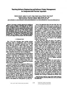
Table 1: Grammar for G-CML is similar to the relation between a class and an object in programming languages. An instance captures all information in a communication at a particular point in time and can be directly executed. On the other hand, a schema describes the possible communication configurations of a conforming instance. There are currently two equivalent variants of CML: the XML-based (X-CML) and the graphical (G-CML). Table 1 shows the graphical grammar for G-CML. Note that there is an equivalent attributed grammar for X-CML. Columns 2 and 3 of Table 1 show the non-terminal definitions of G-CML, while Columns 4 and 5 show the terminal definitions. The first row of Table 3 shows the structure of the userSchema non-terminal, which consists of the local non-terminal connected to one or more connection nonterminals (connection). To indicate that a symbol may be repeated we use the character “*” for zero or more repetitions and “+” for one or more repetitions. The right side of the first row in Table 1 shows the terminal for connection, which consists of a diamond shaped box with the label “connection”. The remaining non-terminals and terminals in Table 1 can be described in a similar manner. The at-
tributes associated with the G-CML terminals are not shown in Table 1.
4.1.2
Communication Virtual Machine
CVM [6] provides an environment that supports the modeling and realization of user-centric communication services. The high-level design of CVM is based on a four layered architecture. The main components of CVM are as follows: 1. User Communication Interface (UCI), provides a modeling environment for users to specify their communication requirements using CML. UCI currently provides the user with two interfaces: a user-friendly GUI for novice users, and a modeling environment for expert users. 2. Synthesis Engine (SE), is responsible for negotiation and the transfer of media between participants in a communication. The SE generates an executable script (communication control script) that is interpreted by the next layer in the CVM. 3. User-centric Communication Middleware (UCM), interprets the communication control script to manage
and coordinate the delivery of communication services to users. 4. Network Communication Broker (NCB), provides a network-independent API to UCM and works with the underlying networks or communication frameworks (e.g., Skype [20]) to deliver the communication services.
4.2
User/Developer (interactive)
User GUI
UCI Communication Modeling Environment
Project Description
The project given to the Software Design class was Rapid Realization of Communication Services System (RRComSSys). The project consisted of three components: (1) creation of a communication modeling environment, (2) transformation of a graphical communication model (G-CML) into a XML communication model (X-CML), and (3) synthesis of an XCML communication model into function calls to the Skype API [20] to realize a communication service.
G-CML
Model Transformation Environment
X-CML Repository
UCI-SE Interface
X-CML instance Synthesis Engine (SE) Calls to Skype API
There are two types of models that shall be developed using the modeling environment: (1) a communication schema (similar to a use case) and (2) a communication instance (similar to a scenario). The RRComSSys can only execute communication instances. That is, if a user tries to execute a communication schema the system should request that the user enters the required data to convert the schema into an instance. For example, the schema does not usually contain the recipient contact information for a call; and therefore the system should ask the user to enter the recipient’s caller ID. The detailed descriptions of the three components are as follows:
Skype API
Legend User interactions Flow of control and data Flow of data only
Communication Framework
Figure 1: High-level design for RRComSSys. 3. Validate the X-CML generated using the complete XCML schema (metamodel represented as XML). 4. The X-CML should be stored with the extension .cml.
Component 1: Communication Modeling Environment (CME) The CME shall be developed using the Eclipse Modeling Framework (EMF) and the Graphical Modeling Framework (GMF). G-CML shall be the graphical language used to specify the user’s communication requirements. The following steps shall be required to build the CME: 1. Identify several scenarios that cover the functionality for the development of a communication model. 2. Create the metamodel (i.e. class diagram and constraints) for G-CML (see Figure 1) that can be used to generate the family of communication models for the communication services required by the use cases. 3. Create a modeling tool using EMF and GMF based on the abstract syntax class diagram for G-CML. Ensure that you can save and load CML models (schemas and instances) to/from a repository of models. Component 2: Model Transformation Environment (MTE) The MTE takes as input a G-CML model and transforms it to an X-CML model. The steps in the transformation process are as follows: 1. The XML model created by the CME (that represents the G-CML) should be used to generate the X-CML. 2. Parse the XML model generated by the CME and based on the nodes and the relationships found in the model, generate the appropriate X-CML. The scenarios should provide specific examples to test the X-CML generation.
Component 3: Synthesis Engine (SE) The SE takes as input an X-CML instance and realizes a communication service. That is, it makes the appropriate calls to the Skype API. The steps for converting the X-CML to Skype API calls are as follows: 1. Parse the X-CML and build a parse tree or similar data structure. 2. Walk the parse tree or parse data structure and generate the Skype API calls based on the nodes and their relationships in the parse tree. Figure 1 shows the high-level design that should be used in the construction of the RRComSSys platform. The User GUI will be used to: (1) activate either the CME or the MTE located in the user communication interface (UCI); save and load G-CML/X-CML models to/from the repository; and (3) execute instances of X-CML models. The user/developer interacts with the CME during the construction of the GCML models.
5.
PROJECT DELIVERABLES
In this section we briefly describe the artifacts created by one of the project teams in the class. The students were expected to submit three deliverables: (1) The Software Requirements Document (SRD) containing communication scenarios and uses cases elicited from one of three domains (healthcare, disaster management and scientific collaboration), and the
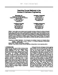
Figure 2: Screen shot of the communication modeling environment. artifacts for requirements analysis (object diagrams and sequence diagrams). The scenarios focused on modeling communication applications using G-CML and the realization of the G-CML models using the RRComSSys platform. (2) The Design Document (DD) containing the metamodel for the G-CML, the architectural design of the RRComSSys, the generative architecture showing the model transformations, a detailed design containing class diagrams, state charts and sequence diagrams. (3) The Final Document containing the SRD, DD, the results of testing the system against the requirements and a user’s guide. Due to the space limitations of the paper we cannot show all of the artifacts created during the project. However, the following paragraph summarizes a scenario created by the members of a project team working in the area of healthcare. Scenario: After heart surgery Dr. Monteiro (the cardiologist) contacts Dr. Sanchez (family doctor) and Dr. Lopez (a heart specialist) to update them on a patient’s condition. During communication with doctors Dr. Sanchez and Dr. Lopez, Dr. Monteiro sends them the post-surgery echocardiagram (echo) of the patient’s heart and a text summary of the patient’s current condition. Figure 2 shows the G-CML model that was created in the communication modeling environment for the scenario. The model represents a communication schema. The details for Dr. Monteiro are shown to the left of the model in Figure
2. During the execution of the model by the RRComSSys the user (Dr. Monteiro) is required to enter the contact information for Dr. Sanchez and Dr. Lopez thereby creating a communication instance. Note that this instance may be saved in a model repository and executed again at a later date. The project required the students to develop a class diagram to represent the G-CML syntax shown in Table 1. The class diagram was then modified so that it could be used as input to GMF to generate the modeling environment. The XML schema for X-CML was provided to the students. The students were also required to develop a model transformation that converted the G-CML model shown in Figure 2 to its X-CML equivalent. This involved developing a model transformation that takes as input the XML representation of G-CML from the GMF environment and converting it to the X-CML representation, as specified by Deng et al. [6].
6.
CASE STUDY
In this section we describe the format of the survey questionnaire and the results obtained after administering the survey to the students at the end of the software design class.
6.1
Survey
To determine the impact of using MDE in the software design class, we administered a survey to the students in the class. There were twenty-four (24) students in the class of which twenty-three (23) took the survey. The thirteen of
the survey questions are shown in Table 2 and the remaining four are shown in Appendix A. questionnaire administered to the students is shown in Appendix A. The questionnaire is divided into three main sections, these are: (1) Modeling Concepts, (2) Tool Support, and (3) Other Questions. Three types of questions were used in the questionnaire: questions with responses Yes or No; questions with responses that map to the Likert scale 4 1 - Strongly Disagree, 2 - Disagree, 3 - Undecided, 4 - Agree, 5 - Strongly Agree; and open ended questions. The section on Modeling Concepts focused on how using MDE supports the need for, and the importance of, using good software designs during software development. Unlike the traditional approach to software development, several of the software designs created in the project, described in Section 4.2, are used as input to the tools used in the project. For example, when creating the visual editor in the communication modeling environment (CME), using the Eclipse Modeling Framework [8], the input is the metamodel for GCML represented as a ECore [8] class diagram. Tool Support was the second section in the survey questionnaire and it focused on the usefulness of the tools available to support software design. Many educators comment on the lack of tool support for the various software design and MDE activities. We felt that getting the students perspective on this issue was relevant to the study. The final section of the questionnaire addressed several other issues that were deemed important to the study, such as the students’ experience in industry, the use of UML in industry, and the importance of having an MDE repository of software artifacts.
6.2
Results
The results for the questions in the survey that were not open ended are shown in Table 2. These results are for questions 1 through 9, 11, and 15 through 17. Table 2 consists of three columns labeled: No. for the question number, Question the actual question, and Results the tabulated results. In the results column the value of the scale is shown in italics and the corresponding tabulated value is shown in parentheses following the scale value. For example, in the row representing question (1.), there are three (3) students who answered Yes and 20 answered No. In the row labeled (2.) one (1) student answered 1 - Strongly Disagree, zero (0) answered 2 - Disagree, seven (7) answered 3 - Undecided, twelve (12) answered 4 - Agree and three (3) answered 5 Strongly Agree. Table 2 is divided into three sections corresponding to the sections of the questionnaire in Appendix A. The results obtained in the Modeling Concepts section of the questionnaire revealed that only 13% of the students had any experience using MDE before the class. A majority of the students, 70%, felt that MDE helped them with their understanding of software design, while over 90% of the students thought that MDE highlighted the importance of creating correct models. With respect to understanding the modeling language used to create software models, 87% and 69% of the 4
http://en.wikipedia.org/wiki/Likert scale
students felt that using MDE encourages software designers to understand the syntax and semantics of the modeling language, respectively. A majority of the students, 87% felt that using MDE helped them understand how abstraction can be used to create complex software models. Questions 7 and 8 in the questionnaire were targeted more towards MDE: 78% of the students felt that MDE empahsizes the problems associated with automatic code generation, while 91% thought that MDE shows how domain-specific modeling languages may be used to rapidly develop software applications. The Tool Support section results support many of the claims educators have been making for a number of years. A majority, 96%, of the class had never created a graphical modeling environement before. A slight majority of the students, 56%, thought that the Eclipse Modeling Framework (EMF) was difficult to use. There were several reasons why the students thought EMF was difficult to use. These included: (a) documentation was not helpful; (b) a better tutorial to explain steps required to create the modeling tool; (c) more examples are needed; (d) error descriptions not very helpful; and (e) a more user-friendly interface is needed. Several UML tools were used for the project including: StarUML [22]; Eclipse UML 2.0 plugin [7]; MS Visio [15]; IBM Rational Rose [12]; IBM Enterprise Architect [13]; and Altova Umodel [1]. The students stated the following reasons for selecting a particular UML tool: StarUML - easy to use, more UML diagrams available; Eclipse UML 2.0 Plugin provides the ability to use UML profiles; IBM Rational Rose - easy to use; IBM Enterprise Architect - very user-friendly interface. In the Other Questions section just over half, 52%, of the students worked in the software development industry. Of the students that work in the software industry the majority did not use UML in their job. All the students in the class, 100%, thought that a repository of MDE artifacts would help them gain a better understanding of MDE.
6.3
Discussion
The results presented in this section is an indirect measure of the students’ knowledge and attitude toward MDE after taking the software design class. Although there are other techniques that can be used to perform more direct measures, the study provided us with information that can be used to improve future editions of the course. One area of major concern is the availability of adequate tools to support pedagogy in software design. Several UML diagrams were used in the course to develop the design artifacts for the project. In addition, the students were also required to create UML profiles to assist in modeling concepts from the communication domain. In the previous section the UML tools used by various students in the class were identified. Although several tools were identified student teams used at most two tools on the project, one for developing the UML profiles e.g., Eclipse UML 2.0 plugin, and one for creating diagrams not supported by the Eclipse environment, e.g., StarUML. The ideal UML tool should provide the students with the ability to create UML diagrams, perform a check of the model based on the syntax
No. Question Modeling Concepts: 1. Have you ever used MDE before this class? 2. MDE helps with your understanding of software design. 3. MDE highlights the importance of creating correct models during software development. 4. MDE encourages designers to understand the syntax of the modeling language. 5. MDE encourages designers to understand the semantics of the modeling language. 6. MDE helps with understanding how abstraction supports the creation of models for complex software products. 7. MDE emphasizes the problems associated with automatic code generation from models. 8. MDE shows how domain-specific modeling languages may be used to rapidly develop software applications. Tool Support: 9. Have you ever created a graphical modeling environment before taking this class? 11. The Eclipse Modeling Framework (EMF) was easy to use. Other Questions: 15. Are you currently working in the software development industry? 16. Do you use UML in your current job? 17. Do you think a repository of MDE educational artifacts (e.g. sample project) would help you gain a better understanding of MDE?
Results Yes (3) No (20) 1 (1) 2 (0) 3 (7) 4 (12) 5 (3) 1 (0) 2 (0) 3 (2) 4 (13) 5 (8) 1 (0) 2 (1) 3 (2) 4 (14) 5 (6) 1 (0) 2 (0) 3 (7) 4 (9) 5 (7) 1 (0) 2 (0) 3 (3) 4 (18) 5 (2) 1 (0) 2 (1) 3 (4) 4 (10) 5 (8) 1 (0) 2 (0) 3 (2) 4 (13) 5 (8)
Yes (1) No (22) 1 (4) 2 (9) 3 (5) 4 (3) 5 (2) Yes (12) No (11) Yes (5) No (18) Yes (23) No (0)
Table 2: Partial results of the survey given to the students of the Software Design Class. and semantics of UML, and enforce the constraints defined by the UML profiles. The students’ lack of experience in developing a graphical modeling environment was a major challenge. This challenge was exacerbated in part by the lack of adequate documentation for developing the graphical environment using GMF/EMF. Only a slight majority of the students found the EMF framework difficult to use, however this was after spending many hours to create the modeling environment. It should also be pointed out that if the students were unable to generate the modeling environment then they would have received a low grade in the class project.
7.
RELATED WORK
In the Educators Symposium of the MODELS conference in 2008 [14], three thematic groups of paper submissions were discussed, including teaching model semantics, tool support for teaching models and modeling course concepts. The courses or teaching methods reported focused on one aspect of the modeling process: either tooling support or semantic specification. The course described in this paper incorporates various phases of a complete MDE process. Students first have to construct a domain-specific modeling environment using EMF/GML tooling support, and then define model transformation and synthesis, which provides semantics to a user defined model. The idea of adopting a phased development approach to teaching model-based software engineering is not new in education practices [16]. However, in our approach, all the education artifacts and deliverables are centered on the manipulation of models, including a metamodel design, model
transformation design, and so on. As models designed in earlier steps are directly used in subsequent phases, it is expected that students could experience by themselves how earlier modeling errors could significantly affect later development activities. Our course also shares some similar traits with courses on teaching domain-specific modeling. Pareto in [18] proposed a course in which educators give students two existing domainspecific languages and an existing Robotics platform and ask students to implement one of the DSLs on the platform, using the Microsoft DSL toolkit. While Pareto focused on the definition of graphical domain-specific languages, and the translations from graphical languages to embedded target platforms, the course described in this paper aims at a more comprehensive outcome, covering techniques for creating domain specific modeling environment and transformations between models of different representations. Gokhale and Gray [2] describe their experiences in developing and an teaching MDE course. The authors utilized their research in MDE to develop and teach courses for graduate and undergraduate students. These hands on courses centered on the enhancement and use of their CoSMIC and C-SAW tools. While GMF / EMF were the tools of choice in our course, our approach focused more on the methodologies of MDE.
8.
CONCLUSION
The adequate use of modeling by software engineering students continue to be a major challenge for many software engineering educators. To tackle this problem Model-Driven Engineering (MDE) was integrated into a software design
course at Florida International University. The quality of the artifacts produced during the class project and the results of a survey administered to the students after the course showed that MDE has a positive impact on helping students to better understand how models can be used during software design.
9.
ACKNOWLEDGMENTS
This work was supported in part by the National Science Foundation under grant HRD-0833093. We would like to thank Barbara Espinoza for her assistance in preparing and administering the student survey. The authors would also like to thank the reviewers for their suggestions on how to improve the paper.
10.
[14]
[15]
[16]
REFERENCES
[1] Altova. UModel. http: //www.altova.com/products/umodel/uml_tool.html (Jun. 2009). [2] Anirudha S. Gokhale and Jeff Gray. Advancing model driven development education via collaborative research. In Proceedings of the Educators Symposium at the 8th International Conference, MoDELS 2005, Oct. 2005. http://models05-edu.upb.de/proceedings/ models05-edu-proceedings-letter.pdf (Jun. 2009). [3] P. J. Clarke, V. Hristidis, Y. Wang, N. Prabakar, and Y. Deng. A declarative approach for specifying user-centric communication. In CTS, pages 89 – 98. IEEE, May 2006. [4] CNN. Best jobs in america. http://money.cnn.com/magazines/moneymag/ bestjobs/2006/top50/index.html (Jun. 2009). [5] A. J. Cowling. Modelling: A neglected feature in the software engineering curriculum. In CSEET ’03: Proceedings of the 16th Conference on Software Engineering Education and Training, page 206, Washington, DC, USA, 2003. IEEE Computer Society. [6] Y. Deng, S. M. Sadjadi, P. J. Clarke, V. Hristidis, R. Rangaswami, and Y. Wang. CVM - a communication virtual machine. JSS, 81(10):1640–1662, 2008. [7] Eclipse . Uml2. http: //www.eclipse.org/modeling/mdt/?project=uml2 (Jun. 2009). [8] Eclipse Foundation. Eclipse modeling framework. http://www.eclipse.org/modeling/emf/ (Jan. 2009). [9] Eclipse Foundation. Gmf tutorial, Jan. 2009. http://wiki.eclipse.org/GMF_Tutorial. [10] R. France and B. Rumpe. Model-driven development of complex software: A research roadmap. In FOSE ’07: 2007 Future of Software Engineering, pages 37–54, Washington, DC, USA, 2007. IEEE Computer Society. [11] B. Hailpern and P. L. Tarr. Model-driven development: The good, the bad, and the ugly. IBM Systems Journal, 45(3):451–462, 2006. [12] IBM Corporation. Rational Rose. http://www-01. ibm.com/software/awdtools/developer/rose/ (Jun. 2009). [13] IBM Corporation. Rational Software Architect Standard Edition. http://www.ibm.com/
[17]
[18]
[19] [20] [21]
[22]
developerworks/rational/products/rsase/ (Jun. 2009). Michal Smialek (Ed.). Promoting software modeling through active education. In Proceedings of the Educators Symposium at the 11th International Conference, MODELS 2008, Sept. 2008. http://www. iem.pw.edu.pl/edusymp08/EduSympProcAbs.pdf (Jun. 2009). Microsoft Corporation. MS Visio. http://office. microsoft.com/en-us/visio/default.aspx (Jun. 2009). Miroslaw Staron (Ed.). Educators symposium. In Proceedings of the 3rd Educators Symposium at the 10th International Conference, MoDELS 2007, Oct. 2007. http://models2007.isis.vanderbilt.edu/ edusymp-proceedings-a4.pdf (Jun. 2009). OMG. Omg unified modeling language (omg uml), superstructure, v2.1.2, Nov. 2007. http://www.omg.org/spec/UML/2.1.2/. L. Pareto. Teaching Domain Specific Modeling. In Proceedings of the 3rd Educators Symposium at the 10th International Conference, MODELS 2007, Oct. 2007. http://models2007.isis.vanderbilt.edu/ edusymp-proceedings-a4.pdf (Jun. 2009). B. Selic. The pragmatics of model-driven development. IEEE Softw., 20(5):19–25, 2003. Skype Limited. Skype developer zone, Feb. 2007. https://developer.skype.com/. T. Stahl, M. V¨ olter, J. Bettin, A. Haase, S. Helsen, and K. Czarnecki. Model-Driven Software Development: Technology, Engineering, Management. John Wiley & Sons, first edition, 2006. StarUML. Staruml - the open source uml/mda platform. http://staruml.sourceforge.net/en/ (Jun. 2009).
APPENDIX A. SURVEY Model Driven Engineering (MDE) Questionnaire Please complete the following questionnaire to evaluate the contents of the course with respect to the use of model driven engineering in a software design course. You may write additional comments in the space provided. Please use the following scale: 1 - Strongly Disagree; 2 - Disagree; 3 - Undecided; 4 - Agree; 5 - Strongly Agree. Please circle your choice. Questions 1 - 9, 11, 15 - 17 are shown in Table 2. Tool Support: 10. If you answered Yes to (9) list the tools you have used: 12. If your answer to (11) was four or less, state how EMF may be improved: 13. List the UML tools you used for the project: 14. Which of the tools listed in (13) was most useful and state why: Other comments related to Tool Support: Other Comments related to MDE: