ISIJ International, Vol. 56 (2016), ISIJ International, No. 4 Vol. 56 (2016), No. 4, pp. 647–653
Experimental and Numerical Investigation of Trailing Heat Sink Effect on Weld Residual Stress and Distortion of Austenitic Stainless Steel Shigetaka OKANO* and Masahito MOCHIZUKI Graduate School of Engineering, Osaka University, 2-1 Yamada-oka, Suita, Osaka, 565-0871 Japan. (Received on November 14, 2015; accepted on December 10, 2015)
In this study, welding with a trailing heat sink was applied to austenitic stainless steel for reducing the weld residual stress and distortion. The effects on temperature profiles, residual stress and distortion were experimentally investigated through the use of gas tungsten arc welding with and without a water-cooling device. As the results, the weld residual stress and distortion can be reduced without affecting the weld penetration by welding with a trailing heat sink. Numerical investigation was also performed using the three-dimensional thermal elastic-plastic finite element analysis. A numerical model of gas tungsten arc welding was constructed based on the physics of the welding arc. The calculated weld penetration, temperature profiles, residual stress and distortion were in good agreement with those measured under the same welding conditions. Using the simplified model of homogeneously distributed heat sink on the basis of the developed welding simulation, the effect of intensity of the heat sink on the weld residual stress and distortion was quantified. Furthermore, the mechanism of the reduction of weld residual stress and distortion was discussed based on the temperature distribution variation in welding with a trailing heat sink. Based on the results, the effectiveness of welding with a trailing heat sink in reducing the weld residual stress and distortion of austenitic stainless steel has been clarified. KEY WORDS: weld residual stress; weld distortion; welding with a trailing heat sink; water cooling; austenitic stainless steel.
1.
buckling distortion, generates larger than other structural steels because the thermal expansion coefficient of the material is larger. Then, controlling the weld residual stress and distortion is likely to become more important technical issues in the austenitic stainless steel. Arc welding process is now commonly-used among the various welding processes but provides excessive heat input to join two pieces of materials. Naturally, lower heat input welding is more preferable in reducing weld residual stress and distortion. However, lower heat input welding is in actually limited in obtaining sufficient weld penetration. Then, another approaches become more attractive from different perspectives of small and large in weld heat input. Welding with a trailing heat sink is one of the in-process control methods that reduce weld residual stress and distortion. In related work, a dynamic controlled low-stress non-distortion (DC-LSND) welding process3) was proposed as an active in-process buckling control method for steel sheets. Further studies on mechanism elucidation numerically showed that longitudinal thermal tensioning was realized due to a saddle-shaped temperature field behind the weld pool and reduce the compressive plastic strain that developed during welding.4,5) Meanwhile, this method was applied to various materials6,7) and welding processes.8,9) In recent years, the effectiveness of welding with a trailing heat sink in reducing the rotational deformation dur-
Introduction
Welding has long been recognized as an essential technology in the fabrication process of various objects such as ships, bridges, construction machines, power plants, and automobiles. However, the welding process generally produces residual stress and distortion. Weld residual stress influences the brittle fracture, fatigue and stress corrosion cracking in the welded structure. Weld distortion also deteriorates the dimensions and performances of structures and influences the appearance of the finished products. Then, the weld residual stress and distortion are typically controlled by the mechanical and thermal techniques, which involve costly processing in addition to the welding process. However, in-process control methods to reduce weld residual stress and distortion are more preferable than pre- and postwelding countermeasures when improving manufacturing efficiency. It is well known that the weld residual stress and distortion are influenced by various factors of material properties, weld heat input conditions and structural stiffness.1,2) In austenitic stainless steel, longitudinal tensile stress covers a lot of territory on welds and various deformations, including * Corresponding author: E-mail:
[email protected] DOI: http://dx.doi.org/10.2355/isijinternational.ISIJINT-2015-659
647
© 2016 ISIJ
ISIJ International, Vol. 56 (2016), No. 4 Table 1.
Chemical compositions and mechanical properties of SUS316L used.
Chemical composition (mass%)
Mechanical properties
C
Si
Mn
P
S
Ni
Cr
Mo
Fe
0.2% proof stress (MPa)
Tensile stress (MPa)
Elongation (%)
0.014
0.69
1.09
0.032
0.005
12.13
17.42
2.06
Bal.
260
538
58
ing butt welding10) or angular distortion generated due to temperature gradient in the thickness11) was also reported. Thus, welding with a trailing heat sink has the potential to be a useful technique for reducing the weld residual stress and distortions in various materials and welding processes. Continued studies are demanded to extend the range of application of this method. In this study, welding with a trailing heat sink was applied to austenitic stainless steel for reducing the weld residual stress and distortion. The effects on temperature profiles, residual stress and distortion were experimentally investigated through the use of gas tungsten arc welding with and without a water-cooling device. After that, numerical investigation was also performed by using a model of gas tungsten arc welding with or without a trailing homogeneously distributed heat sink. Through these investigations, the effectiveness of welding with a trailing heat sink in reducing the weld residual stress and distortion and its mechanism are discussed. 2.
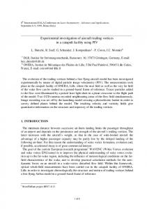
Fig. 1. Configuration of the specimen to be welded.
(a)
Experimental Investigation
2.1. Testing Material and Welding Procedure Low carbon austenitic stainless steel, JIS SUS316L, was used as testing material in the experiment. The chemical composition and mechanical properties of the material are shown in Table 1. Figure 1 shows configuration of the specimen to be welded. The dimensions of the specimen were 300 mm in length, 300 mm in width and 6 mm in thickness. The weld length was 280 mm, which left unwelded sections of 10 mm at both ends of the specimen. Bead-on-plate welding was implemented by using gas tungsten arc welding process with or without a trailing heat sink. The welding conditions were a 200 A welding current, a welding speed of 4 mm/s and a 3 mm arc length. The shielding gas was 100% Ar, and the flow rate was 3.33 × 105 mm3/s. A trailing heat sink was realized using a water-cooling device, as shown in Fig. 2. This device consisted of a water tube with a bottom of sponge, which was water soaked and brought into contact with the surface of the specimen to be welded. The dimensions of the sponge, which approximately corresponds to the cooling area, were 50 mm in length and 65 mm in width. The water-cooling device was attached to the TIG weld torch with a following distance of 35 mm, and ordinary tap water was used for cooling. The water flow rate was 3.8 × 104 mm3/s. The specimen to be welded was placed on a sill plate because of the heat transfer from the bottom of the specimen to the air. No restraints were used for preventing thermal deformation due to welding.
(b)
Fig. 2. Appearance of TIG weld torch with water-cooling device. (a) Schematic illustration, (b) Photograph.
by thermocouples located around the weld line at the center of the welded specimen, as shown in Fig. 3. Weld longitudinal bending and angular distortions were estimated respectively based on the deflection of the specimen after welding, as shown in Fig. 4. The deflections of the specimen were measured by displacement gauges on the weld line and both sides of the weld line at the center of the welded specimen. The weld residual stresses were measured by X-ray stress measurement using 2θ-sin2ψ method.12) The conditions of X-ray stress measurement are shown in Table 2. The X-ray irradiation was limited to a defined area of 4 × 4 mm2 by masking. The measurement locations are shown in Fig. 5 and longitudinal residual stress is focused in the measurement experiment. Dimensions of the weld penetration were
2.2. Measuring Objects and Methods The temperature profiles during welding were measured © 2016 ISIJ
648
ISIJ International, Vol. 56 (2016), No. 4 Table 2.
X-ray stress measurement conditions.
Apparatus
AutoMATE (Rigaku)
Wave length (nm)
0.2087 (CrKβ)
Power (kV, mA)
40, 40
Irradiated area (mm × mm)
4×4
Diffraction plane [γ Fe]
{311} (2θ0 =148.52 deg)
Measuring frame
10 frame/measuring point
Measuring time (s)
1 h/frame
Oscillation angle (°)
±5
Stress constant
−366 MPa/deg
Fig. 3. Procedure for measuring temperature profiles on welds.
Fig. 5. Procedure for measuring longitudinal residual stress by X-ray diffraction method.
Fig. 6. Trailing heat sink effect on temperature profiles on welds. Fig. 4. Procedure for measuring deflections and estimating longitudinal bending and angular distortions.
the highest temperature decreases at the measurement point from B to D, except A. It was then confirmed that the water provided to the surface of the material was almost-totally boiled not to remain after welding. As can be seen from temperature profiles at measurement point A, the temperature distribution near the weld pool is little influenced by a trailing heat sink. It has thus been concluded that the temperature distribution around the heat affected zone except near the weld penetration can be controlled by a trailing heat sink using the water-cooling device. As the result, it is
also measured from the observation of macroscopic crosssection of the welded specimens. 2.3. Results and Discussion Figure 6 shows the comparison of temperature profiles during welding between with and without a trailing heat sink. At all measurement points, the temperature during welding is cooled more rapidly by a trailing heat sink and 649
© 2016 ISIJ
ISIJ International, Vol. 56 (2016), No. 4
expected to mitigate thermal stress and then reduce plastic strain to be developed due to welding. Figure 7 shows the comparison of weld distortions after welding between with and without a trailing heat sink. The longitudinal bending and angular distortions can be reduced by approximately 50% and 65% respectively by a trailing heat sink. Meanwhile, Fig. 8 shows the comparison of distribution of weld longitudinal residual stress between with and without a trailing heat sink. The value of high tensile stress around weld line is little influenced but the width in tensile stress region becomes smaller by a trailing heat sink. It has thus been experimentally confirmed that the weld residual stress and distortion can be reduced by a trailing heat sink. 3.
properties of the low carbon austenitic stainless steel were used with consideration for temperature dependencies, as shown in Figs. 10(a) and 10(b), respectively in the thermal conduction and thermal elastic-plastic analyses. Also, the work hardening of the material was taken into account in the thermal elastic-plastic analysis, as shown in Fig. 10(c). As
Numerical Investigation
3.1. Finite Element Model Numerical investigation was also performed using the three-dimensional thermal elastic-plastic finite element analysis. In the numerical analysis, a finite element analysis code, ABAQUS ver. 6.9, was used. The finite element model used was a bead on plate model of a low carbon austenitic stainless steel. The model was symmetrical to the weld line, as shown in Fig. 9. The dimensions of plate are the same as used in the experiment and fine mesh of 2.5 mmx × 2.5 mmy × 1.5 mmz was used around the weld line. The commonly-used thermo-physical and mechanical
Fig. 9. Finite element model used in numerical analysis. (a)
(b)
Fig. 7. Trailing heat sink effect on weld distortions. (c)
Fig. 10.
Fig. 8. Trailing heat sink effect on distribution of weld longitudinal residual stress.
© 2016 ISIJ
650
Material properties of SUS316L used in numerical analysis. (a) Thermo-physical properties, (b) Mechanical properties, (c) Work hardening behavior.
ISIJ International, Vol. 56 (2016), No. 4
boundary condition in the thermal conduction analysis, the heat transfer and thermal emission from the surface of material to the air were considered. The heat transfer coefficient was set to 11.0 × 10 − 6 W/mm2K and the thermal emissivity was set to 0.5. No restraints were considered for preventing thermal deformation due to welding in the thermal elasticplastic analysis. The welding heat source model of gas tungsten arc welding was developed based on the physics of the welding arc13) as two-dimensional heat flux provided on the welded surface. The distribution of heat input is defined in the following equation.
{
} (
agreement with those measured. The effectiveness of heat source modeling in gas tungsten arc welding has thus been experimentally validated.
(a)
)
w ( x, y,t ) = (q / π R 2 )exp − ( x − vt ) / R 2 exp − y 2 / R 2 ..... (1) 2
(b)
where q is welding heat input per unit time, R is the radius of the Gaussian distribution, v is welding speed, and t is time. The welding heat input q and radius of Gaussian distribution R can be determined depending on the welding conditions. The weld heat input q and radius of Gaussian distribution R were set to 1 980 J/s and 3.3 mm respectively on the supposition that the welding current is 200 A and arc length is 3 mm in tungsten inert gas welding using 100% Ar shielding gas. For a trailing heat sink, the virtual model of homogeneously distributed heat sink was characterized as the change of the heat transfer coefficient on the surface behind the welding heat source. In the simplified model, the cooled area conforms to the dimensions of the sponge used in the experiment and the heat transfer coefficient was set to 78.125, 156.25, 312.5, 625, 1 250 and 2 500 × 10 − 6 W/mm2K, respectively, with consideration for the heat transfer from the surface of material to the flowing or boiling water.14) The longitudinal bending and angular distortions, which were similarly defined in the measurement experiment, and distribution of weld longitudinal residual stress were evaluated respectively at the center along the length of the welded plate.
Fig. 11.
Comparison between Calculation and Measurement Results Figures 11(a) and 11(b) show the comparisons of weld penetration and temperature profiles respectively between calculation and measurement. Although there are some differences, the calculated and measured weld penetration and temperature profiles are in good agreement. Figure 12 shows the comparison of weld distortions, such as longitudinal bending and angular distortions, between calculation and measurement. Both calculated longitudinal bending and angular distortions show good agreement with those measured. Figure 13 shows the comparison of distribution of weld longitudinal residual stress between calculation and measurement. Some differences can be seen in the base metal, which is approximately 100 mm away from the weld line. The existence of initial stress before welding is probable cause of the differences. Thus, minor differences can be seen between calculation and measurement but the calculated values of weld penetration, temperature profiles, longitudinal bending and angular distortions, and distribution of weld longitudinal residual stress provided good
Comparison of weld penetration and temperature profiles between calculation and measurement. (a) Weld penetration, (b) Temperature profiles.
3.2.
Fig. 12. Comparison of weld distortions between calculation and measurement.
Fig. 13. Comparison of distribution of weld longitudinal residual stress between calculation and measurement.
651
© 2016 ISIJ
ISIJ International, Vol. 56 (2016), No. 4
3.3.
Trailing Heat Sink Effect on Weld Residual Stress and Distortion Trailing heat sink effect on the weld residual stress and distortion was numerically investigated using the simplified model of homogeneously distributed heat sink. On the basis of the calculated temperature profiles in welding with a trailing heat sink at different levels of the heat transfer coefficient, weld residual stress and distortion were numerically analyzed. The effect of intensity of the heat sink on the weld distortions was quantified, as shown in Fig. 14(a). Both longitudinal bending and angular distortions (w and δ respectively) are influenced by the intensity of the heat sink and monotonically decrease with increasing the intensity of the heat sink. Meanwhile, the effect of intensity of the heat sink on the distribution of weld longitudinal residual stress was quantified. The relations between the intensity of the heat sink and feature points in the distribution of weld longitudinal residual stress were arranged, as shown in Fig. 14(b). High tensile stress at the center of the weld line, σc, is little influenced by the heat sink. In contrast, the width in tensile stress region, yp, is influenced by the heat sink and monotonically decreases with increasing the intensity of the heat sink. It has thus been concluded that both weld distortions and width in tensile stress region in longitudinal residual stress distribution monotonically decreases with increasing the intensity of the heat sink. The mechanism of the reduction of weld residual stress and distortion is discussed based on the temperature distribution variation in welding with a trailing heat sink. Figure
15(a) shows the effect of intensity of the heat sink on the temperature profiles at point A, which is already defined in Fig. 3. In the cooling process, the rapid fall in temperature occurs at a time when a trailing heat sink reaches. The fall in temperature becomes larger with the increase in the heat transfer coefficient of the heat sink. As the results, the highest temperature becomes smaller at the base metal away from the weld line, for example, evaluation points D and E, as shown in Fig. 15(b). In contrast, the highest temperature near the weld center is little influenced by the heat sink. It had already been reported that angular distortion can be reduced by welding with a trailing heat sink because the generation behavior of plastic strain was changed due to the inverse temperature gradient from the surface to the inside of the material in the cooling process during welding.15) Meanwhile, it can be considered that the reduction of longitudinal bending distortion and width in tensile stress region in weld longitudinal residual stress distribution are dependent on the degree of narrowing of the highest temperature distribution because the highest temperature distribution determines the generation area of longitudinal plastic strain to be developed in thermo-mechanical process during welding.16) Based on the comparison between calculated and measured values of weld residual stress and distortion, the intensity of the heat sink using the water-cooling device approximately corresponds to a heat transfer coefficient of 500 × 10 − 6 W/mm2K in the simplified model of the heat sink constructed for numerical analysis. In this regard, however, the calculated rapid fall in temperature due to the heat sink
(a)
(a)
(b)
Fig. 14.
(b)
Fig. 15.
Effect of intensity of heat sink on weld residual stress and distortion. (a) Weld distortion, (b) Weld residual stress.
© 2016 ISIJ
652
Effect of intensity of heat sink on temperature distribution. (a) Temperature profile, (b) Highest temperature.
ISIJ International, Vol. 56 (2016), No. 4
is obviously smaller than that actually observed in Fig. 6. The difference can be attributed to the simplified model of homogeneously distributed heat sink constructed. It can also be considered that the reduction of weld residual stress and distortions obtained in this study is mainly due to the decrease in highest temperature determines plastic shrinkage rather than the local inverse temperature gradient from the surface to the inside of the material. When the more effective heat sink can be achieved by using higher flow rate of water or other cooling medium with higher cooling capacity, it can also be expected that weld residual stress and distortion are reduced more effectively. It has thus been concluded that welding with a trailing heat sink has a potential to be a useful technique for effectively reducing weld residual stress and distortion of austenitic stainless steel without significant loss of manufacturing efficiency. 4.
structed by considering the physics of the welding arc, the calculated weld penetration, temperature profiles, residual stress and distortion showed good agreement with those measured under the same welding conditions. (3) The effect of intensity of the heat sink on weld residual stress and distortion was numerically investigated by using the simplified model of homogeneously distributed heat sink. It has been clarified that high tensile stress around weld line is little influenced by the heat sink but the width in tensile stress region, longitudinal bending and angular distortions monotonically decrease with increasing the intensity of the heat sink. REFERENCES 1) 2) 3) 4) 5)
Conclusions
6)
In this study, welding with a trailing heat sink was applied to austenitic stainless steel through the use of water-cooling device. And then, the effectiveness of welding with a trailing heat sink in reducing the weld residual stress and distortion was experimentally and numerically discussed; consequently, the following conclusions have been obtained. (1) In welding with a trailing heat sink through the use of water-cooling device, it was experimentally validated that weld residual stress and distortion can be reduced. The width in longitudinal tensile stress region, longitudinal bending and angular distortions are approximately reduced by 70, 50 and 65%, respectively. Meanwhile, high tensile stress around weld line is little influenced by the heat sink. (2) On the basis of gas tungsten arc welding model con-
7) 8) 9) 10) 11) 12) 13) 14) 15) 16)
653
K. Satoh and T. Terasaki: J. Jpn. Weld. Soc., 52 (1976), 150. K. Satoh and T. Terasaki: J. Jpn. Weld. Soc., 52 (1976), 302. Q. Guan, C. X. Zhang and C. Q. Li: Weld. World, 33 (1994), 308. P. Michaleris and X. Sun: Weld. J., 76 (1997), 451. J. Li, Q. Guan, Y. W. Shi, D. L. Guo, Y. X. Du and Y. C. Sun: J. Mater. Process. Technol., 147 (2004), 328. J. Li, Q. Guan, Y. W. Shi and D. L. Guo: Sci. Technol. Weld. Join., 9 (2004), 451. F. A. Soul and Y. H. Zhang: Sci. Technol. Weld. Join., 11 (2006), 688. J. Gabzdyl, A. Johnson, S. Williams and D. Price: Proc. SPIE, 1st Int. Symp. on High-Power Laser Macroprocessing, Vol. 4831, Bellingham, WA, (2003), 269. W. T. Han, F. R. Wan, G. Li, C. L. Dong and J. H. Tong: Sci. Technol. Weld. Join., 16 (2011), 453. M. Mochizuki, H. Yamasaki, S. Okano and M. Toyoda: Weld. World, 50 (2006), 46. S. Okano, M. Mochizuki, M. Toyoda and T. Ueyama: Sci. Technol. Weld. Join., 17 (2012), 264. A. L. Christensen and E. S. Rowland: Trans. Am. Soc. Met., 45 (1953), 638. S. Okano, M. Tanaka and M. Mochizuki: Sci. Technol. Weld. Join., 16 (2011), 209. Y. Katto: Den-Netsu-Gai-Ron, Yokendo, Tokyo, (1964), 23. S. Okano, M. Mochizuki and M. Toyoda: Q. J. Jpn. Weld. Soc., 28 (2010), 72. K. Satoh and T. Ohnishi: J. Jpn. Weld. Soc., 38 (1969), 359.
© 2016 ISIJ