www.nature.com/scientificreports
OPEN
Experimental Array for Generating Dual Circularly-Polarized DualMode OAM Radio Beams
received: 10 October 2016
Xu-Dong Bai1,2, Xian-Ling Liang1, Yun-Tao Sun2, Peng-Cheng Hu2, Yu Yao1, Kun Wang1, Jun-Ping Geng1 & Rong-Hong Jin1
accepted: 30 November 2016 Published: 10 January 2017
Recently, vortex beam carrying orbital angular momentum (OAM) for radio communications has attracted much attention for its potential of transmitting multiple signals simultaneously at the same frequency, which can be used to increase the channel capacity. However, most of the methods for getting multi-mode OAM radio beams are of complicated structure and very high cost. This paper provides an effective solution of generating dual circularly-polarized (CP) dual-mode OAM beams. The antenna consists of four dual-CP elements which are sequentially rotated 90 degrees in the clockwise direction. Different from all previous published research relating to OAM generation by phased arrays, the four elements are fed with the same phase for both left-hand circular polarization (LHCP) and righthand circular polarization (RHCP). The dual-mode operation for OAM is achieved through the opposite phase differences generated for LHCP and RHCP, when the dual-CP elements are sequentially rotated in the clockwise direction. The measured results coincide well with the simulated ones, which verified the effectiveness of the proposed design. Nowadays, in order to supply more capacity and support various wide-band services, it is a compulsory trend to increase the spectral resources within the context of wireless communications. The technological evolution in telecommunications has led to the development of many techniques showing the ability for increasing the spectral efficiency, such as polarization-division multiplexing (PDM) and orthogonal frequency-division multiplexing (OFDM)1. In addition to the above-mentioned methods, it has been recently proposed a new approach based on the use of radio waves carrying orbital angular momentum (OAM). Since each of the OAM eigenstates with integral topological charges is orthogonal and independent of the other, it shows potential of transmitting multiple signals simultaneously at the same frequency with low inter-mode crosstalk in future short range communications, by creating multiple sub-channels of propagation corresponding to the twisting degree of the electromagnetic wave2. Under the rule of wave-particle duality, it was proven that electromagnetic wave carries both linear momentum and angular momentum, and the total angular momentum is composed of spin angular momentum (SAM), which refers to the polarization state, and orbital angular momentum (OAM), which is related to the spatial distributions of the field magnitude and phase3. The SAM describing the polarization state is well known and widely exploited in operating communication system starting around 1935, when its mechanical properties was demonstrated both theoretically and experimentally by Beth4; however, OAM was not fascinating until Allen et al. investigated in 1992 that a beam comprising helical phase fronts, described by a phase term exp(i φ), carries an OAM of per photon, where can take any integer value5. At first, the utilizations of OAM were mainly concentrated on the optical regime, and the capacity of optical communication systems was largely enhanced by introducing OAM6,7. Recently, radio beams were also prepared in pure OAM states and superpositions, which proved the prospect for OAM application in the low frequency radio domain8. Afterwards, the dielectric or FSS spiral phase plate9–11, spiral reflector12, twisted parabolic reflector13–15, the plane reflectarray16, and circular arrays with the shunt-fed or series-fed networks17–19 were introduced to generate a single-mode electromagnetic wave carrying non-zero OAM. To get dual-mode OAM beams, a stacked antenna composed of two circular arrays was proposed to achieve a dual-channel OAM wireless communication20, but its construction is relative complicated with two dielectric boards. For the multi-mode OAM operation, the circular array was fed with variable phases by phased 1
Department of Electronics Engineering, Shanghai Jiao Tong University, Shanghai 200240, China. 2China Academy of Aerospace Electronics Technology, Shanghai Aerospace Electronics Co., Ltd, Shanghai 201821, China. Correspondence and requests for materials should be addressed to X.-L.L. (email:
[email protected])
Scientific Reports | 7:40099 | DOI: 10.1038/srep40099
1
www.nature.com/scientificreports/
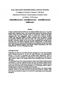
Figure 1. Configuration of a typical four-element OAM-generating array. (a) Horizontally polarized, OAM mode = +1. (b) Horizontally polarized, OAM mode = −1. (c) The LHCP antenna array and its polarization decomposition. (d) The RHCP antenna array and its polarization decomposition.
array system21,22, the Butler matrix23 or Rotman lens24 to generate OAM waves with different modes, but their design and architecture are all very complicated, which restrict the application. In this paper, we present a succinct solution of generating dual circularly-polarized (CP) dual-mode OAM radio beams. By sequentially rotating the dual-CP elements in the clockwise direction, the opposite phase differences are generated for left-handed CP (LHCP) and right-handed CP (RHCP), thus the dual-mode operation for OAM is achieved. Since the four elements are fed with the same phase for both LHCP and RHCP, the feed networks of the array are much simpler and ease of implementation. Simulation results and experimental measurements validate the effectiveness of the proposed design for generating dual-mode OAM beams.
Results
Theory and design for the dual OAM modes antenna. For a typical N-element OAM-generating cir-
cular phased array, the element should be fed with the uniform amplitude but with a successive phase difference for the successive elements, which is ∆φ = 2π /N (where is the topological charge, and < N /2)8,21. Figure 1(a,b) gives the geometry of a typical 4-element dipole array for OAM beams with modes = ±1. The phase difference for the successive elements in clockwise direction is 90° for OAM mode = +1, while the phase difference for OAM mode = −1 is −90°. In our work, four dual-CP patch elements are employed for building the OAM-generating array. Different from the common methods of array arrangement shown in Fig. 1(a,b), the four elements are fed with the same phase, but are sequentially rotated 90 degrees in the clockwise direction. The configuration of a LHCP array using sequentially rotated elements and its polarization decomposition are shown in Fig. 1(c), since a circular polarization can be seen as the superposition of two orthogonal line polarizations with 90° phase difference. When comparing Fig. 1(c) with Fig. 1(a), we can easily find that a 90° phase difference is obtained in successive elements for both horizontal and vertical polarizations after sequentially rotating the LHCP elements with 90° in the clockwise direction, thus the OAM mode = +1 is generated. As for a RHCP array shown in Fig. 1(d), when compared with Fig. 1(b), we can see that a −90° phase difference is obtained in successive elements for both horizontal and vertical polarizations after sequentially rotating the RHCP elements with 90° in the clockwise direction, thus the OAM mode = −1 is generated.
Structure of the dual OAM modes antenna. Based on the above-mentioned theories, we use four dual-CP elements to build the OAM-generating array. The four elements are sequentially rotated 90 degrees in the clockwise direction and fed with the same phase. To obtain a wideband operation, a dual-patch element is used, which are composed of three substrate layers and an air-gap, as shown in Fig. 2(a–c). The substrate used for the first and third layers is with the dielectric constant of 3.0 and height of 0.508 mm, while that for the second layer is with the dielectric constant of 3.0 and height of 0.762 mm. The circular parasitic patch is on the top surface of the Scientific Reports | 7:40099 | DOI: 10.1038/srep40099
2
www.nature.com/scientificreports/
Figure 2. Geometry of the antenna structure. (a) Element layered view. (b) Element side view. (c) Element Upward 2-D view. (d) Array side view. (e) Array upward 2-D view.
Figure 3. The simulated far-field phase distribution at 4.8 GHz. (a) = −1. (b) = +1.
first layer, with the radius of R = 12.8 mm. The driven patch is located on the top surface of second layer, with the radius of r = 9.8 mm. Between the first and second layers is an air-gap with a thickness of G = 4.335 mm, which is also helpful to obtain the broad bandwidth25. The metal ground plane is placed on the top surface of the third layer and fabricated with two apertures for the vias connection between the driven patch and the compact-size semi-lumped hybrid 90°coupler26 on the bottom surface of the third layer. The central angle of the two feeding point is 90° to excite the dual-CP operation, and this element structure is very similar to that shown in literature27; when one port is excited and the other terminated with a 50-Ω load, the LHCP or RHCP radiation will be generated correspondingly. The parameters of the hybrid coupler are set as follows:W = 1.4 mm, Lx = 10.8 mm, Ly = 10.3 mm, lx = 10.02 mm, ly = 10.1 mm, wx = 1.7 mm, wy = 2.3 mm. Figure 2(d,e) shows the overall geometry of the proposed antenna array, whose overall dimension is 104 mm × 104 mm, and the element spacing is 48 mm. When port I is excited and port II terminated with a 50-Ω load, the antenna array generates the LHCP wave with OAM mode = +1, whereas the RHCP wave with OAM mode = −1 is generated when port II is excited. The simulated far-field phase distribution of the antenna array is shown in Fig. 3, which is simulated with CST Microwave Studio software based on the finite integration technique (FIT) method. It is observed that, the phase distribution of the OAM waves undergoes a linear variation along the angular coordinate and the changing trends for = +1 and = −1 are in opposite directions.
Scientific Reports | 7:40099 | DOI: 10.1038/srep40099
3
www.nature.com/scientificreports/
Figure 4. Fabricated prototype of the antenna array. (a) Front view. (b) Back view. (c) The near-field test scenario in the anechoic chamber.
Figure 5. Measured S-parameters of the proposed antenna array.
Measurement of the antenna. To verify the proposed dual-CP dual-mode OAM array, the prototype
lens-fed array was fabricated by using the low-cost commercial printed-circuit-board (PCB) technology, and its measurement is carried out in the anechoic chamber, as shown in Fig. 4. Figure 5 shows the measured S-parameters, the measured reflection coefficient |S11| value for port I is below −10 dB from 3.94 to 5.35 GHz and achieves an impedance bandwidth of over 30%, the measured reflection coefficient |S22| value for port II is below −10 dB from 3.92 to 5.5 GHz and achieves an impedance bandwidth of 33.5%, and the ports transmission coefficient |S21| is lower than −10 dB from 4.26 to 5.18 GHz. The near field distribution of the antenna array is measured with a 3D platform in the near-field anechoic chamber, as shown in Fig. 4(c). An open-ended rectangular waveguide is used as the near-field probe, and the measuring plane is 300 mm far from the array plane with a scan range of 1180 mm × 1180 mm. Figure 6 gives the screenshots of the measured near-field results for both amplitude and phase distributions, and the red shadow in the amplitude distribution represents the high intensity, while the blue shadow in the center of the high-intensity region represents the low intensity. Note that, the on-axis singular-phase null regions are completely revealed, and the ocular null-region sizes of OAM modes = ±1 seem different but are actually with the same size, and this is mainly due to the large scale range in the default setting of the test instrument. The characteristic vortex phase Scientific Reports | 7:40099 | DOI: 10.1038/srep40099
4
www.nature.com/scientificreports/
Figure 6. Screenshots of the measured near-field results at 4.80 GHz. (a) Field amplitude and phase distribution for = −1. (b) Field amplitude and phase distribution for = +1.
Figure 7. Measured far-field results at 4.8 GHz. Intensity patterns: (a) = −1. (b) = +1. Phase distribution: (c) = −1. (d) = +1.
Scientific Reports | 7:40099 | DOI: 10.1038/srep40099
5
www.nature.com/scientificreports/
Figure 8. Measured and simulated 2D far-field results at 4.80 GHz. Radiation patterns: (a) = −1. (b) = +1. AR: (c) RHCP. (d) LHCP.
fronts indicate that the OAM radio beams are created, and the change in color from green to red, blue, and back to green again corresponds to a change in phase of 2π. When comparing the positive and negative modes, the phase distribution of = +1 has the clockwise increase, while that of = −1 would have the anticlockwise increase. The far-field radiations of the array are shown in Fig. 7, which are constructed from the near-field measurement by a two-dimensional fast Fourier transform (FFT) algorithm28. Figure 7(a,b) shows the intensity patterns, the doughnut-shaped high-intensity profile is clearly seen, and the null regions of OAM modes = ±1 have almost the same size. The far-field phase distributions for OAM modes = ±1 are plotted in Fig. 7(c,d), which show the rotating phase distribution. The simulated and measured 2D far-field radiation patterns are shown in Fig. 8(a,b), which are consistent very well each other. Good dual-CP conical patterns are generated, and the main lobe direction is around 27.5° from the boresight axis, with a 3-dB beamwidth of about 32.5°. The measured array gains are about 9 dBic at 4.80 GHz, and the on-axis null region is 25 dB lower than the high-intensity doughnut-shaped region for both LHCP and RHCP. The intensity of the cross-polarization field is much lower than that of the co-polarization field, and the cross polarization levels are lower than −20 dB for both LHCP and RHCP. The measured and simulated AR patterns for both LHCP and RHCP are shown in Fig. 8(c,d), and characteristic on-axis phase singularities of the OAM are also revealed on the AR-plots. Although there are some discrepancies due to the manual assembly error, the measured AR-plots are consistent with the simulated ones substantially and are below 2 dB for the peak radiation direction.
Discussion
A new convenience method of generating dual-CP dual-mode OAM radio beams has been presented in this paper. The dual-mode operation for OAM is achieved through the opposite phase differences generated for LHCP and RHCP, when the dual-CP elements are sequentially rotated in the clockwise direction. Since the four elements are fed with the same phase, the feed networks of the array are much simpler and ease of implementation. The measured results coincide well with the simulated ones, which verify the effectiveness of the proposed design and confirm the generation of the twisted radio beams operating at OAM mode = ±1. Since each of the OAM eigenstates with integral topological charges is orthogonal and independent of the other2,22, by combining the polarization discrimination with the orthogonal OAM states, the channel isolation of the communication system would have further improvement. All these features make the proposed antenna a promising candidate for radio communications and radar applications.
Scientific Reports | 7:40099 | DOI: 10.1038/srep40099
6
www.nature.com/scientificreports/
Methods
The dual-CP dual-mode OAM radio beams are generated through sequentially rotating the dual-CP elements in the clockwise direction. The dual-CP dual-mode OAM antenna is designed by CST Microwave Studio and manufactured on the Arlon AD300 substrates using the PCB technology. The measurement is carried out with a 3D platform in the anechoic chamber based on the Agilent Vector Network Analyzer 8722ES, and both intensity and phase distributions of the dual-mode OAM waves can be measured.
References
1. Dardari, D. & Tralli, V. High-speed indoor wireless communications at 60 GHz with coded OFDM. IEEE Trans. Commun. 47, 1709–1721 (1999). 2. Wang, J. et al. Terabit free-space data transmission employing orbital angular momentum multiplexing. Nature Photon. 6, pp. 488–496 (2012). 3. Cheng, D. K. Field and Wave Electromagnetics, 2nd ed. Reading, MA: Addison-Wesley, 1983. 4. Beth, R. A. Mechanical detection and measurement of the angular momentum of light. Phys. Rev. 50, 115–125 (1936). 5. Allen, L., Beijersbergen, M. W., Spreeuw, R. J. C. & Woerdman, J. P. Optical angular momentum of light and the transformation of Laguerre-Gauss laser modes. Phys. Rev. A 45, 8185–8189 (1992). 6. Guha, J. H. S. & Erkmen, B. I. Ultimate channel capacity of free-space optical communications. J. Opt. Netw. 4, 501–516 (2005). 7. Gibson, G. et al. Free-space information transfer using light beams carrying orbital angular momentum. Opt. Express 12, 5448–5456 (2004). 8. Thidé, B. et al. Utilization of photon orbital angular momentum in the low-frequency radio domain. Phys. Rev. Lett. 99, 087701 (2007). 9. Zelenchuk, D. & Fusco, V. Split-ring FSS spiral phase plate. IEEE Anten. Wireless Propag. Lett. 12, 284–287 (2013). 10. Schemmel, P., Maccalli, S., Pisano, G., Maffei, B. & Ng, M. Three-dimensional measurements of a millimeter wave orbital angular momentum vortex. Opt. Lett. 39, 626–629 (2014). 11. Cheng, L., Hong, W. & Hao, Z. Generation of electromagnetic waves with arbitrary orbital angular momentum modes. Sci. Rep. 4, 4814–4818 (2014). 12. Tamburini, F., Mari, E., Thidé, B., Barbieri, C. & Romanato, F. Experimental verification of photon angular momentum and vorticity with radio techniques. Appl. Phys. Lett. 99, 204102 (2011). 13. Tamburini, F. et al. Encoding many channels on the same frequency through radio vorticity: first experimental test. New J. Phys. 14, 033001 (2012). 14. Byun, W. et al. Simple generation of orbital angular momentum modes with azimuthally deformed Cassegrain subreflector. Electron. Lett. 51, 1480–1482 (2015). 15. Mari, E. et al. Near-Field Experimental Verification of Separation of OAM Channels. IEEE Antennas Wireless Propag. Lett. 14, 556–558(2015). 16. Bai, X. D. et al. Perforated dielectric antenna reflectarray for OAM generation,” In Proc. IEEE Antennas Propag. Soc. Int. Symp. 2015, 2159-2160. 17. Bai, Q., Tennant, A. & Allen, B. Experimental circular phased array for generating OAM radio beams. Electron. Lett. 50, 1414–1415 (2014). 18. Wei, W., Mahdjoubi, K., Brousseau, C. & Emile, O. Generation of OAM waves with circular phase shifter and array of patch antennas. Electron. Lett. 51, 442–443 (2015). 19. Spinello, F. et al. Experimental near field OAM-based communication with circular patch array. arXiv preprint arXiv:1507.06889 (2015). 20. Li, Z., Ohashi, Y. & Kasai, K. A dual-channel wireless communication system by multiplexing twisted radio wave. The 44th European Microwave Conference (EuMC). 2014, 235–238 (2014). 21. Mohammadi, S. M. et al. Orbital angular momentum in radio-a system study. IEEE Trans. Antennas Propag. 58, 565–572 (2010). 22. Bai, X. D., Jin, R. H., Liu, L., Geng, J. P. & Liang, X. L. Generation of OAM Radio Waves with Three Polarizations Using Circular Horn Antenna Array. International Journal of Anten. 2015, 132549 (2015). 23. Palacin, B., Sharshavina, K., Nguyen, K. & Capet, N. An 8 × 8 Butler matrix for generation of waves carrying Orbital Angular Momentum (OAM). 8th European Conf. Antennas and Propag. (EuCAP). 2814–2818 (2014). 24. Bai, X. D. et al. Rotman Lens-Based Circular Array for Generating Five-mode OAM Radio Beams. Sci. Rep. 6, 27815, doi: 10.1038/ srep27815 (2016). 25. Zhang, C. H., Liang, X. L., Bai, X. D., Geng, J. P. & Jin, R. H. A broadband dual circularly polarized patch antenna with wide beamwidth. IEEE Anten. Wireless Propag. Lett. 13, 1457–1460 (2014). 26. Sharaiha, A., Terret, C. & Blot, J. P. Printed resonant helix antenna with integrated feeding network. Electron. Lett. 33, 265–257 (1997). 27. Bai, X. D., Liang, X. L., Li, M. Z., Zhou, B., Geng, J. P. & Jin, R. H. Dual-Circularly Polarized Conical-Beam Microstrip Antenna. IEEE Anten. Wireless Propag. Lett. 14, 482–485 (2015). 28. Rahmat-Samii, Y., Galindo-Israel, V. & Mittra, R. A Plane-Polar approach for far-field construction from near-field Measurements. IEEE Trans. Antennas Propag. 28, 216–230 (1980).
Acknowledgements
This work was supported by the National Natural Science Foundation of China (61571298, 61571289 and 61471240), and the National Equipment Pre-Research Field Foundation of the 13th Five-Year Plan (6140135010116HG12001).
Author Contributions
X.-D.B. and X.-L.L. conceived the idea, and wrote the manuscript. R.-H.J. Y.-T.S. and P.-C.H. developed the method. Y.Y., K.W. and J.-P.G. performed the experiments and analysis. All authors contributed to the discussions and comments on the manuscript.
Additional Information
Competing financial interests: The authors declare no competing financial interests. How to cite this article: Bai, X.-D. et al. Experimental Array for Generating Dual Circularly-Polarized DualMode OAM Radio Beams. Sci. Rep. 7, 40099; doi: 10.1038/srep40099 (2017).
Scientific Reports | 7:40099 | DOI: 10.1038/srep40099
7
www.nature.com/scientificreports/ Publisher's note: Springer Nature remains neutral with regard to jurisdictional claims in published maps and institutional affiliations. This work is licensed under a Creative Commons Attribution 4.0 International License. The images or other third party material in this article are included in the article’s Creative Commons license, unless indicated otherwise in the credit line; if the material is not included under the Creative Commons license, users will need to obtain permission from the license holder to reproduce the material. To view a copy of this license, visit http://creativecommons.org/licenses/by/4.0/ © The Author(s) 2017
Scientific Reports | 7:40099 | DOI: 10.1038/srep40099
8