Available online at www.sciencedirect.com
ScienceDirect Procedia Engineering 158 (2016) 158 – 163
VI ITALIAN CONFERENCE OF RESEARCHERS IN GEOTECHNICAL ENGINEERING – Geotechnical Engineering in Multidisciplinary Research: from Microscale to Regional Scale, CNRIG2016
Experimental characterization and numerical investigation on the Azzone Visconti bridge in Lecco (Italy) Andrea Gallia,*, Paolo Martinellia a
Politecnico di Milano, Department of Civil and Environmental Engineering, P.za L. da Vinci 32, 20133, Milan (Italy)
Abstract The paper presents the results of a numerical investigation on the Azzone Visconti Bridge in Lecco (Italy). Starting from the historical data and from an extensive mechanical characterization of both the soil constituting the riverbed and of the masonry constituting the piers, the aim of the analyses is to predict the behaviour of the structure under the testing loading scheme prescribed by the current Italian Code. A finite element structural model has been conceived, and three different models describing the mechanical behaviour of the foundation have been implemented. Limited differences are observed in terms of absolute vertical settlement of the bridge, but important effects are highlighted in terms of stress redistribution within the piers. © by by Elsevier Ltd.Ltd. This is an open access article under the CC BY-NC-ND license © 2016 2016The TheAuthors. Authors.Published Published Elsevier (http://creativecommons.org/licenses/by-nc-nd/4.0/). Peer-review under responsibility of the organizing and scientific committees of CNRIG2016. Peer-review under the responsibility of the organizing and scientific committees of CNRIG2016 Keywords: Historical heritage; arch masonry bridge; soil-structure interaction; macroelement model; numerical analyses
1. Introduction Within the framework of an institutional collaboration between Politecnico di Milano (Polo Territoriale di Lecco) and the Municipality of Lecco (Italy), an extensive research activity involving several disciplines and research groups has been initiated in 2015 with the aim of characterizing the mechanical behavior of the Azzone Visconti Bridge in Lecco. The present work shows some preliminary numerical results concerning a finite element model of the structure, subjected to a loading scheme corresponding to that required by the current Italian Standards for a bridge of the first category. The bridge (also known as “Ponte Vecchio”) is a historical masonry arch bridge built in
* Corresponding author. Tel.: +39 0341 48 8860 E-mail address:
[email protected]
1877-7058 © 2016 The Authors. Published by Elsevier Ltd. This is an open access article under the CC BY-NC-ND license
(http://creativecommons.org/licenses/by-nc-nd/4.0/). Peer-review under the responsibility of the organizing and scientific committees of CNRIG2016
doi:10.1016/j.proeng.2016.08.422
Andrea Galli and Paolo Martinelli / Procedia Engineering 158 (2016) 158 – 163
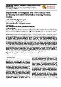
the XIV century consisting of ten piers, eleven arches and two bridge abutments, one on the Lecco side and one on the Milano side of the Adda river. During its life, the bridge experienced several modifications of length and use, hosting even (for a certain period) a military fortress with a drawbridge (Fig. 1a).
a
b
d
e
c
f
g Fig. 1. (a) Plot of the bridge in the XVI century; (b) view of the bridge in 1900; (c) tramway transit in 1910; (d) view of the works in 1960; (e) detail of the concrete caisson and of the external footbridges; (f) view of the bridge in 2014; (g) placement of the steel encasing ring and of the reinforcing concrete ring in 1960. Courtesy of Lecco Municipality and of Consorzio Fiume Adda.
At the beginning of the XX century, the existing structure (Fig. 1b) was reinforced to host a tramway (Fig. 1c). In 1960 important strengthening interventions were realized: the deck was completely removed (Fig. 1d) and a continuous concrete caisson (Fig. 1e) was inserted between the north and south masonry spandrel walls and filled with coarse granular material (mix of pebbles and mortar); external pedestrian footbridges were also added (Fig. 1f). The foundations of the piers have been reinforced by introducing a large diameter steel encasing ring (Fig. 1g) around each pier. The ring, about five meters depth, was finally constrained by and an additional external reinforcing concrete ring (also shown in Fig. 1g). During the works, the natural elevation of the riverbed was reduced of about two meters, in order to facilitate the outflow of the waters in the river. No further interventions were carried out in the last fifty years, with only a limited maintenance activity.
159
160
Andrea Galli and Paolo Martinelli / Procedia Engineering 158 (2016) 158 – 163
2. Geotechnical and structural characterization 2.1. Geotechnical characterization of the riverbed Five vertical cores (external diameter equal to 127 mm; diameter of the sample equal to 101 mm) have been drilled into the piers, one per each pier on the western half of the bridge, i.e. on the Milano side (Fig. 2a). The aim was to investigate the internal filling of the piers and, only for cores G10, G08 and G06, of the riverbed. In order to derive the grain size distributions, several (disturbed) soil samples were extracted from the riverbed. Within these three piers, several dynamic penetrometric tests (SPT) have been run at different depths. For cores G09 and G07 only, below the base of pier, SCPT tests (DPSH hammer) were performed up to a depth of about 26 meters from the deck, i.e. about 13 meters below the encasing steel ring (Fig. 2b).
a
b Fig. 2. (a) Plan and front views of the bridge: vertical cores and loading scheme; (b) SCPT-DPSH profiles and preliminary characterization.
Several layers of soils have been recognized by direct inspection of the extracted cores, ranging from gravel, to silty sand, to silty clay (the corresponding grain size curves have not been reported for the sake of brevity). Despite this large variability, all the foundations of the piers are stably positioned into a layer of a rather uniform gravelly sand (or fine gravel), approximately 9 meters thick. The whole set of penetrometric data were then interpreted by means of the well-known abaci proposed by [1,2], in order to estimate the relative density of the granular deposits. The correlations proposed by [3] have finally allowed to derive representative profiles of the values of the friction angle along the depth (Fig. 2b). For the sake of simplicity (and always being on the safe side) a homogeneous soil characterization has been assumed (DR|30%; I’=35°), corresponding with a mid loose granular material. 2.2. Mechanical characterization of the piers From the cores G06 and G09 it has been possible to select 13 cylindrical specimens (diameter D equal to 80 mm) at depths ranging between 1.5 m to 10.6 m from the deck. Six specimens are constituted by homogeneous rock, whilst seven specimens are made by mixed pebbles and mortar. An average density of to 2420 kg/m3 was estimated for the samples. All the specimens were analyzed by means of ultrasonic direct test [4], and an average ultrasonic speed of to 3.95 km/s has been measured. Seven cylindrical specimens with height H of 80 mm (H/D=1) were tested under uniaxial compression [5], whilst the remaining six with height H of about 40 mm (H/D=0.5) were tested under indirect tension (Brazilian test; [6]). Compression tests on homogeneous material provided values in the range of 50150 MPa, while specimens composed by mixed pebbles and mortar provide values around 20 MPa; Brazilian tests gave an average tensile strength equal to 3.5 MPa.
Andrea Galli and Paolo Martinelli / Procedia Engineering 158 (2016) 158 – 163
3. Definition of the numerical model 3.1. FE model of the bridge A bi-dimensional finite element (FE) model of the whole bridge was created by means of the software Abaqus/Standard [7]. The main geometrical characteristics of the structure (i.e. arches and piers) were derived from a topographical survey. The FE model combines several types of plane elements for different parts of the bridge as schematically indicated in Figure 3a. The piers and the filling material above the piers are discretized by employing plane stress elements, whilst the vaults are modelled with beam element. The top reinforced concrete (RC) caisson was modelled as an equivalent RC beam element connected to the vaults by means of equivalent springs (see Fig. 3a). These latter have been calibrated in order to reproduce the axial deformability of the caisson and of the spandrel walls. The vaults are rigidly connected to the piers (see point 6 of Fig. 3a). A linear elastic mechanical behaviour for all the aforementioned components have been assumed, since the loading scheme is not expected to induce significant non-linear effects in the structure.
a
b Fig. 3. (a) Main components of FE model for the Azzone Visconti bridge; (b) P- and S-waves velocity in loose sample of Ticino sand [8].
3.2. Mechanical behaviour of the foundations An average self-weight Q0=8000 kN was estimated for each pier and, according with the historical data, the estimated maximum traffic overload ever supported by each pier is 'Qmax=440 kN, corresponding with the transit of a very heavy truck in early Sixties. The piers are then expected to behave as slightly preloaded systems. The maximum expected final overload 'Qfin acting on each pier and corresponding to the prescribed loading test (see §3.3 for details), is about 600 kN, significantly exceeding the values 'Qmax. This will theoretically push the foundation into a virgin loading phase. To correctly model such transition, the pier foundation was described as a series of two 1D rheological elements (Fig. 3a), subjected to purely static vertical loads. Element 1 corresponds to the soil within the encasing ring, thought as a linear elastic spring of constant stiffness K1, modelling a “quasi” oedometric condition. All the non-linearities have instead been concentrated in Element 2, corresponding to the soil below the encasing ring, thought as an equivalent rectangular shallow foundation. 3.2.1. Characterization of Element 1 Because of technical (and budget!) limitations, an indirect strategy has then been adopted. Given the confinement provided by the encasing ring, and owing to the small amplitude of the applied load with respect to the static load ('Qfin/Q0