Mustafa Kemal Kulekci, Erdinç Kaluç, Aydın Şık, and Ozden Basturk
EXPERIMENTAL COMPARISON OF MIG AND FRICTION STIR WELDING PROCESSES FOR EN AW-6061-T6 (Al Mg1 Si Cu) ALUMINIUM ALLOY *Mustafa Kemal Kulekci Department of Mechanical Education Faculty of Tarsus Technical Education Mersin University 33480 Tarsus, Turkey.
Erdinç Kaluç Department of Mechanical Engineering Kocaeli University Kocaeli , Turkey
Aydın Şık Department of Industrial Education Faculty of Industrial Arts Education Gazi University Beşevler, Ankara, Turkey
and Ozden Basturk Faculty of Tarsus Technical Education Mersin University 33480 Tarsus, Turkey
اﻟﺨﻼﺻـﺔ: ﻲ EN AW-6061-T6اﻟﻤُﻮﺻﻠﺔ ﺑﻮﺳﺎﻃﺔ اﻟﻠّﺤﺎم ﺳﻮف ﺗﺘﻢ -ﻓﻲ هﺬا اﻟﺒﺤﺚ -دراﺳﺔ اﻟﺨﺼﺎﺋﺺ اﻟﻤﻴﻜﺎﻧﻴﻜﻴّﺔ ﻟﻮُﺻﻼت ﺧﻠﻴﻂ اﻷﻟﻤﻨﻴﻮم اﻟﻤﻌﺪﻧ ّ ي ﻟﻠﻤﻌﺎدن ،وذﻟﻚ ﻓﻲ ﺟ ّﻮ ﻣﻦ اﻟﻐﺎز اﻟﺨﺎﻣﻞ ) .(MIGوﻗﺪ ﺗ ّﻢ ﻲ )) (FSWﺑﺤﺮارة اﻻﺣﺘﻜﺎك واﻟﺘﺤﺮﻳﻚ( واﻟﻤُﻮﺻﻠﺔ ﺑﻮﺳﺎﻃﺔ اﻟﻠّﺤﺎم اﻟﺘﻘﻠﻴﺪ ّ ﻲ اﻻﺣﺘﻜﺎآ ّ اﻟﺘﺤﺮﻳﻜ ّ اﻟﺤﺼﻮل ﻋﻠﻰ ُوﺻﻼت FSWﺑﻮﺳﺎﻃﺔ ﺁﻟ ِﺔ ﺗﻔﺮﻳﺰ ﻧﺼﻒ أوﺗﻮﻣﺎﺗﻴّﺔ .وﻗﺪ ﺗﻤﺖ -ﻣﻦ ﺛ ّﻢ -ﻣﻌﺮﻓﺔ وﺗﺤﺪﻳﺪ أداء اﻟﻮُﺻﻼت اﻟﻤﻠﺤﻮﻣﺔ ﺑﻮﺳﺎﻃﺔ آﻼ اﻷﺳﻠﻮﺑﻴﻦ ) FSWو (MIGﻋﺒﺮ إﺟﺮاء اﺧﺘﺒﺎرات اﻟﺸ ّﺪ واﻟﻜَﻼل واﻟﺼّﻼدة واﻟﺼّﺪم .وﻗﺪ ﺗ ّﻢ أﻳﻀًﺎ ﺗﻘﻴﻴﻢ اﻟﻮُﺻﻼت اﻟﻤﻠﺤﻮﻣﺔ ﺑﻮﺳﺎﻃﺔ اﻟﻌﻤﻠﻴّﺘﻴﻦ اﻟﻤﺬآﻮرﺗﻴﻦ أﻋﻼﻩ ﻣﻦ ﺣﻴﺚ اﻻﻋﻮﺟﺎج اﻟﻤُﺼﺎﺣﺐ ﻋﺎد ًة ﻟﻌﻤﻠﻴّﺎت اﻟﻠّﺤﺎم .وﻗﺪ ﺗﻤﺖ أﻳﻀًﺎ -أﺧﺬًا ﻷوﺿﺎع ﻋﻤﻠﻴّﺔ اﻟﻠّﺤﺎم وﻣﺘﻄﻠﺒﺎﺗﻬﺎ ﺑﻌﻴﻦ اﻻﻋﺘﺒﺎر -ﻣﻘﺎرﻧ ُﺔ اﻟﻌﻤﻠﻴّﺘﻴﻦ ﺑﻌﻀﻬﻤﺎ ﺑﺒﻌﺾ ﻲ اﻟﻤﺴﺘﻬﺪف ﻓﻲ هﺬﻩ اﻟﺪراﺳﺔ .وﻗﺪ ﺑﺪت وُﺻﻼت FSW ﻞ ﻣﻦ اﻟﻔﻮاﺋﺪ واﻟﻤﻀﺎ ّر ﻟﺘﻄﺒﻴﻖ ﻋﻤﻠﻴّﺘﻲ اﻟﻠّﺤﺎم ﻋﻠﻰ ﺧﻠﻴﻂ اﻷﻟﻤﻨﻴﻮم اﻟﻤﻌﺪﻧ ّ ،وذﻟﻚ ﻟﻤﻌﺮﻓﺔ وﻓﻬﻢ آ ّ ﻞ اﺗّﺴﺎﻋًﺎ ﻓﻲ ن اﻟﻨّﻄﺎق اﻟﻤُﺘﺄﺛّﺮ ﺑﺎﻟﺤﺮارة آﺎن أﻗ ّ اﻟﻤﻠﺤﻮﻣﺔ ﻋﻠﻰ ﻣُﻘﺎوﻣﺔ ﻟﻠﺸ ّﺪ وﻣُﻘﺎوﻣﺔ ﻟﻠﻜَﻼل وﻣُﻘﺎوﻣﺔ ﻟﻠﺼّﺪم أﻓﻀﻞ ﻣﻦ اﻟﻮُﺻﻼت اﻷﺧﺮى .ﻳُﻀﺎف إﻟﻰ ذﻟﻚ أ ّ ن ﻋﻤﻠﻴّﺔ FSWﺗﺆ ّدي إﻟﻰ ﺗﺤﺴﻴﻦ اﻟﺨﺼﺎﺋﺺ اﻟﻤﻴﻜﺎﻧﻴﻜﻴّﺔ ﻟﻠﻮُﺻﻼت اﻟﻤﻠﺤﻮﻣﺔ. وُﺻﻼت FSWﻣﻨﻪ ﻓﻲ وُﺻﻼت .MIGﻟﺬا ﻓﻘﺪ أﻇﻬﺮت اﻟﻨﺘﺎﺋﺞ أ ّ
*Corresponding Author: E-mail address:
[email protected] Paper Received January 24, 2006; Paper Revised March 31, 2009; Paper Accepted June 29, 2009
321
The Arabian Journal for Science and Engineering, Volume 35, Number 1B
April 2010
Mustafa Kemal Kulekci, Erdinç Kaluç, Aydın Şık, and Ozden Basturk
ABSTRACT In this study, the mechanical properties of welded joints of EN AW-6061-T6 aluminium alloy obtained with friction stir welding (FSW) and conventional metal inert gas welding (MIG) are studied. FSW welds were carried out on a semi-automatic milling machine. The performance of FSW and MIG welded joints were identified using tensile, fatigue, hardness, and impact tests. The joints obtained with FSW and MIG processes were also assessed for distortion that accompanied the welding processes. Taking into consideration the process conditions and requirements, FSW and MIG processes were also compared with each other to understand the advantages and disadvantages of the processes for welding applications of studied Al alloy. Better tensile, fatigue, and impact strength were obtained with FSW welded joints. The width of the heat affected zone of FSW was narrower than MIG welded joints. The results show that FSW improves the mechanical properties of welded joints. Key words: friction stir welding, friction welding, joining, new welding technologies, mechanical properties
322
The Arabian Journal for Science and Engineering, Volume 35, Number 1B
April 2010
Mustafa Kemal Kulekci, Erdinç Kaluç, Aydın Şık, and Ozden Basturk
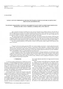
EXPERIMENTAL COMPARISON OF MIG AND FRICTION STIR WELDING PROCESSES FOR EN AW-6061-T6 (Al Mg1 Si Cu) ALUMINIUM ALLOY 1. INTRODUCTION Friction Stir Welding (FSW) is a solid state welding process which was developed and patented by the welding institute (TWI-UK) for ferrous and non-ferrous materials [1,2,3]. The process is repeatable, can be monitored, and does not produce major safety hazards, such as fumes or radiation [2,4,5]. The FSW process can be implemented with a conventional milling machine [5,6]. The FSW tool is generally made with a profiled pin, which is contained in a shoulder with a larger diameter than that of the pin as seen in Figure 1. The tools are manufactured from a wear resistant material with good static and dynamic properties at elevated temperatures [7,8]. A properly designed tool permits up to 1000 m of weld to be produced in 5 mm thick aluminium extrusions. The tool is shaped with a large diameter shoulder and a small diameter profiled pin that first makes contact as it is plunged into the joint region [7]. The plates to be welded are fixed rigidly to prevent the joint faces from being forced apart as the probe passes through and along the seam [8–12]. For thick plate welding, usually a pilot hole of smaller diameter than that of the profiled pin is drilled at the start to assist the plunging of the tool [13,14]. The depth of penetration is controlled by the length of the profiled pin below the shoulder of the tool [15]. The initial plunging friction contact heats the adjacent metal around the probe as well as a small region of material underneath the probe, but the friction between shoulder and material interface generates significant additional heat to the weld region [16]. In addition to generating heat, the shoulder of the tool also prevents highly plasticized material from being expelled from the welding region [17–19]. The thermally softened and heat-affected zone takes up a shape corresponding to that of the overall tool geometry [20]. The heat-affected zone is much wider at the top surface and tapers down towards the tip of the tool [21]. The combined frictional heat from the profiled pin and the shoulder creates a highly plasticized condition around the immersed probe [22–24]. This plasticized material provides a hydrostatic affect as the rotating tool moves along the joint, which helps the plasticized material to flow around the tool [25,26]. It then coalesces behind the tool as the latter moves along the weld line [27]. For butt joining, the length of the pin approximates to the thickness of the work-piece if the weld is done from one side. For a double-sided weld, the length of the pin is approximately equal to half of the welded plate thickness [14]. The onion-ring like structure of the nugget is typically of high quality stir weld, in which no porosity or internal voids are detectable [28]. In macro-sections of good quality welds, the nugget is visible at the center of the weld, as shown schematically in Figure 1. Outside the nugget, there is a thermo-mechanically affected zone, which has been severely plastically deformed and shows some areas of partial grain refinement [29]. The main application of FSW is in the production of long-straight welds in aluminium alloy plates, extruded aluminium profiles, and tailored blanks [6]. Lightweight aluminium alloys are used widely in applications such as aerospace and transportation (ship panels, the frames of high speed railway and automobile parts) [30]. The joints obtained with FSW reduce up to 30% the involved costs compared to mechanical fastening together with a weight reduction of 10%. On the other hand, traditional welding processes present a series of disadvantages when applied to Al alloys [1].
Figure 1. a) Friction stir welding principle and microstructure (SZ: strirring zone, TMAZ: thermo-mechanically affected zone – transition zone, UZ: unaffected zone – base metal, AS: advancing side, RS: retreating side), b) FSW application on milling machine, c) FSW tool used in the study
In this study, Metal Inert Gas welding (MIG) and FSW processes are experimentally compared and assessed using the experimental results obtained from mechanical tests performed on the welded joints of EN AW-6061-T6 aluminium alloy.
April 2010
The Arabian Journal for Science and Engineering, Volume 35, Number 1B
323
Mustafa Kemal Kulekci, Erdinç Kaluç, Aydın Şık, and Ozden Basturk
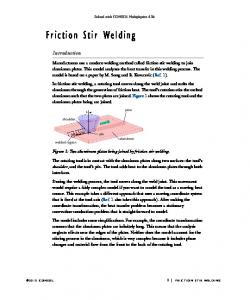
2. EXPERIMENTAL STUDIES The material used in this study was commercially available EN AW-6061-T6 (AlMg1SiCu) aluminium alloy. The welded plates were 300 mm in length, 125 mm in width, and 5 mm in thickness. The mechanical properties are given in Table 1. FSW joints were carried out using a semiautomatic milling machine. The diameter of the tool shoulder was 20 mm and that of the insert pin and height were 5 mm and 4.85 mm, respectively, as seen in Figure 1. FSW was carried out at a constant tool rotation of 1600 rpm and a transverse speed of 200 mm/min. The thread of the pin was machined as right hand form. The tool was rotated counter-clockwise to force softened material towards the root of the weld and to obtain a full joint at the root of the weld. The butted plates were clamped on a steel backing plate. The rotating tool was fixed to the spindle of the milling machine and tilted 1.5o away from the spindle’s travel path, as seen in Figure 1c. In the FSW procedure, firstly, the surface of the work-piece brought into contact with the shoulder and insertion of the rotating FSW tool was stopped. At this stage, to generate the required pre-frictional heating, the shoulder of the rotating tool was held in its initial position for 60 seconds rubbing with the surface of the work-piece. Then the rotating tool was moved along the joint line. The rolling direction of the plates was perpendicular to the direction of the weld run. Single-sided welds were applied to the plates. Typically, the surface appearance of FSW was a regular series of partially circular ripples, which point towards the start of the weld. These ripples were essentially cycloid and were produced by the final sweep of the trailing circumferential edge of the shoulder during traverse. The surface color of FSW was silvery-white for studied material. The surface appearance of the weld was similar to the surface obtained by milling. Another set of the Al alloy plates was butt welded (single sided I-joint) using the MIG process. The plates were cleaned before the MIG welding procedure with a scraper and acetone. In the MIG welding process, a MIG-350 type semiautomatic welding machine was used for welding the plates with the parameters of 240± A (current) and 24±1 V (voltage). A 4145 filler of 1.2 mm diameter with a welding speed of 110mm per minute was used to carry out the MIG welds. In the MIG process, shielding was provided by argon gas at a flow rate of 18 l.min-1. To evaluate and compare the mechanical properties of the joints obtained with MIG and FSW processes, tensile, charpy impact, Brinell hardness, and three-point bending fatigue tests were performed on welded joints. The MIG and FSW processes were also compared for distortions that accompanied welds, relative cost, and welding speed. The dimensions of the tensile and fatigue tests are given in Figure 2. The tensile test specimens were machined out according to dimensions given in EN 895. The specimens of the welded plates that joined with FSW and MIG processes were taken in traverse direction of weld line. Fatigue tests were carried out using a three-point bending fatigue test machine. Fatigue tests were made using 8 specimens for base material and for each group of welded joints. Fatigue endurance limit was taken as 1.0E+07 cycle for base, MIG, and FSW joints as recommended in literature to specify the useful service life of the welded joints [30]. Charpy Impact tests with V-notch were performed according to EN 10045 at room temperature to evaluate the impact strength of MIG and FSW joints. The impact test specimens were machined out with dimensions of 55mm in length and the square section with 10mm sides. The specimens were prepared as V notch form with 45o angle and 2 mm depth with a 0.25 mm radius of curve at the root of the notch. Brinell hardness tests were performed on welded joints using a AFFRI-OMAG Brinell Hardness Tester with 62.5 kg load to compare and assess the hardness distribution of the FSW and MIG welds. Both of the processes were also compared for relative cost, welding speed, and distortion that came out after welding processes. Table 1. Mechanical Properties of EN AW-6061-T6 Al Alloy Rm (MPA) Min
Max
290
Rp0,2 (MPa) Min
Max
240
Elongation (%) A50 10
A
Hardness (HB) 80
3. RESULTS and DISCUSSION Macrographs of the MIG and FSW welded joints of EN AW-6061-T6 (AlMg1SiCu) aluminium alloy are given in Figure 3. The surface appearance and roughness of the FSW weld is similar to the surface obtained by the milling process. The surface of the MIG welds is similar to the cast structure and has a rougher surface. The tensile specimens machined from welded plates are not fractured at the weld zone but at the heat affected zone. The average tensile test strength of FSW, MIG weld, and base metal (BM) were 270, 220, and 290 MPa, respectively, as seen in Figure 4a. Tensile strength of FSW was 7% lower than BM. On the other hand, strength decrease was about 24% in MIG welded specimens. The results of the tensile tests show that 22% strength improvement can be obtained with the FSW process when compared with MIG. The tensile strength of the FSW joint is stronger than the MIG joint, but lower than the base metal as seen in Figure 4. This strength improvement can be explained with the structure obtained with the FSW process. The studies in the literature report that the microstructure of FSW is a refined structure, while MIG welds have a cast structure [5,6,8,24]. The stirring effect of the FSW process gives a finer microstructure to the weld. On the other hand, in the MIG welding process, a coarser columnar crystalline structure is obtained [2,7,8]. The stirring effect and refined structure improve the mechanical properties of the FSW joint. The
324
The Arabian Journal for Science and Engineering, Volume 35, Number 1B
April 2010
Mustafa Kemal Kulekci, Erdinç Kaluç, Aydın Şık, and Ozden Basturk
elongation values of the tested specimen were 12%, 11%, 6% for base, FSW, and MIG welded specimens, respectively, as seen in Figure 4.b. Fatigue test results of FSW, MIG joints, and base metal are given in Figure 5. For the same endurance limit (1.0E+07 cycles), the stress amplitudes for MIG, FSW joints, and BM were about 78, 96, and 125 MPa, respectively, as seen in Figure 5. The fatigue test results show that 23 % fatigue strength improvement can be obtained in joints using the FSW process instead of MIG for the studied Al alloy material. The impact strength of base metal, FSW, and MIG welds were defined by a Charpy Impact test. The results of the Charpy Impact test carried out at room temperature are given in Figure 6. The impact strength of the base metal, FSW, and MIG welds are the mean of 4 specimens. The impact strength value of FSW was greater than MIG joints and BM. This situation can be explained with the grain refinement of the stirring effect in the FSW process. The impact strength of the FSW joint was 11% greater than that of the parent material and 36% greater than MIG joints. The impact strength of the joints obtained with FSW is 8J higher than the MIG welded joints. This impact strength difference is related to the weld structures obtained with FSW and MIG processes. FSW joints have better impact strength than MIG for studied material. The stirring effect of FSW improves the microstructure of the weld and increases the resistance to impact. Hardness distribution on the surface of the FSW and MIG welded joints perpendicular to the weld line is given in Figure 7, which shows that the region where hardness decreases is narrower for FSW than MIG welds. From this result, it is seen that the heat-affected zone of FSW is narrower than the MIG welded joints. Taking into consideration the 20 mm diameter of FSW tool, the hardness reduction region of the MIG joints are wider because of higher heat input. The difference between the hardness reduction regions of the FSW and MIG joints can be explained by the fact that the welding temperature that FSW welds at is about 480oC [19,22,28], far lower than that of the MIG process. The joints obtained with the FSW and MIG processes were also assessed for distortions that accompanied the welding processes. The distortions accompanied to joints are given in Figure 8. The distortion that accompanies the FSW process is much lower than that of the MIG process. Lower heat input in the FSW process resulted in better dimensional accuracy and lower distortion when compared with the MIG process. MIG welded joints result in greater distortion due to an increase in the amount of heat input. FSW welds can be done by an ordinary milling operator. On the other hand, MIG welds have to be done by a certified MIG weld operator. Relative workmanship costs per part and welding speeds for FSW and MIG processes are given in Figures 9 and 10, respectively. The relative workmanship costs were obtained from workmanship wages in Turkey. The FSW process has higher performance in the production rate and quality as well as a decrease in production costs, as seen in Figures 9 and 10. The MIG welding process needed a qualified welder but an ordinary milling operator with basic skills for milling was enough to join the plates by FSW on a milling machine.
Figure 2. a) Dimensions of tensile test specimens, b) Dimensions of fatigue test specimen
a)
b)
Figure 3. a) Macrograph of FSW weld, b) Macrograph of MIG welded joint
April 2010
The Arabian Journal for Science and Engineering, Volume 35, Number 1B
325
Mustafa Kemal Kulekci, Erdinç Kaluç, Aydın Şık, and Ozden Basturk
350
Ultimate tensile strength (MPa) 290
300
270 250
Rm (MPa)
220 200
150
100
50
0
Base metal
FSW
MIG
a 14 12
12
11
Elongation (%)
10 8 6
6 4 2 0 Base metal
FSW
MIG
b Figure 4. Tensile test results of base metal and cross-welded joints a) ultimate tensile strength, b) elongation
Stress range (MPa)
180
MIG Joint FSW Joint Base Metal L (B M t l)
160 140 120 100 80 60 40 20 0 0.0E+00
2.0E+06
4.0E+06
6.0E+06
8.0E+06
1.0E+07
1.2E+07
1.4E+07
1.6E+07
Number of cycles to failure
Figure 5. Fatigue test results of FSW, MIG joints and base metal
326
The Arabian Journal for Science and Engineering, Volume 35, Number 1B
April 2010
Mustafa Kemal Kulekci, Erdinç Kaluç, Aydın Şık, and Ozden Basturk
35
30
Impact strength (J)
30
27
25
22
20 15 10 5 0
Base metal
FSW
MIG
Figure 6. Impact strength of FSW, MIG and base metal (FSW: Friction stir weld, MIG: Metal inert gas arc welding, base metal: EN AW-6061-T6 (Al Mg1 Si Cu) aluminium alloy)
Figure 7. Hardness distributon at the surface of FSW and MIG welded specimens
Distortion - shortening (mm)
12
11
MIG
10
FSW 8
6
4
3,2
2 0,1
0,4
0,6
0,1
0 Distortion at corners
Vertical distortion
Horizontal distortion
Figure 8. The amount of the distortion / shortening in FSW and MIG welded specimens
April 2010
The Arabian Journal for Science and Engineering, Volume 35, Number 1B
327
Mustafa Kemal Kulekci, Erdinç Kaluç, Aydın Şık, and Ozden Basturk
1.2
1 Relative cost /part
1 0.8
0.65 0.6 0.4 0.2 0
FSW
MIG
Figure 9. Relative cost / part for FSW and MIG processes 400 350
Welded length (mm)
Welded length (mm/minute)
350
300
250
200
150 110 100
50
0 FSW
MIG
Figure 10. Welding speed of FSW and MIG processes
4. CONCLUSION The conclusions can be summarized as follows: •
The tensile, impact, and fatigue strength of welded joints can be increased using the FSW process instead of MIG.
•
Hardness change in the welded material is affected from the amount of the heat input during the welding process. Less heat input in the FSW process lowers the area where hardness changes.
•
The heat-affected zone of FSW is narrower than the MIG process. The shoulder diameter of FSW welds and heat input during the welding process determines the width of the hardness reduction region.
•
Higher heat intensity in the MIG process negatively affects the mechanical properties of the welded material.
•
Higher performance in production rate and quality, as well as decreasing production costs, can be obtained by FSW welding. The required pre-operations before the welding process are very limited in FSW. This feature of the FSW process saves consumable material time cost and improves the quality of the welds.
ACKNOWLEDGMENT This article was prepared with the support of the Research Foundation of Mersin University under project of 2003/2.
328
The Arabian Journal for Science and Engineering, Volume 35, Number 1B
April 2010
Mustafa Kemal Kulekci, Erdinç Kaluç, Aydın Şık, and Ozden Basturk
REFERENCES [1]
M. Cabibo, E. Meccia, and E. Evangelista, “TEM Analysis of a Friction Stir-Welded Butt Joint of Al–Si–Mg Alloys”, Materials Chemistry and Physics, 81(2003), p. 289.
[2]
M. K. Kulekci, “Mechanical Properties of Friction Stir-Welded Joints of AlCu4SiMg Aluminium Alloy”, Kovove Materialy, 41(2)(2003), p. 97.
[3]
W. M. Thomas, P. L. Threadgil, and E. D. Nicholas, “Feasibility of Friction Stir Welding”, Science and Technology of Welding and Joining, 4(1999), p. 365.
[4]
Won-Bae Lee and Seung-Boo Jung, “The Joint Properties of Copper by Friction Stir Welding”, Materials Letters, 58(6)(2004), p. 1041.
[5]
M. K. Kulekci, F. Mendi, I. Sevim, and O. Basturk, “Fracture Toughness of Friction Stir-Welded Joints of AlCu4SiMg Aluminium Alloy”, Metalurgija, 44(3)(2005), p. 209.
[6]
E. Taban and E. Kaluç, “EN AW-5083-H231 Alüminyum Alaşımının MIG, TIG ve Sürtünen Eleman ile Birleştirme (FSW) Kaynaklı Bağlantılarının Mekanik ve Mikroyapısal Özellikleri”, Mühendis ve Makina, 46(541)(2005), p. 40.
[7]
G. Çam, “Sürtünme Karıştırma Kaynağı (SKK): Al-Alaşımları İçin Geliştirilmiş Yeni Bir Kaynak Teknolojisi”, Mühendis ve Makine, 46(541)(2005), p. 30.
[8]
G. Çam, V. Ventzke, J. F. Dos Santos, M. Koçak, G. Jennequin, and P. Gontier-Maurin, “Characterisation of Electron Beam Welded Aluminium Alloys”, Science and Technology of Joining and Welding, 4(1999), p. 317.
[9]
M. Ericson and R. Sandström, “Influence of Welding Speed on the Fatigue of Friction Stir Welds, and Comparison With MIG and TIG”, International Journal of Fatigue, 25(2003) p. 1379.
[10]
H. Uzun, C. D. Donne, A. Argagnotto, T. Ghidini, and C. Gambaro, “Friction Stir Welding of Dissimilar Al 6013-T4 To X5CrNi18-10 Stainless Steel”, Materials & Design, 26(2005), p. 41.
[11]
N. Saito, I. Shigematsu, T. Komaya, T. Tamaki, G. Yamauchi, and M. Nakamura, “Friction Stir Welding of Dissimilar Al 6013-T4 to X5CrNi18-10 Stainless Steel”, Journal of Materials Science Letters, 20(2003), p. 1913.
[12]
T. L. Dickerson and J. Przydatek, “Fatigue of Friction Stir Welds in Aluminium Alloys that Contain Root Flaws”, International Journal of Fatigue, 25(2003), p. 1399.
[13]
G. Çam, “Kaynak Teknolojisindeki Gelişmeler”, Kaynak Teknolojileri V. Ulusal Kongresi, Kocaeli, 2005, s. 87–89.
[14]
M. K. Kulekci and A. Şık, “Sürtünme Karıştırma Kaynağı ile Alüminyum Alaşımı Levhalarının Birleştirilmesi ve Elde Edilen Kaynaklı Bağlantıların Özellikleri”, S.D.Ü. Dergisi, 7(3)(2003), p. 93.
[15]
C. B. Smith, J. F. Hinrichs, W. A. Crusan and J. Leverett, “FSW Stirs Up Welding Process Competition”, www.sme.org/forming &fabricating, 2(2003).
[16]
R. A. Prado, L. E. Murr, K. F. Soto, and J. C. McLure, “Self-Optimization in Tool Wear for Friction-Stir Welding of Al 6061+20% Al2O3 MMC ”, Materials Science & Engineering A, 349(1–2)(2003), p. 156.
[17]
T. J. Lienert, W. L. Stellwag, J. B. B. Grimmett, and R. W. Warke, “Friction Stir Welding Studies on Mild Steel”, Welding Research, January(2003), p. 1.
[18]
K. Colligan, “Material Flow Behaviour During Friction Stir Welding of Aluminium”, Welding Research, July(1999), p. 229.
[19]
R. W. Fonda, J. F. Bingert, and K. J. Colligan, “Development of Grain Structure During Friction Stir Welding”, Scripta Materialia, 51(3)(2004), p. 243.
[20]
W. M. Thomas, K. I. Johnson, and C. S. Wiesner, “Friction Stir Welding – Recent Developments in Tool and Process Technologies”, Advanced Engineering Materials, 5(7)(2003), p. 485.
[21]
W. M. Thomas and E. D. Nicholas, Materials & Design, 4(6)(2003), p. 269.
[22]
O. V. Flores, C. Kennedy, L. E. Murr, D. Brown, S. Pappu, B. M. Nowak, and J. C. McClure, “Microstructural Issues in a Friction-Stir-Welded Aluminum Alloy”, Scripta Materialia, 38(5)(1998), p. 703.
[23]
Ying Li, L. E. Murr, and J. C. McClure, “Solid-State Flow Visualization in the Friction-Stir Welding of 2024 Al to 6061 Al”, Scripta Materialia, 40(9)(1999), p. 1041.
[24]
K. V. Jata and S. L. Semiatin, “Continuous Dynamic Recrystallization During Friction Stir Welding of High Strength Aluminum Alloys”, Scripta Materialia, 43(8)(2000), p. 743.
April 2010
The Arabian Journal for Science and Engineering, Volume 35, Number 1B
329
Mustafa Kemal Kulekci, Erdinç Kaluç, Aydın Şık, and Ozden Basturk
330
[25]
S. Benavides, Y. Li, L. E. Murr, D. Brown, and J. C. McClure, “Low-Temperature Friction-Stir Welding of 2024 Aluminum”, Scripta Materialia, 41(8)(1999), p. 809.
[26]
S. W. Williams, “Welding of Airframes Using Friction Stir”, Air and Space Europe, 3(3–4)(2001), p. 64.
[27]
K. N. Krishnan, “On the Formation of Onion Rings in Friction Stir Welds”, Materials Science and Engineering A, 327(2)(2002), p. 246.
[28]
K. A. A. Hassan, A. F. Norman, D. A. Price, and P. B. Prangnell, “Stability of Nugget Zone Grain Structures in High Strength Al-Alloy Friction Stir Welds During Solution Treatment ”, Acta Materialia, 51(7)(2003), p. 1923.
[29]
J. Q. Su, T. W. Nelson, R. Mishra, and M. Mahoney, “Microstructural Investigation of Friction Stir Welded 7050T651 Aluminium”, Acta Materialia, 51(3)(2003), p. 713.
[30]
S. Kalpakjian, Manufacturing Engineering Technology. Addison-Wesley, 1995, p. 36.
The Arabian Journal for Science and Engineering, Volume 35, Number 1B
April 2010