Experimental Demonstration of a Non-orthogonal Multiple Access Scheme for Visible Light Communications with SCFDM Transmission
1
Bangjiang Lin (
[email protected]), 2,3Zabih Ghassemlooy (
[email protected]), Xuan Tang (
[email protected]), 1Chun Lin (
[email protected]) and 1Zhenlei Zhou (
[email protected]) 1 Quanzhou Institute of Equipment Manufacturing, Haixi Institutes, Chinese Academy of Sciences, Quanzhou, China; 2Optical Communications Research Group, Faculty of Engineering and Environment, Northumbria University, Newcastle, U.K; 3College of Engineering, Huaqiao University, Quanzhou, China Corresponding authors: Bangjiang LIN and Xuan TANG 1
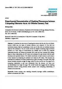
Abstract We experimentally demonstrate a hybrid non-orthogonal multiple access (NOMA) and single carrier division multiplexing (SCFDM) transmission scheme for visible light communications, which offers higher spectral efficiency, improved tolerance against multi-path and a good balance between the data throughput and fairness. Compared with the orthogonal frequency division multiplexing based NOMA, NOMA-SCFDM with lower peak to average power ration offers enhanced tolerance to the light emitting diode nonlinearity and improved bit error rate performance. Keywords Visible light communications (VLC), Non-orthogonal multiple access (NOMA), Single carrier division multiplexing (SCFDM) 1. Introduction The continuous growth in wireless data traffic has led to the development of the next generation mobile communication networks to address several critical challenges, such as broadband capacity, spectral efficiency, energy efficiency, mobility coverage, and quality-of-services. These challenges are being address with the existing radio frequency (RF) based wireless technologies by adopting multi-level and multi-carrier modulation and coding schemes, massive multiple input multiple outputs (MIMO), millimeter wave (20-100 GHz), spectral haring and hoping, etc. [1-2]. However, the frequency spectrum is a precious and costly resource, and its availability is still a major issue, and therefore better utilization of the RF spectrum in places where it is needed the most would be one option. Therefore, in order to release the pressure on the RF spectrum and more specifically in indoor environments, one interesting option is to utilize the visible band (390 – 700 nm, i.e., 430-770 THz) of the electromagnetic spectrum. Visible light communications (VLC) – also known in the commercial domain as LiFi - is a truly a green technology, which utilizes the light emitting diodes (LEDs) based lights to offer data communications as well as indoor positioning, and has a number of key features including low cost, license-free, higher luminance efficiency, inherent security and immunity to the RF electromagnetic interference [3-6]. In the last few years we have seen a growing research activity in VLC and its applications including intelligent transportation systems (ITS), medical, manufacturing, indoor positioning, airport, trains and train station, offices, etc. [3-6]. Most of the recent advances made in VLC are for point-to-point (i.e., line of sight) transmission. Considering that the coverage area offered by a single LED is limited, and therefore for large indoor environments higher number of LEDs will be needed to ensure both uniform illumination and adequate communication coverage with a high quality of service. In order to further increase data rate in VLC systems, there are a number possible options including equalization, high-level modulation
scheme, and multiple access (MA), etc. The MA scheme implemented in the physical layer is a desirable option with the potential of efficiently sharing the available network resources between users in indoor environments (i.e., home, office, etc.) [7]. The widely adopted MA schemes in RF wireless communication both in both time and frequency domains are time division multiple access (TDMA), frequency division multiple access (FDMA), code division multiple access (CDMA) and orthgonal frequency domian multiple access (OFDMA), which can be applied to VLC systems [8-9]. In addition to these we also have wavelength division multiple access (WDMA) and space division multiple access (SDMA) techniques that are used in indoor VLC systems [10-11]. In 3.9/4G, the OFDMA or single carrier-FDMA (SC-FDMA) is adopted in order achieve higher throughput performance. OFDM offers robustness against multipath induced interference and good affinity to the MIMO technology, which increases the achievable data rate. MA can also be implemented in the power domain, where both time and frequency resources are shared simultaneously between the users by means of power domain multiplexing. The non-orthogonal multiple access (NOMA) is a power domain multiplexing scheme, which is being proposed for the 5th generation (5G) wireless communication networks because of its enhanced spectral efficiency and ubiquitous connectivity features [12-14]. NOMA has interesting features including (i) multiple users can transmit and receive information at the same time over the same frequency band but using different power levels; (ii) redundancy can be introduced by means of coding in the power domain (i.e., allocating higher power levels to users with worse channel conditions) at the Tx initiatively and uses successive interference cancellation (SIC) to separate the users at the receivers (Rxs); and (iii) superior performance gains at higher signal-to-noise (SNR) levels [15]. The latter is particularly attractive for VLC systems, which normally operate at higher SNR levels due to shorter transmission spans and presence of strong line-of-sight (LOS) paths. NOMA is an efficient MA for indoor environments and is adopted to increase the throughput in downlink VLC systems [16-21]. In [16], the NOMA scheme was introduced in VLC incorporating a novel gain ratio power allocation strategy in order to enhance the system performance. In [17] it was shown that NOMA outperforms OFDMA in terms of the achievable data rate. In [20] experimental demonstration of NOMA-OFDMA VLC was carried out to demonstrate high throughput and higher spectral efficiency. In [19], a phase pre-distortion method was proposed to improve the symbol error rate performance of the NOMA uplink with SIC decoding in VLC. In [21], the analysis of the bit error rate (BER) performance in a downlink VLC network based on NOMA is provided. However, due to the high peak to average power ratio (PAPR) of the signal OFDM, in VLC systems both LED and amplifiers should be characteristics to operate in the most linear region in order to avoid excessive harmonics and intermodulation distortions. Motivated by the key features of NOMA, in this paper we propose a NOMA scheme based on the SC-FDMA. SC-FDMA has lower PAPR under similar throughput performance and overall complexity compared with OFDM [22]. The transmission comparison of SC-FDMA and OFDM has been widely investigated in optical access network and coherent optical communications [23-24]. The feasibility of the NOMA-SC-FDMA VLC system is verified by means of experiment investigation. We carry out comparison of NOMA-SC-FDMA and NOMA-OFDM for downlink VLC and show that the proposed scheme offers improved performs in terms of the BER performance compared with NOMA-OFDM over a propagation span of 2 m. The rest of the paper is organized as follows. In section 2, we introduce the schematic diagrams of transceiver for both OFDM and SCFDMA based VLC systems. Section 3 presents the experiment setup and results followed by the concluding remarks in Section 4. 2. Schematic diagrams of transceiver Figure 1 shows the block diagrams for the Tx and Rx for OFDM and SCFDM schemes. For both OFDM and SCFDM schemes, at the Tx, the binary data stream d(t) are mapped to quadrature amplitude modulation (QAM) symbols xQAM(t) prior to serial to parallel conversion. The output of the subcarrier mapping is applied to the inverse discrete Fourier transform (IDFT) prior to adding the cyclic prefix (CP) and preamble in order to combat multipath induced inter-symbol interference (ISI) and to estimate the channel condition, respectively. The signal is then passed through the parallel-to-serial conversion for transmission. Note that, in SCFDM the discrete Fourier transform (DFT) operation is carried out before subcarrier mapping, see Fig. 1(b). Therefore, SCFDM is also called DFT-spread OFDM. The receiver (Rx) signal process procedure is almost the reversed order of Tx in addition of channel equalization in the frequency domain after DFT. Strictly, in OFDM, data stream is transmitted in frequency domain with random subcarrier phase and fixed power level.
However, in SCFDM, where the data stream is transmitted in time domain, it has regular subcarrier phase but different power level. So SCFDM has lower PAPR than OFDM at the cost of increased computational complexity at both Tx and Rx. Figure 2 shows the architecture of downlink NOMA-OFDM/SCFDM VLC with n users. In our work, we assume that each user uses the entire TF resources for simplicity. At the Tx, the source data ( x1, x2, ... , xN) for each user is mapped and encoded into OFDM/SCFDM symbol prior to power allocation, respectively. Signals of all users are combined together and converted into analog signals using a digital-to-analog converter (DAC). Following the inclusion of the direct current (DC) bias, the DC-OFDM/SCFDM is used for intensity modulation (IM) of a single LED. Following propagation through the free space optical channel, the optical signal is detected by an optical Rx composed of a photodetector (PD) and a transimpedance amplifier. The output of the Rx is then converted into a digital format using an analog-to-digital converter (ADC). After frame synchronization, the signal is fed into the SIC module. Note that, at the Tx, users with lower indecies are allocated with higher power levels. 3. System Model In NOMA, the information data set x {x1, x2,. . xi. , xN} corresponding to the user’s set u {u1, u2,. . ui. , uN}, where N is the number of users, is applied to OFDM/SCFDM modulators, the output of which are applied to the power loading modules where signals are superimposed in the power domain. At the Tx we consider using an intensity modulation-direct detection (IM-DD) VLC system using a single standard LED for both illumination and downlink data transmission that can serve a single user or multiple users. Note that, only the real and all positive signal set s {s1, s2,. . si. , sN}, where the ith signal si is carrying the data for the ith user ui, with associated power set p {p1, p2,. . pi. , pN} is converted into an analogue format, which is given by: N
st pi si ,
(1)
k 1
where pi is the allocated power for the ith user. Following DC addition the analogue signal is used for IM of the LED. The transmit power is given by: N
P pi .
(2)
k 1
At the Rx, the received optical power Pr = hLOSP. The transmission mode considered here is mainly the LOS, see Fig. 3, with the channel gain given by [3]:
Ar (m 1) cos m ( i )Gs cos( i ) 0 i c hLOS 2 d 2 0 i c
,
(3)
where m is the order of Lambertian emission, which is relative to the semi-angle at half illuminance of the LED denoted as 1 / 2 , and is given as: (4) m ln 2 / ln(cos(1 / 2)) , where Ar is the physical area of the detector, d is the distance between the Tx and the Rx, i is the angle of irradiance, and i is the angle of incidence. c denotes the field of view (FOV) of the receiver, and is the PD responsivity. Gs is the gain of the optical concentrator, which can be defined as: n2 , 0 i c Gs sin 2 ( c) , (5) 0 i c where n denotes the refractive index. Here, we have adopted a power allocations strategy based on the user with a lower index being assigned with the highest power level. In this work, we determine the optimum power allocation by
means of experimental investigation. For the ith user, the channel gain hi = hLOS
pi . The optical
signal is transmitted over the wireless channel and is captured using a single PD at the Rx. Following photo-detection and amplification in the electrical domain, the received electrical signal is given as: N
y hlos pi si n ,
(6)
i 1
where n is the additive white Gaussian noise with zero mean and variance 2n, which is dominated by the shot noise (both signal and the background light), and the thermal noise. The decoding order of SIC should be in the order of increasing the channel gain (i.e., hLOS pi ). Therefore, the data for the user 1 can be derived directly following OFDM/SCFDM demodulation. The data for the user 2 is decoded once the interference from the user 1 is removed. Finally, the data of the user n is recovered with no user’s interference. The received signal to noise ratio (SNR) for the ith user (i=1, 2… N) can be written as: 2
pi hLOS Ei
SNRi
N
,
(7)
2
p j hLOS E j W
j i 1
where Ei and W are the power of transmitted signal si and noise, respectively. Note that, E1 =E2 =…= EN. The total throughput for the proposed system is given as: N
N
i 1
i 1
R Ri log 2 (1 SNRi ) ,
(8)
where Ri is the throughput of the ith user. Therefore, in order to achieve a higher throughput the power set will need careful optimization. For M- quadrature amplitude modulation (QAM), the average bit error performance can be given as [25]: N
BERave
BER
i
i 1
N
N
4 1 (1 ) log 2 M M
Q( i 1
SNRi ) M 1 , N
(9)
where Q(.) is the complementary cumulative distribution function and given as:
Q(u)
1
2
u
exp(
v2 )dv . 2
(10)
4. Experiment setup and results The experimental setup for the downlink based on NOMA-OFDM/SCFDM VLC with two users is shown in Fig. 3. The entire modules shown within the highlighted box at the Tx in Fig. 2 is implemented in the Matlab domain, see the Tx side in Fig. 3. Here we have used two baseband quadrature phase shift keying (QPSK) OFDM/SCFDM signals, which are three times up-sampled and then up-converted into a RF signal. The combined signal st is is uploaded to an arbitrary waveform generator (AWG RIGOL DG5352) to generate its electrical version. The DFT and CP sizes are 256 and 8, respectively. The generated NOMA-OFDM/SCFDM signal is then converted into an analog format followed by DC-level shifting using the bias Tee prior to IM of a commercially available phosphorescent white LED. Note that digital to analog conversion is included in AWG). Following transmission through a free space channel of 2 m long, the optical signal is detected using a combination of an optical lens and a Si switchable gain optical Rx
(THORLABS PDA36A), which is
composed of a PD and a trans impedance amplifier. . The regenerated electrical signal is passed through an ADC (this is included in the digital scope) and then captured using a real-time digital
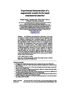
oscilloscope (RIGOL MSO4054) for further offline signal processing in order to recover the transmitted data. Note that, all the key system parameters adopted in this work are depicted in Table I. Fig. 4 illustrates the BER performance as a function of the data rate for NOMA-OFDM and NOMA-SCFDM schemes. Each BER point is determined based on the average of the two users for a date stream of 1 × 105 bits long. Note that, the NOMA power allocated ratios (PARs) are both 0.25, which is considered as the optimum power allocation ratio. However, the PAPR are ~13 dB and ~12 dB for NOMA-OFDM and NOMA-SCFDM, respectively. As shown in Fig. 4, NOMA-SCFDM offers improved BER performance compared to NOMA-OFDM due to its low PAPR. For example, at a BER of 10-3 (forward error correction limit) the increase in the data rate is ~ 2 Mb when using NOMA-SCFDM compared to NOMA-OFDM. At BERs lower than 10-3 both system deliver almost the same data rate. Also shown in Fig. 4 are the constellation diagrams for both schemes at a data rate of 17.86 Mbps, which confirms enhanced performance of NOMA-SCFDM. Finally, we investigate the BER performance against the data rate for NOMA-SCFDM for two users as shown in Fig. 5. Note that, at the Tx the user 1 is allocated with higher power than the user 2, and at the Rx the data of the user 1 is decoded prior to that a of the user 2. In order to recover the data for the user with no error, it is essential that data recovery for the user 1 is performed accurately with lower BER. Thus, as shown in Fig. 5 for a given data rate the BER performance for the user 1 is lower than the user 2. 5. Conclusion We proposed and experimentally demonstrated a NOMA-SCFDM scheme for downlink VLC transmission, which provided lower PAPR, a good balance between throughput and fairness and a higher system capacity for a larger number of users compared to the NOMA-OFDM. The transmission performances of NOMA-OFDM and NOMA-SCFDM were compared. The experiment results showed that for a given data rates NOMA-SCFDM offered improved BER performance compared to NOMA-OFDM over a propagation distance of up to 2 m. Acknowledgement This work was supported by Chunmiao Project of Haixi Institutes, CAS, National Science Foundation of China under Grants 61501427, 61571128 and 61601439, External Cooperation Program of CAS under Grant 121835KYSB20160006, External Cooperation Program of Fujian Provincial Department of Science & Technology under Grant 2017I01010012, Fujian Science Foundation under Grant 2017J05111, Program of Quanzhou Science and Technology under Grant 2016G007 and Grant 2016T010. Reference [1] M. Shafi et al., "5G: A Tutorial Overview of Standards, Trials, Challenges, Deployment, and Practice," in IEEE Journal on Selected Areas in Communications, vol. 35, no. 6, pp. 1201-1221, June 2017. [2] T. S. Rappaport, G. R. Maccartney, M. K. Samimi, and S. Sun, “Wideband millimeter-wave propagation measurements and channel models for future wireless communication system design,” IEEE Trans. Commun., vol. 63, no. 9, pp. 3029–3056, Sep. 2015. [3] Ghassemlooy, Z., Alves, L. N., Zvanovec, S., and Khalighi, M-A.: Visible Light Communications: Theory and Applications, CRC June 2017, ISBN 9781498767538 [4] Jovicic, A., J. Li, and T. Richardson. "Visible light communication: opportunities, challenges and the path to market." IEEE Communications Magazine, vol. 5, no.12, pp. 26-32, 2013. [5] Bangjiang Lin, Xuan Tang, Zabih Ghassemlooy, Xi Fang, Chun Lin, Yiwei Li, Shihao Zhang, “Experimental Demonstration of OFDM/OQAM Transmission for Visible Light Communications”, IEEE Photonics Journal, vol. 8, no. 5, pp. 7906710, 2016. [6] Bangjiang Lin, Xuan Tang, Zabih Ghassemlooy, Shihao Zhang, Yiwei Li, “Efficient Frequency Domain Channel Equalization Methods for OFDM Visible Light Communications ” , IET Communication, 2017, 11 (1): 25-29. [7] D. Bykhovsky and S. Arnon, “Multiple Access Resource Allocation in Visible Light
Communication Systems”, IEEE J. of Lightwave Techn., 32 (8), pp. 1594-1600, 15 March 2014. [8] Zhong Zheng, Te Chen, Lu Liu, Weiwei Hu. “Experimental Demonstration of Femtocell Visible Light Communication System Employing Code Division Multiple Access”, in Proc. OFC Conf., Mar. 22–26, 2015, pp. Tu2G.4. [9] Bangjiang Lin, Xuan Tang, Hui Yang, Zabih Ghassemlooy, Shihao Zhang, Yiwei Li, and Chun Lin, “Experimental Demonstration of IFDMA for Uplink Visible Light Communication”, IEEE Photonics Technology Letters, vol.28, no.20, pp.2218-2220, 2016. [10] Bangjiang Lin, Weiping Ye, Xuan Tang, and Zabih Ghassemlooy, “Experimental Demonstration of Interleave Division Multiple Access Visible Light Communication”, Optical Engineering, 2017, 56(5):056101. [11] M. Guerra-Medina, B. Rojas-Guillama, O. Gonzalez, J. Martin-Gonzalez, E. Poves, and F. Lopez-Hernandez, “Experimental optical code-division multiple access system for visible light communications,” in Proc. Wireless Telecommun. Symp., 2011, pp. 1–6. [12] Y. Saito, et al, “Non-orthogonal multiple access (NOMA) for future radio access,” in Proc. IEEE Vehiccular Technology Conference (VTC Spring), 2013, pp. 1-5. [13] Dai, Linglong, et al. "Non-orthogonal multiple access for 5G: solutions, challenges, opportunities, and future research trends." Communications Magazine IEEE 53 (9), 74-81 (2015). [14] Z. Ding, Z. Yang, P. Fan, and H. Poor, “On the performance of nonorthogonal multiple access in 5G systems with randomly deployed users,” IEEE Signal Process. Lett. 21 (12), 1501–1505 (2014). [15] Z. Ding, Z. Yang, P. Fan, and H. Poor, “On the performance of nonorthogonal multiple access in 5G systems with randomly deployed users,” IEEE Signal Process. Lett., vol. 21, no. 12, pp. 1501– 1505, Dec. 2014. [16] H Marshoud, VM Kapinas, GK Karagiannidis, S Muhaidat, “Non-Orthogonal Multiple Access for Visible Light Communications,” IEEE Photonics Technology Letters, 28 (1), 51-54 (2016). [17] RC Kizilirmak, CR Rowell, M Uysal, “Non-orthogonal multiple access (NOMA) for indoor visible light communications,” IEEE International Workshop on Optical Wireless Communications, 2015, pp. 98–10. [18] Yin, Liang, X. Wu, and H. Haas. “On the performance of non-orthogonal multiple access in visible light communication,” IEEE International Symposium on Personal, Indoor, and Mobile Radio Communications, 2015, pp. 1354–1359. [19] Xun Guan, Qing Yang, Yang Hong, and Calvin Chun-Kit Chan, "Non-orthogonal multiple access with phase pre-distortion in visible light communication," Optics Express, 24 (22), 25816-25823 (2016). [20] Bangjiang Lin, Weiping Ye, Xuan Tang and Zabih Ghassemlooy, “Experimental demonstration of bidirectional NOMA-OFDMA visible light communications”, Optics Express, vol. 25, no. 4, pp. 7-15. [21] H. Marshoud, P. C. Sofotasios, S. Muhaidat, G. K. Karagiannidis and B. S. Sharif, "Error performance of NOMA VLC systems," 2017 IEEE International Conference on Communications (ICC), Paris, 2017, pp. 1-6. [22] Z. Cheng et al., “Experimental demonstration of a single-carrier frequency division multiple address based PON (SCFDMA-PON) architecture,” Opt. Express 18(24), 24556–24564 (2010). [23] Bangjiang Lin, Juhao Li, Hui Yang, Yuanbao Luo, Yangsha Wan, Yongqi He, Zhangyaun Chen,” Direct Detection SCFDE for Passive Optical Network Based on TDM and Polarization Interleaving”, OptoElectronics and Communication Conference 2014, TH12C-4. [24] Yuanxiang Chen, Juhao Li, Paikun Zhu, Yingying Xu, Yongqi He, Zhangyuan Chen, “Experimental Demonstration of 1.2-Tb/s Optical PDM SCFDM Superchannel Multicasting by HNLF” IEEE Photonics Journal, 5(5), 7902007, 2014. [25] J. G. Proakis, Digital Communications, 4th ed., ser. McGraw-Hill Series in Electrical and Computer Engineering, S. W. Director, Ed. McGraw-Hill Higher Education, December 2000. Figures Fig. 1 System block diagrams for transmitter: (a) OFDM, and (b) SCFDM; and receiver: and (d) SCFDM.
(c) OFDM,
S / P
QAM Modulation
d(t)
Subcarrier Mapping
P / S
Add CP/ Preamble
IDFT
(a) S / P
QAM Modulation
d(t)
DFT
Subcarrier Mapping
P / S
Add CP/ Preamble
IDFT
(b) S / P
Remove CP
Channel Equalization
DFT
P / S
QAM Demodulation
data
(c) S / P
Remove CP
Channel Equalization
DFT
IDFT
QAM Demodulation
P / S
data
(d)
Fig. 2 Block diagram of downlink NOMA-OFDM/SCFDM VLC. s1 P1 User 1 Source x1 Power OFDM/SCFDM Allocation Modulation Data s + t DAC s N x ...
Add DC
User N Source
N
Data
xˆ1
xˆ2
PN
LED P
y OFDM/SCFDM Demodulation
OFDM/SCFDM Demodulation
Frame Synchronization
hlos p1 xˆ1
ADC
Optical Rx
Lens
Free Space Optical Channel
-
...
xˆ N
Power Allocation
OFDM/SCFDM Modulation
-
hlos pN 1 xˆ N 1
OFDM/SCFDM Demodulation
Fig. 3 Experimental setup for the downlink NOMA-VLC. Matlab Matlab NOMA-OFDM/ SCFDM Coder
NOMA-OFDM/ SCFDM Decoder
Arbitrary Waveform Generator
Scope LED Transmitter
DC supply Bias Tee
st
i 1 / 2
d
i
Op tica Lens Rx l
y
Fig. 4 BER performance vs. the data rate for the downlink VLC for NOMA-OFDM and NOMA-SCFDM.
Fig. 5 BER performance against the data rate for two users for the downlink NOMA-SCFDM.
Tables Table I. Key system parameters Parameter LED Bandwidth Semi-angle of half power Transmit power Channel span Optical Rx Wavelength range PD Active area PD Responsivity @ =970 nm Bandwidth PD Field of view Noise equivalent power at 0 dB gain OFDM/SCFDM DFT CP Modulation format Propagation distance
Value < 5 MHz ~ 60o 150 mw 2m 350-110 nm 13 mm2 < 0.6 A/W 10 MHz ~90 o 2.91 × 10⁻¹¹ W/Hz0.5 256 8 QPSK 2m