IEEE PHOTONICS TECHNOLOGY LETTERS, VOL. 24, NO. 9, MAY 1, 2012
721
Experimental Demonstration of an Elastic Packet Routing Node Based on OCDMA Label Coding Houssem Brahmi, Giannis Giannoulis, Mourad Menif, Vasilis Katopodis, Dimitrios Kalavrouziotis, Christos Stamatiadis, Christos Kouloumentas, Hercules Avramopoulos, and Didier Erasme
Abstract— We propose and demonstrate experimentally an all-optical packet routing scheme using hybrid-wavelengthdivision multiplexing/optical-code-division multiple access labeling for 40-Gb/s nonreturn-to-zero (NRZ) data. With no electronic control, the system forwards asynchronously packets delimited by valid label and suppresses unwanted traffic. It consists of an optical flip-flop controlled by two correlators combined with a Mach–Zehnder interferometer that selects packets for each fiber output. The experimental results show optical switching operation for the optical-code gate with an extinction ratio of 16 dB between the switched and unswitched packets and a switching time below 2 ns. Error-free operation has been successfully achieved with low-power penalty for 40-Gb/s NRZ data. Index Terms— All-optical flip-flop, fiber Bragg gratings, label stripping, optical packet switching, optical-code-division multiple access.
I. I NTRODUCTION
N
EW high performance fiber technologies offers impressive capabilities to support reliable digital communications in new generation networks especially with the impressive growth in Internet based traffic. Meanwhile, switching packet directly in optical domain is further required to rapidly process huge amounts of data and match transmission speed offered by the fiber optic. In recent years, the advances made in designing all-optical signal processing gates, namely all-optical flip-flops (AOFF), have helped defining the basic functions required for packet-switched architectures [1]. All-optical packet-switching involves three main functionalities: separating routinginformation from the payload, optically recognizing and processing the header and finally forwarding the packets in the optical domain to their predetermined destination. Various
Manuscript received October 7, 2011; revised December 23, 2011; accepted January 24, 2012. Date of publication February 10, 2012; date of current version April 4, 2012. This work was supported in part by BONE and EUROFOS, Networks of Excellence, and in part by the European Commission through the 7th ICT-Framework Programme. H. Brahmi is with Institut Telecom/Telecom ParisTech, CNRS UMR, Paris 5141-75634, France, and also with the High School of Communication of Tunis (Sup’Com), Carthage University, Ariana 2083, Tunisia (e-mail:
[email protected]). G. Giannoulis, V. Katopodis, D. Kalavrouziotis, C. Stamatiadis, C. Kouloumentas, and H. Avramopoulos are with the National Technical University of Athens, Athens GR 15773, Greece (e-mail:
[email protected]). M. Menif is with Sup’Com, Tunisia, Carthage University, Ariana 2083, Tunisia (e-mail:
[email protected]). D. Erasme is with Institut Telecom/Telecom ParisTech, CNRS UMR, Paris 5141-75634, France (e-mail:
[email protected]). Color versions of one or more of the figures in this letter are available online at http://ieeexplore.ieee.org. Digital Object Identifier 10.1109/LPT.2012.2187047
label recognition modules have been proposed in literature for packet-switched architectures. The Optical-code-division multiple access (OCDMA) technique, known for its suggestion of use in multiple access network, is one of promising candidate for transporting the addressing information in next generation packet-switched networks [2]. It allows the share of time and wavelength domains from several users, other dimensions such as phase and polarization can be also used to reduce the code length and/or the used bandwidth [3]. With OCDMA labeling, the routing information is carried by scrambling the label with a specific CDM code, which may be viewed as a local address. Here, the proposed packet-switched architecture offers the capability to accommodate elastic traffic across the network, with multi-rate and variable length packets using OCDMA coded label. The whole mechanism is achieved in optical domain and automatically without any external electrical control. The scheme relies on duplicating and selecting packets over an array of optical-code (OC) gates. Within each one, the label recognition stage delivers two pulses in order to control the forwarding block when header and trailer match the OCDMA code. In this letter, we demonstrate experimentally the proposed scheme of the OC-gate operating at an NRZ payload bit rate of 40 Gbit/s and label signal at 1 Gbit/s. The measurements show an error free switching operation. II. L ABELING T ECHNIQUE AND S WITCHING C ONCEPT The spectral addressing space is split into two distinct spectral bands. The payload is settled in the first band whereas the remaining spectrum is used for transmission of label addresses/codes. WDM/OCDMA labeling consist in combining WDM to OCDMA to get higher spectral efficiency and provide higher user capacity [4]. We assign each Node address to a unique optical code using the temporal encoding technique: Direct-Sequence OCDMA. The code sequences can be reused on every WDM channel of label’s band. The higher number of wavelengths is, the lower is the number of timechips required. This is an important factor for the header/trailer data rate determination [2]. This labeling technique allows an easy extraction and processing of label frame since the treatment of labels is done independently within distinct channels. Thus an easy all-optical control of the forwarding block is possible with a separate on-the-fly label recognition. The label pulse encoding is performed in time-domain using the Extended Congruent Code (EQC), used for its good correlation properties [3].
1041–1135/$31.00 © 2012 IEEE
722
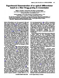
Fig. 1.
IEEE PHOTONICS TECHNOLOGY LETTERS, VOL. 24, NO. 9, MAY 1, 2012
Operating principle of optical-code gate.
The network data packet is encapsulated into a variablelength frame. This frame is constructed by adding a header in front of the payload and a trailer at the end. Header and trailer consist of a stack of many levels used to encode the route of a path, so at every hop the pertinent router strips off the top label and determines the next hop. The optical router consists of a number of OC-gates, each one being connected to an output. Its principle relies on splitting the incoming packet flow over all OC-gates, identifying OCDMA-coded label and selecting packets accordingly to be routed towards the corresponding output. At the input of the router, we extract the top of the label stack carrying the local routing information. The label extraction could be easily achieved with fiber Bragg gratings or an arrayed waveguide grating demultiplexer. Fig. 1 shows the schematic of the OC-gate. The data flows (1 to 9) illustrate the temporal evolution of packets components and control signals at several points of the system. Every OC-gate is associated to two distinct and unique OCDMA codes. Guard-times are introduced either between the signaling and the payload part or between the adjacent levels of header/trailer, satisfying thereby the gate’s specifications and facilitating the label extraction. The label recognition block involves optical correlators using structured fiber Bragg gratings (S-FBG) decoders that compare the incoming packet identification to a predetermined label code. OCDMA decoders generate two correlation pulses delimiting the packet payload and controlling the AOFF. Only the autocorrelation pulse of the matched codes exhibits the power level that is suitable for AOFF triggering. The ON/OFF output of the AOFF as well as the payload acts as input signals for the MZI-based AND-gate and using Cross Phase Modulation (XPM) effect in SOAs. Thus, the packet payload can be forwarded when the AOFF is activated and blocked otherwise. III. E XPERIMENT AND R ESULTS Fig. 2 shows the experimental setup used to demonstrate the packet-switching node. It includes: the 40 Gb/s optical payload generator, the optical label generator, the all-optical recognition unit, the forwarding block and the evaluation stage. The experimental study of the proposed concept was confirmed by using a common pair of coder, decoder for both packet’s header and trailer coding. This modification facilitates the experimental validation, preserving at the same time the concept’s elastic potentiality for packets with variable length. Two packets are launched successively, the first one being delimited by valid coded labels (100000100010000) as
Fig. 2.
Experimental setup.
previously mentioned synchronized with the ON state of the flip-flop, whereas the second is delimited by invalid coded labels (100000010010000), unable to activate the AOFF and thus synchronized with the OFF state. The payload generator block delivers the payload. It employs a CW source emitting at 1559.08nm. A first Pulse Pattern Generator (PPG) generates a (27 − 1) pseudo-random binary sequence (PRBS) at 40 Gb/s to form the non-return-tozero payloads (1500 bits for the first packet and 1000 bits for the second). The provided electrical data packets are used as the driving signal in order to modulate an optical Return-to-Zero (RZ) pulse train with a Ti:LinbO3 modulator which is fully synchronous with the PPG. The second modulator is used to obtain the desirable packet formatting. The synchronization of the data with the labels is adjusted with a tunable delay line (ODL3). The durations of packet1 and packet2 are fixed to 37.5 ns and 25 ns respectively while the repetition period is fixed to 234 ns. The payload flow is shown in fig. 3(d). The label generation block provides OCDMA-coded headers and trailers. It employs a tunable CW source emitting at 1549.8nm which is then directed to an electro-absorption modulator (EAM) driven by a 12GHz clock signal and yielding in a 50ps RZ pulse-train which satisfies the coders specifications. A pulse generator tunes the pulse repetition rate to those of packets flow. The resulting signal is amplified using an EDFA then divided to be encoded separately by S-FBG1 and S-FBG2. The coding of the two packet labels is performed with EQC (p = 3) codes: C1 for the first packet and C2 for the second one. The temporal response of coder C1 is depicted in fig. 3(a). A detailed characterization of these codes can be found in [3]. A time delay around 120ns (ODL1) between the two packets is induced by adding a fiber delay line in the second packet path. The coded labels are then recombined and directed to the label recognition unit of the OC-gate.
BRAHMI et al.: EXPERIMENTAL DEMONSTRATION OF AN ELASTIC PACKET ROUTING NODE
723
Fig. 3. (a) Temporal response of label coder 1. (b) Label1 decoded (autocorrelation pulse). (c) Decoded label after broadening. (d) Transmitted packet flow. (e) Flip-flop output. (f) Forwarded packet flow. (g) BER measurement: i) back-to-back data and ii) switched data.
In the present implementation, the gate selects packet carrying C1 labels to be forwarded to its output, the label recognition block is essentially composed of a S-FBG decoder D1 that produces correlation signal of OCDMA label and code C1 (cf. fig. 3(b)). With a valid code, the autocorrelation pulse width is around 50 ps whereas the required width of Set and Reset pulses must be at least 150 ps to be able to control the AOFF. Temporal pulse broadening is required to get suitable control signals for the forwarding unit. This operation is realized by means of a Fabry-Perot Filter with Free Spectra Range (FSR) equal to 10.1 GHZ and a Finesse of 100.4 that broadens the pulse up-to a width of 250-to-400ps. The extinction ratio of the broadened pulses was found to be around 8.4 dB. After the amplification, the pulse is split into set and reset pulses. By employing a common valid code for both header and trailer, the delay line (ODL2) was used to generate an approximate delay of 46 ns between the Set and Reset pulses that is equal to the packet1 duration. Signals are launched into the AOFF through a polarization controller (PC) and an isolator. Signal powers are tunned with attenuators. The forwarding unit utilizes an integrated InP/InGaAsP AOFF (Detailed description can be found in [5]) coupled to a SOA-MZI based optical AND. The validation starts with the evaluation of the AOFF performance without data traffic. The Set/Reset pulses and the AOFF response are shown in figs 3(c) and 3(d) respectively. The latching operation was demonstrated with controlling signal produced with EQC (p=3) coders. Other codes such as Quadratic Congruence (p=5) codes was also tested. The two AOFF CW bias, set and reset powers are 10, 4.96, −10.3 and −12.42 dBm respectively. An output contrast ratio of 11 dB is obtained with a minimum rise-time of 1.67 ns and fall-time of 1.74 ns. These short response times allow the processing of packet-flows with short inter-packet delay and short timeguard between payload and headers/trailers. However, in this experiment, we preferred a longer guard-time in order to easily perform the signal’s synchronization and since we mainly focus on the switching performance evaluation of the system. The next step is to demonstrate the forwarding operation under real traffic conditions while the SOA-MZI-based AND gate is controlled by the AOFF output. The used SOA-MZI presents an extinction ratio of 30 dB between switched and unswitched ports with bias currents of I1 = 303 mA and I2 = 297 mA. Fig. 3(f) shows the first packet, which is correctly forwarded, while the second one was totally
suppressed resulting in an extinction ration of around 16 dB. A clear eye-diagram of the forwarded packet is shown in ii) of fig. 3(g), as compare to the back-to-back in i) of fig. 3(g). For the bit-error-rate (BER), the 40 Gb/s packets are electrically time de-multiplexed at the output in order to get 10 Gb/s tributaries allowing burst bit-error-rate measurement using our equipment. Fig. 3(g) shows BER measurements obtained at the output of the proposed scheme. Curves are plotted using the received power measured before electrical detection and demulteplexing (4X tributary power). Each BER curve corresponds to the worst performing tributary, which are associated with the 40 Gb/s signal. Error free operation with power penalty of less than 2 dB was achieved for the output packet. This low power penalty is obtained thanks to the high extinction ratio of the MZI that reshape the signal and enhance its quality. This offers a high cascadability of OC-gates and thus scalable network. IV. C ONCLUSION We present experimental demonstration of an all-optical packet-switched network using Optical Code Division Multiplexing technology able to switch the data without passing through an electrical conversion for any packet length and independently of bit rate. The optical router is based on an array of Optical Code gates, where each gate is filtering packets to be routed towards a predetermined router output. OC gate is composed by an AOFF controlled by two OCDMA decoders and an SOA-MZI. ACKNOWLEDGMENT The authors would like to thank TU/e University, Eindhoven, The Netherlands, for lending them the flip-flop device. R EFERENCES [1] H. Brahmi, et al., “Experimental demonstration of an all-optical packet forwarding gate based on a single SOA-MZI at 40 Gb/s,” in Proc. IEEE OFC, Los Angelos, CA, Mar. 2011, pp. 1–3. [2] A. Teixeira, et al., “All-optical routing based on OCDMA headers,” in Proc. IEEE LEOS, Oct. 2004, pp. 1046–1047. [3] I. Fsaifes, C. Lepers, A.-F. Obaton, and P. Gallion “DS-OCDMA encoder/decoder performance analysis using optical low-coherence reflectometry,” J. Lightw. Technol., vol. 24, no. 8, pp. 3121–3128, Aug. 2006. [4] X. Wang, N. Wada, T. Miyazaki, G. Cincotti, and K. I. Kitayama, “Hybrid WDM/OCDMA for next generation access network,” Proc. SPIE, vol. 6783, pp. 678328-1–678328-14, Nov. 2007. [5] Y. Liu, et al., “Characterization of hybrid integrated all-optical flip-flop,” in Proc. IEEE LEOS, Montreal, Canada, Oct. 2008, pp. 943–944.