Experimental demonstration of polarization encoding quantum key distribution system based on intrinsically stable polarization-modulated units Jindong Wang,1,* Xiaojuan Qin,2 Yinzhu Jiang,1 Xiaojing Wang,1 Liwei Chen,2 Feng Zhao,3 Zhengjun Wei,1 and Zhiming Zhang1 1
Guangdong Provincial Key Laboratory of Nanophotonic Functional Materials and Devices, Guangdong Provincial Key Laboratory of Quantum Engineering and Quantum Materials, South China Normal University, Outer Ring Road, High Education City, Guangzhou, 510006, China 2 Guangdong Polytechnic Institute, Tong Xin Road, Guangzhou 510091, China 3 School of Physics and Telecommunication Engineering, Shanxi University of Technology, Chao Yang Road, Hanzhong 723000, China *
[email protected]
Abstract: A proof-of-principle demonstration of a one-way polarization encoding quantum key distribution (QKD) system is demonstrated. This approach can automatically compensate for birefringence and phase drift. This is achieved by constructing intrinsically stable polarization-modulated units (PMUs) to perform the encoding and decoding, which can be used with four-state protocol, six-state protocol, and the measurement-deviceindependent (MDI) scheme. A polarization extinction ratio of about 30 dB was maintained for several hours over a 50 km optical fiber without any adjustments to our setup, which evidences its potential for use in practical applications. ©2016 Optical Society of America OCIS codes: (270.5568) Quantum cryptography; (060.4510) Optical communications; (250.4110) Modulators; (230.5440) Polarization-selective devices.
References and links 1. 2. 3. 4. 5. 6.
7. 8. 9.
C. H. Bennet and G. Brassard, “Quantum cryptography: Public key distribution and coin tossing,” in Proceedings of IEEE International Conference on Computers, Systems and Signal Processing (Institute of Electrical and Electronics Engineers, Bangalore, India, 1984), pp. 175–179. C. H. Bennett, “Quantum cryptography using any two nonorthogonal states,” Phys. Rev. Lett. 68(21), 3121– 3124 (1992). C. Kurtsiefer, P. Zarda, M. Halder, H. Weinfurter, P. M. Gorman, P. R. Tapster, and J. G. Rarity, “Quantum cryptography: a step towards global key distribution,” Nature 419(6906), 450 (2002). D. Stucki, N. Gisin, O. Guinnard, G. Ribordy, and H. Zbinden, “Quantum key distribution over 67km with a plug&play system,” New J. Phys. 4, 41 (2002). Y. Liu, T.-Y. Chen, J. Wang, W. Q. Cai, X. Wan, L. K. Chen, J. H. Wang, S. B. Liu, H. Liang, L. Yang, C. Z. Peng, K. Chen, Z. B. Chen, and J. W. Pan, “Decoy-state quantum key distribution with polarized photons over 200 km,” Opt. Express 18(8), 8587–8594 (2010). M. Sasaki, M. Fujiwara, H. Ishizuka, W. Klaus, K. Wakui, M. Takeoka, S. Miki, T. Yamashita, Z. Wang, A. Tanaka, K. Yoshino, Y. Nambu, S. Takahashi, A. Tajima, A. Tomita, T. Domeki, T. Hasegawa, Y. Sakai, H. Kobayashi, T. Asai, K. Shimizu, T. Tokura, T. Tsurumaru, M. Matsui, T. Honjo, K. Tamaki, H. Takesue, Y. Tokura, J. F. Dynes, A. R. Dixon, A. W. Sharpe, Z. L. Yuan, A. J. Shields, S. Uchikoga, M. Legré, S. Robyr, P. Trinkler, L. Monat, J. B. Page, G. Ribordy, A. Poppe, A. Allacher, O. Maurhart, T. Länger, M. Peev, and A. Zeilinger, “Field test of quantum key distribution in the Tokyo QKD Network,” Opt. Express 19(11), 10387– 10409 (2011). T. Scheidl, R. Ursin, A. Fedrizzi, S. Ramelow, X. S. Ma, T. Herbst, R. Prevedel, L. Ratschbacher, J. Kofler, T. Jennewein, and A. Zeilinger, “Feasibility of 300 km quantum key distribiton with entangled states,” New J. Phys. 11(8), 085002 (2009). H. Takesue, T. Sasaki, K. Tamaki, and M. Koashi, “Experimental quantum key distribution without monitoring signal disturbance,” Nat. Photonics 9(12), 827–831 (2015). S. Wang, Z. Q. Yin, W. Chen, D. Y. He, X. T. Song, H. W. Li, L. J. Zhang, Z. Zhou, G. C. Guo, and Z. F. Han, “Experimental demonstration of a quantum key distribution without signal disturbance monitoring,” Nat. Photonics 9(12), 832–836 (2015).
#260235 © 2016 OSA
Received 29 Feb 2016; revised 3 Apr 2016; accepted 4 Apr 2016; published 8 Apr 2016 18 Apr 2016 | Vol. 24, No. 8 | DOI:10.1364/OE.24.008302 | OPTICS EXPRESS 8302
10. S. Wang, W. Chen, Z. Q. Yin, H. W. Li, D. Y. He, Y. H. Li, Z. Zhou, X. T. Song, F. Y. Li, D. Wang, H. Chen, Y. G. Han, J. Z. Huang, J. F. Guo, P. L. Hao, M. Li, C. M. Zhang, D. Liu, W. Y. Liang, C. H. Miao, P. Wu, G. C. Guo, and Z. F. Han, “Field and long-term demonstration of a wide area quantum key distribution network,” Opt. Express 22(18), 21739–21756 (2014). 11. S. Wang, W. Chen, J. F. Guo, Z. Q. Yin, H. W. Li, Z. Zhou, G. C. Guo, and Z. F. Han, “2 GHz clock quantum key distribution over 260 km of standard telecom fiber,” Opt. Lett. 37(6), 1008–1010 (2012). 12. S. Wang, W. Chen, Z. Q. Yin, Y. Zhang, T. Zhang, H. W. Li, F. X. Xu, Z. Zhou, Y. Yang, D. J. Huang, L. J. Zhang, F. Y. Li, D. Liu, Y. G. Wang, G. C. Guo, and Z. F. Han, “Field test of wavelength-saving quantum key distribution network,” Opt. Lett. 35(14), 2454–2456 (2010). 13. J. Chen, G. Wu, L. Xu, X. Gu, E. Wu, and H. Zeng, “Stable quantum key distribution with active polarization control based on time-division multiplexing,” New J. Phys. 11(6), 065004 (2009). 14. I. Lucio-Martinez, P. Chan, X. Mo, S. Hosier, and W. Tittel, “Proof-of-concept of real-world quantum key distribution with quantum frames,” New J. Phys. 11(9), 095001 (2009). 15. W.-Y. Liang, S. Wang, H.-W. Li, Z.-Q. Yin, W. Chen, Y. Yao, J.-Z. Huang, G.-C. Guo, and Z.-F. Han, “Proofof-principle experiment of reference-frame-independent quantum key distribution with phase coding,” Sci. Rep. 4(3617), 3617 (2014). 16. A. Laing, V. Scarani, J. G. Rarity, and J. L. O’Brien, “Reference-frame-independent quantum key distribution,” Phys. Rev. A 82(1), 012304 (2010). 17. C. Wang, X. T. Song, Z. Q. Yin, S. Wang, W. Chen, C. M. Zhang, G. C. Guo, and Z. F. Han, “Phase-referencefree experiment of measure-device-dependent quantum key distribution,” Phys. Rev. Lett. 115(16), 160502 (2015). 18. S. Nauerth, M. Fürst, T. Schmitt-Manderbach, H. Weier, and H. Weinfurter, “Information leakage via side channels in freespace BB84 quantum cryptography,” New J. Phys. 11(6), 065001 (2009). 19. Y. S. Kim, Y. C. Jeong, and Y. H. Kim, “Implementation of polarization-coded free-space BB84 quantum key distribution,” Laser Phys. 18(6), 810–814 (2008). 20. X. B. Liu, C. H. Liao, J. L. Mi, J. D. Wang, and S. H. Liu, “Intrinsically stable phase-modulated polarization encoding system for quantum key distribution,” Phys. Lett. A 54, 373 (2008). 21. X. B. Liu, C. H. Liao, Z. L. Tang, J. D. Wang, Z. J. Wei, and S. H. Liu, “Polarization coding and decoding by phase modulation in polarizing sagnac interferometers,” Proc. SPIE 6827, 68270I (2007). 22. C. Gobby, Z. L. Yuan, and A. J. Shields, “Quantum key distribution over 122km of standard telecom fiber,” Appl. Phys. Lett. 84(19), 3762 (2004). 23. P. D. Townsend, “Quantum cryptography on optical fiber networks,” Proc. SPIE 3385, 2–13 (1998). 24. X. F. Mo, B. Zhu, Z. F. Han, Y. Z. Gui, and G. C. Guo, “Faraday-Michelson system for quantum cryptography,” Opt. Lett. 30(19), 2632–2634 (2005). 25. H. Q. Ma, J. L. Zhao, and L. A. Wu, “Quantum key distribution based on phase encoding and polarization measurement,” Opt. Lett. 32(6), 698–700 (2007). 26. X. B. Liu, C. H. Liao, Z. L. Tang, J. D. Wang, and S. H. Liu, “Quantum key distribution system with six polarization states encoded by phase modulation,” Chin. Phys. Lett. 25(11), 3856–3859 (2008). 27. H. W. Li, S. Wang, J. Z. Huang, W. Chen, Z. Q. Yin, F. Y. Li, Z. Zhou, D. Liu, Y. Zhang, G. C. Guo, W. S. Bao, and Z. F. Han, “Attacking a practical quantum-key-distribution system with wavelength-dependent beam-splitter and multiwavelength sources,” Phys. Rev. A 84(6), 062308 (2011). 28. J. Snoddy, Y. Li, F. Ravet, and X. Bao, “Stabilization of electro-optic modulator bias voltage drift using a lockin amplifier and a proportional-integral-derivative controller in a distributed Brillouin sensor system,” Appl. Opt. 46(9), 1482–1485 (2007). 29. H. Kawakami, E. Yoshida, and Y. Miyamoto, “Auto bias control technique based on asymmetric bias dithering for optical QPSK modulation,” J. Lightwave Technol. 30(7), 962–968 (2012). 30. H.-K. Lo, M. Curty, and B. Qi, “Measurement-device-independent quantum key distribution,” Phys. Rev. Lett. 108(13), 130503 (2012). 31. Y. Liu, T.-Y. Chen, L.-J. Wang, H. Liang, G.-L. Shentu, J. Wang, K. Cui, H.-L. Yin, N.-L. Liu, L. Li, X. Ma, J. S. Pelc, M. M. Fejer, C.-Z. Peng, Q. Zhang, and J.-W. Pan, “Experimental measurement-device-independent quantum key distribution,” Phys. Rev. Lett. 111(13), 130502 (2013). 32. Z. Tang, Z. Liao, F. Xu, B. Qi, L. Qian, and H.-K. Lo, “Experimental demonstration of polarization encoding measurement-device-independent quantum key distribution,” Phys. Rev. Lett. 112(19), 190503 (2014).
1. Introduction The science of quantum cryptography (QC) or quantum key distribution (QKD) offers new methods of secure communication and could well be the first practical application of quantum information at the single-quantum level. Since the classic “BB84” protocol was first introduced and demonstrated by Bennett et al. [1,2], many schemes have been proposed to operate by a variety of protocols over optical fibers or free space [3–12]. In most QKD systems, polarization and phase encoding schemes are usually employed. Polarization encoding schemes possess unique potential for use over free space. Furthermore, feasibility over optical fibers has also been demonstrated by introducing active feedback compensation techniques [13,14] and the reference-frame-independent (RFI) protocol [15–17].
#260235 © 2016 OSA
Received 29 Feb 2016; revised 3 Apr 2016; accepted 4 Apr 2016; published 8 Apr 2016 18 Apr 2016 | Vol. 24, No. 8 | DOI:10.1364/OE.24.008302 | OPTICS EXPRESS 8303
The four-laser scheme was first proposed to demonstrate the polarization encoding QKD system, but this approach is vulnerable to side attacks from eavesdroppers [18]. Some active polarization modulators based on the magneto-optical or the electro-optical effect are also employed to produce the required polarization states [19], but these devices require highvoltage pulses to drive, and it is difficult to improve the modulation rate. Because polarization encoding is essentially a differential phase encoding between two orthogonal polarization states, some schemes based on polarization encoding via phase modulation have been introduced to realize QKD. In these polarization encoding and decoding units, the birefringence for the two separated orthogonal polarization states and the phase drift between them will make the units hard to operate stably. More elaborate schemes have been proposed to improve the stability of the units, such as the one-way polarization modulator [14], the two-way polarization modulator [14], the Faraday-Sagnac interferometer [20,21], etc. However, it is necessary to use a polarization-maintaining fiber (PMF) in these polarization modulators in order to ensure the robustness of the QKD system. Here we present a new intrinsically stable polarization-modulated unit (PMU), and demonstrate both theoretically and experimentally that it is extremely stable and feasible in QKD systems. Accordingly, the PMF is not needed in our unit, and all of the devices in the PMU are linked by the single-mode optical fibers (SMFs). We can use the new PMUs to operate with four-state protocol, six-state protocol, and the measurement-device-independent (MDI) QKD scheme by modifying the configuration of the entire QKD system. 2. System configuration of our QKD setup The setup used for communication between Alice and Bob is sketched in Fig. 1. The pulses emitted from the laser diode (LD) are first attenuated by an intensity modulator (IM) to generate decoy states, and then sent into the PMU though an optical circulator (CIR1) that allows the input and output optical pulses to be separated. The output pulses can be modulated by the PMU to create polarization states according to the adopted protocol. As an example, the polarization states for the BB84 (four-state) protocol are + 45° ( 2( ex + ey ) / 2 ), −45° ( 2( ex − ey ) / 2 ), right circular (R or 2( ex + i ey ) / 2 ), and left circular (L or
2( ex − i ey ) / 2 ), in which ex
and e y
are the two orthogonal
polarization bases.
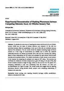
Fig. 1. Schematic of our quantum key distribution (QKD) system. LD, laser diode; IM, an intensity modulator; CIR1, CIR2, optical circulator; PBS1, PBS2, four-port polarization beam splitter; PM1, PM2, phase modulator; FM1–FM6, Faraday mirror; QC, quantum channel; PC, polarization controller; PBS3, three-port polarization beam splitter; λ/2, half-wave plate; D1, D2, single-photon detector.
The encoded single-photon pulses are transmitted to Bob’s security region through the quantum channel (QC). A polarization controller (PC) or a polarization-compensation unit (not shown) [13,14] is then used to correct for birefringence effects introduced by the QC
#260235 © 2016 OSA
Received 29 Feb 2016; revised 3 Apr 2016; accepted 4 Apr 2016; published 8 Apr 2016 18 Apr 2016 | Vol. 24, No. 8 | DOI:10.1364/OE.24.008302 | OPTICS EXPRESS 8304
[22,23]. Another optical circulator (CIR2) is also adopted to separate the input and output optical pulses. Upon arriving at Bob’s PMU, the incoming pulses are decoded and then recorded by the two single-photon detectors (SPDs, D1 and D2) after a half-wave plate and a three-port polarization beam splitter (PBS3). Finally, Bob uses a public channel to communicate to Alice the measurement basis that he used to measure each pulse, and then they establish their secret key. 2.1 The intrinsically stable polarization-modulated unit (PMU) We designed an intrinsically stable PMU to generate the polarization states for a particular protocol, which includes a four-port polarization beam splitter (PBS1), a polarizationinsensitive phase modulator (PM1), and three Faraday mirrors (FM1–FM3). Figure 2 shows the schematics of the PMU. The input polarization state is divided into two orthogonal polarization pulses, ex and e y , by PBS1. For convenience, we stipulate that PBS1 reflects (transmits) the vertically (horizontally) polarized pulse ey
( ex ). These two orthogonal
polarization pulses then travel through different paths in the PMU, and recombine at PBS1 to output in the opposite direction. At this point, PM1 is modulated at an appropriate time slot to introduce a phase shift between the two components, resulting in a polarization modulation.
Fig. 2. Schematic diagram of the proposed polarization-modulated unit (PMU). (See text for notation.)
To explain how the PMU works, we calculate the polarization evolution of light using Dirac notation: Pout = PˆPMU Pin .
(1)
Here Pout and Pin denote the polarization state of the output and input light, respectively, and PˆPMU is the polarization transformation operator of the PMU. We label the optical fiber between the four-port PBS and FMi as i (i = 1, 2, 3), and label the input port as 0. (We also label the trunk path out of PMU as 0 in the following.) To obtain the operator PˆPMU , we first provide the operator of the main components. When the pulses with a + 45° linear polarization state enter PBS1 at the 0 port, the polarization-splitting operator of PBS1 should be: PˆPBS1− 0 − in = ex , 2 ex , 0 + ey ,1 ey , 0 ,
(2)
where the operator PˆPBS 1− 0 − in represents the polarization-splitting operator of PBS1 for the input polarization pulses at the 0 port. Similarly, the polarization-splitting operators of PBS1 for the input polarization pulses at the other ports can be written as:
#260235 © 2016 OSA
Received 29 Feb 2016; revised 3 Apr 2016; accepted 4 Apr 2016; published 8 Apr 2016 18 Apr 2016 | Vol. 24, No. 8 | DOI:10.1364/OE.24.008302 | OPTICS EXPRESS 8305
PˆPBS1−1− in = ex ,3 ex ,1 + ey , 0 ey ,1 ,
(3)
PˆPBS1− 2 −in = ex , 0 ex , 2 + ey ,3 ey , 2 ,
(4)
PˆPBS1−3−in = ex ,1 ex ,3 + ey , 2 ey ,3 .
(5)
In the same way, we can express the polarization-combining operator of PBS1 as follows: PˆPBS1−1x 2 y −in = ex ,3 ex ,1 + ey ,3 e y , 2 ,
(6)
PˆPBS1−1 y 2 x −in = ey , 0 e y ,1 + ex , 0 ex , 2 ,
(7)
where PˆPBS 1−1x 2 y − in ( PˆPBS 1−1 y 2 x − in ) represents the polarization-combining operator of PBS1 when ex and ey
enter the PBS1 through fiber 1 (2) and fiber 2 (1) at the same time,
respectively. The transformation operator of the component that combines with fiber i and FMi can be expressed as follows [24,25]: PˆFMi − i = eiϕi ( ex , i ey , i + ey , i ex , i ),
(8)
where i = 1,2,3 and ϕi = ϕio + ϕie . Because the phase modulator PM1 is inserted between should be modified as: PBS1 and FM1, the operator Pˆ FM 1−1
PˆFM 1−1(t ) = ei (ϕ1 +ϕm1 (t )) ( ex ,1 ey ,1 + ey ,1 ex ,1 ),
(9)
where ϕm1(t ) is the phase shift introduced by the phase modulator PM1 while applying a control voltage. At this stage, the operator PˆPMU can be obtained by following the route in the PMU: PˆPMU = PˆPBS1−1 y 2 x −in ( PˆFM 2 − 2 + PˆFM 1−1(t 2) ) • PˆPBS 1− 3− in • PˆFM 3− 3 • PˆPBS1−1x 2 y − in • ( PˆFM 2 − 2 + PˆFM 1−1( t1) ) • PˆPBS1− 0 − in . (10)
By substituting Eqs. (2)–(9) into Eq. (10), the operator PˆPMU can be written as: i (ϕ +ϕ +ϕ +ϕ ) i (ϕ +ϕ +ϕ +ϕ ) PˆPMU = e 1 3 2 m1( t 1) ex , 0 ey , 0 + e 1 3 2 m1( t 2) ey , 0 ex , 0 .
(11)
If the input polarization state is + 45° ( Pˆin = 2( ex + ey ) / 2 ), we can obtain the output polarization state according to Eq. (1): 2 i (ϕ1 +ϕ3 +ϕ2 +ϕm1( t 1) ) 2 i (ϕ1 +ϕ3 +ϕ2 +ϕm1( t 2 ) ) e ex , 0 + e ey , 0 . (12) 2 2 Clearly, Eq. (12) shows that the output polarization state is determined by the phases of PM1 at time slots t1 and t 2 (namely, ϕm1(t1) and ϕm1(t 2) ). The influence of the birefringence and the slow phase drift of the optical fiber in the PMU can be transformed into the overall phase ( ϕm1 + ϕm 2 + ϕ m 3 ), which means that our PMU can be used to operate the polarization encoding QKD scheme extremely stably. For convenience, we cancel the overall phase Pout = PˆPMU Pin =
#260235 © 2016 OSA
Received 29 Feb 2016; revised 3 Apr 2016; accepted 4 Apr 2016; published 8 Apr 2016 18 Apr 2016 | Vol. 24, No. 8 | DOI:10.1364/OE.24.008302 | OPTICS EXPRESS 8306
ϕm1 + ϕm 2 + ϕ m3 and apply the voltage of 0 V at time slot t1 on the PM1 to obtain ϕm1(t1) = 0 . Accordingly, Eqs. (11) and (12) can be rewritten as follows: PˆPMU = ex , 0 e y , 0 + eiϕm1 e y , 0 ex , 0 , Pout = PˆPMU Pin =
2 2 iϕm1 ex , 0 + e ey , 0 . 2 2
(13) (14)
Please note that, in the above two equations, the symbol ϕ m1 directly replaces ϕm1(t 2) , which indicates the phase shift introduced by PM1 at time slot t 2 . 2.2 Encoding and decoding rules Our PMU can be used to operate the QKD scheme with both four-state and six-state protocols, and it can also be adopted to achieve a polarization encoding MDI-QKD system. As an example, we describe the encoding and decoding rules for the four-state scheme as follows. The QKD scheme based on our PMU (for operating the four-state BB84 protocol) is shown in Fig. 1. According to Eq. (14), when the four phase shifts of ϕm1 = 0, π , π , 3π are 2 2 generated at Alice’s site, the corresponding output polarization states are + 45° ( 2( ex + ey ) / 2 ), right circular (R or 2( ex + i e y ) / 2 ), −45° ( 2( ex − e y ) / 2 ) and left circular (L or
2( ex − i ey ) / 2 ), respectively.
In the same way as in Section 2.1, the polarization transform operator of the decoder for Bob can be written as: Pˆdecoder = PˆPBS 3Wˆθ PˆPMU ,
(15)
in which the operator of the half-wave plate Wˆθ (its fast axis is set at an angle of θ relative to the x-axis) should be: Wˆθ = cos 2θ ex , 0 ex , 0 + sin 2θ ex , 0 ey , 0 + sin 2θ e y , 0 ex , 0 − cos 2θ e y , 0 ey , 0 .
(16) Moreover, the operator of the three-port polarization beam splitter (PBS3) can be expressed as: PˆPBS 3 = ex , d1 ex , 0 + ey , d 2 e y , 0 ,
(17)
where d1 and d 2 are the two possible paths (spatial mode) output from PBS3. Therefore, the final form of Pˆdecoder can be simplified as: Pˆdecoder = cos 2θ ex , d1 ey , 0 + eiϕm 2 sin 2θ ex , d1 ex , 0 + sin 2θ ey , d 2 ey , 0 − eiϕm 2 cos 2θ ey , d 2 ex , 0 .
(18) According to the above equation, θ should be set as π / 8 in order to ensure that the measurement bases chosen by Bob are adopted with equal probability. From this point, Pˆdecoder can be rewritten as: Pˆdecoder =
#260235 © 2016 OSA
2 ( ex , d1 ey , 0 + eiϕm 2 ex , d1 ex , 0 + e y , d 2 ey , 0 − eiϕm 2 e y , d 2 ex , 0 ). (19) 2
Received 29 Feb 2016; revised 3 Apr 2016; accepted 4 Apr 2016; published 8 Apr 2016 18 Apr 2016 | Vol. 24, No. 8 | DOI:10.1364/OE.24.008302 | OPTICS EXPRESS 8307
It is obvious that when Bob applies a control voltage at the appropriate time slot on his phase modulator (PM2), his setup will act as the quantum decoder. The prepared polarization states of Alice and the detection probabilities of Bob for different phase values are listed in Table 1. The six-state protocol can also be operated with our PMU, whose encoder (decoder) consists of two PMUs and a half-wave plate. The operation of the six-state scheme is not elaborated on here because its basic principles and processes are described in detail in our earlier paper [26]. Table 1. The prepared polarization states and the detection probabilities for different phases according to BB84 protocol. φm1 Prepared states φm2
0 +
π/2
+
+
+
π/ 2
π
3π/ 2
D1(%)
0 10 0
50
D2(%)
0
50
0 10 0
50 50
R 0 5 0 5 0
R
π R
R
−
−
π
3π /2
0
π/ 2
0 10 0
0 10 0
π/ 2 10 0
50
0
50
3π/2 −
50
π 10 0
50
0
−
L
L
L
3π /2
0
π/ 2
π
50
50
50
50
0 10 0
L
50
3π /2 10 0
50
0
+ , 45° linear polarization; −, −45° linear polarization; R, right circular polarization; L, left circular polarization.
3. Results and discussion
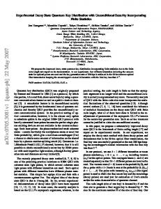
Based on our scheme, an experimental setup was built, and the performance of the setup was tested. The photons were generated by a 1550 nm pulsed laser (PDL808 Sepia, Picoquant) with a pulse width of about 70 ps. The pulses, which had a repetition frequency of 1 MHz and were polarized in the + 45° direction, were injected after attenuation into Alice’ PMU, then transmitted through the 50 km fiber spool quantum channel (QC) to Bob’s security zone. A pair of single-photon detectors (Aurea Technology, France) with a gate width of 2.5 ns and a dark count of 1 × 10⁻⁶ (ns·gate)−1 synchronized with the pulse laser was employed to test the performance of our setup. Figure 3(a) shows the photon counts of D1 and D2 versus the drive
Fig. 3. Experimental results of our setup. (a) Single-photon counts versus drive voltage on Bob’s PM2 while Alice’s PM1 remains unmodulated. (b) Variation of polarization extinction ratio over time.
voltage on Bob’s PM2, which ranged from 0 to 7.44 V, while the drive voltage on Alice’s PM1 was maintained at 0 V. A polarization extinction ratio (the maximum number of counts divided by the minimum number of counts) of about 30 dB was obtained; we were able maintain this ratio for several hours without any adjustment to our setup, as shown in Fig. 3(b). In this manner we demonstrated the feasibility of our scheme for use as a QKD system in a proof-of-principle experiment. The results are mainly affected by the extinction ratio of the optical elements and the dark count of SPD. And in our experiment, the quantum channel has
#260235 © 2016 OSA
Received 29 Feb 2016; revised 3 Apr 2016; accepted 4 Apr 2016; published 8 Apr 2016 18 Apr 2016 | Vol. 24, No. 8 | DOI:10.1364/OE.24.008302 | OPTICS EXPRESS 8308
few influences on the polarization extinction ratio, but the practical quantum key distribution need the shared reference frames for Alice and Bob. So in future key-exchange experiments, the active polarization control system [13] or RFI method [15–17] should be introduced to solve the problem of shared reference frames. One can improve the speed of the overall QKD system by employing the passive polarization decoding unit to replace the Bob’s PMU in our system, the security of the new scheme must be considered to defend the possible attacks [27]. The intrinsically stable PMUs are the essential components of our scheme. The PMUs can also be used to perform intensity modulation and generate decoy states in the manner of Ref [14]. We can place a polarizer after a PMU to perform the intensity modulation, and the mean photon number per pulse can be controlled by adjusting the drive voltage of phase modulator in PMU. Moreover, the PMU can operate the analog modulation for continuous light to generate the laser pulse. As a result of using our PMUs, the intensity extinction ratio of the output pulses was measured to reach a stable output of about 20 dB. Nevertheless, the drift of the bias voltage point remains a key technical problem [28,29] for the conventional M-Z type LiNbO3 electro-optic intensity modulator. From this perspective, our intensity modulator can remain the intensity extinction ratio without any adjustment, and possesses special advantages and promising practical applications. Recently, the MDI-QKD scheme has attracted extensive attention because it is immune to all attacks on detection [5,30,31]. In its experimental demonstration, the PMU is also used to generate the required polarization states [32], and our PMU can therefore be employed to enhance the performance of the MDI-QKD system. 4. Conclusion
We designed an intrinsically stable PMU and demonstrated (both theoretically and experimentally) a phase-modulated polarization encoding QKD scheme that utilizes the PMU. The experimental results show that our PMU can remain extremely stable, and that a high polarization extinction ratio of about 30 dB can be maintained for several hours through a fiber spool of 50 km, thereby illustrating the PMU’s potential for use in practical systems. All optical elements in our setup can be operated at Gbps rates, and work on the implementation of a high rate MDI-QKD system with our PMU that distributes a quantum key is under way. Acknowledgments
This work was supported by the National Natural Science Foundation of China (NSFC) (Grant No. 61401262), the Natural Science Foundation of Guangdong Province (Grant Nos. 2014A030310205 and 2015A030313388), and Application Technology Research and Development Projects in Guangdong Province (Grant Nos. 2014B090901016 and 2015B010128012).
#260235 © 2016 OSA
Received 29 Feb 2016; revised 3 Apr 2016; accepted 4 Apr 2016; published 8 Apr 2016 18 Apr 2016 | Vol. 24, No. 8 | DOI:10.1364/OE.24.008302 | OPTICS EXPRESS 8309