www.nature.com/scientificreports
OPEN
Experimental Demonstration of Underwater Acoustic Scattering Cancellation
received: 09 April 2015 accepted: 03 July 2015 Published: 18 August 2015
Charles A. Rohde1, Theodore P. Martin2, Matthew D. Guild1, Christopher N. Layman2, Christina J. Naify2, Michael Nicholas2, Abel L. Thangawng2, David C. Calvo2 & Gregory J. Orris2 We explore an acoustic scattering cancellation shell for buoyant hollow cylinders submersed in a water background. A thin, low-shear, elastic coating is used to cancel the monopole scattering from an air-filled, neutrally buoyant steel shell for all frequencies where the wavelength is larger than the object diameter. By design, the uncoated shell also has an effective density close to the aqueous background, independently canceling its dipole scattering. Due to the significantly reduced monopole and dipole scattering, the compliant coating results in a hollow cylindrical inclusion that is simultaneously impedance and sound speed matched to the water background. We demonstrate the proposed cancellation method with a specific case, using an array of hollow steel cylinders coated with thin silicone rubber shells. These experimental results are matched to finite element modeling predictions, confirming the scattering reduction. Additional calculations explore the optimization of the silicone coating properties. Using this approach, it is found that scattering cross-sections can be reduced by 20 dB for all wavelengths up to k0a = 0.85.
Over the past decade, metamaterial based coordinate transformation coatings have been suggested as a path toward total scattering reduction in both electromagnetic1–4 and acoustic systems5–7. These coatings guide waves around an object while minimizing the scattering interaction with the object. However, transformation-based coatings have not been demonstrated for acoustic waves in open water because the requisite material properties are difficult to achieve, particularly for coatings which are thin on the scale of the scattering object6. An alternate method to achieve scattering reduction, originally studied for electromagnetic waves as plasmonic coatings8–10 and later extended to acoustics11, is to add a coating whose material properties result in the cancellation of the most significant scattered multipole modes over a finite frequency bandwidth. To date, this form of non-resonant acoustic scattering cancellation has primarily been studied theoretically and computationally for uniform objects, such as solid stainless steel spheres and cylinders12 with one recent exception examining hollow elastic spheres13. Experimental demonstrations of this effect are rare, and have only recently been conducted for electromagnetic waves14 in solid cylindrical systems. In acoustics, experimental demonstrations have been limited to objects in air for single frequency and single incident direction cancellation shells on solid cylinders and spheres15,16 and for hollow cylinders in the zero frequency limit using pentamode shells17. Our scattering cancellation results are unique in that we experimentally demonstrate an omnidirectional acoustic scattering reduction for hollow cylindrical shells in water. Additionally, our system is comprised of a simple, low-shear, isotropic elastomer coating which is not limited to coating rigid objects, and works in water for all wavelengths greater than three times the object diameter. Acoustic scattering cancellation enables the elimination of the leading order scattering modes, mitigating the scattering in the entire region around an object in all directions. In previous work we have 1
National Research Council Research Associate Program, U.S. Naval Research Laboratory, Code 7160, Washington, DC 20375, USA. 2U.S. Naval Research Laboratory, Code 7160, 4555 Overlook Ave., Washington, DC 20375, USA. Correspondence and requests for materials should be addressed to C.A.R. (email:
[email protected])
Scientific Reports | 5:13175 | DOI: 10.1038/srep13175
1
Collection Hydrophone
24mm
www.nature.com/scientificreports/
24mm
Scan Region
y x Source Coating T
a b Air
Steel Shell
Water
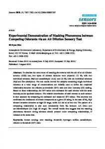
Figure 1. Experimental setup, geometry of coated shells, and image of the silicone coated array . The spherical source is located 1.1 m from sample along the x-axis, and the collection plane is vertically centered on sample. A 30 cm ruler is included for scale. The array geometry, and a single, coated, 8 mm outer diameter, stainless steel shell image is inset.
used multiple scattering theory to examine the long-wavelength effective acoustic properties of air-filled elastic cylinders and the conditions under which they become impedance matched to a water background18. However, we found that the shell thicknesses needed to meet the impedance matching condition for most common materials resulted in a density mismatch with the background medium. By contrast, in this study we start with the fixed condition that an uncoated elastic shell, with outer radius a, is density matched to the background aqueous medium through the scaling of its inner radius, b. The geometry of the coated shells and the experimental setup are illustrated in Fig. 1. An object’s dipole scattering mode is reduced to zero in the quasi-static limit when its effective density is equal to the background medium density, and the major contributor to the scattering is from the object’s effective compressibility (the monopole mode)18. We therefore introduce an elastic coating with thickness, T, that will scale the effective bulk modulus of the scatterer, while minimally impacting its effective density. To be clear, throughout we will refer to the hollow steel cylinder as a shell, the combined steel shell and air core as a hollow buoyant cylinder (HBC) and the outer compliant cylindrical shell as a coating. For a given set of material properties, the correct coating and shell thicknesses will result in the simultaneous matching of both the impedance and sound speed to the background due to the elimination of the monopole and dipole scattering modes.
Results
Formulating a broadband cancellation coating. To find the limits of the parameter space in
which our coating’s physical properties must exist, we consider the scattering properties of multilayer cylinders in a plane-wave field with wavevector magnitude k0 = 2π/λ. The monopole scattering mode of a multilayer elastic cylinder is, in general, a complicated function of its constituent component densities, bulk and shear moduli. When T ≪ a, the coating bulk modulus, κc, needed for monopole cancellation can be expressed as19,13: T
κc =
(k 0 a ) 2 a J 0 (k 0 R )
(1 − Ta ) ϒJ 0 (k0R) + k0a J1 (k0R) 1 + ρ c Ta ϒ
, (1 )
where the over-bar indicates normalization by the background medium: κ c = κ c / κ 0, ρ c is the normalized coating density, Jn is the nth order Bessel function, R = a + T is the total radius, and ϒ is a term which accounts for the finite impedance of the uncoated object13. Eq. (1) indicates the coating modulus needed to achieve monopole cancellation for any arbitrary (multilayer, anisotropic, etc.) cylindrical object at any single frequency. However, due to the non-resonant nature of the cancellation, this effect can lead to a broadband scattering reduction away from the design frequency11–13. In the quasi-static limit (k0a ≪ 1) the zeroth-order (monopole) and first-order (dipole) scattering coefficients of a multilayer cylindrical scatterer can be separated into independent respective contributions from the object’s effective bulk modulus (κeff ) and effective density (ρeff )18,20,21. Additionally, the expression for ϒ simplifies considerably13, and for a cylindrical object reduces to: Scientific Reports | 5:13175 | DOI: 10.1038/srep13175
2
www.nature.com/scientificreports/
ϒ≈−
2 1 (k 0 a ) , 2 κ
(2)
where the background normalized κ is the effective bulk modulus of the uncoated HBC. κ can be obtained from effective medium theory and can be found elsewhere22,23. For a soft rubber coating a thin metal shell, where the HBC can be approximated as an effective fluid, it follows that Eq. (1) can be replaced in the quasi-static limit by19:
κc = κ
1 − φc (κ / κeff ) − φ c
,
(3)
where φc = (a/R)2 is the shell to coating ratio. We note that monopole cancellation is achieved when κ eff = 118. From Eq. (3) it is apparent that, in the long wavelength case, the bulk modulus of the coating layer needed for monopole scattering cancellation depends only on the relative thickness of the coating, and the bulk modulus of the uncoated HBC. Also in the quasi-static limit, the normalized coating density, ρ c , which results in non-resonant dipole cancellation, is given by the volume fraction expressions19:
ρc =
ρ eff − ρφ c 1 − φc
,
(4)
where, ρ is the normalized effective density of the uncoated HBC. Similarly ρ s is the normalized effective density of the shell:
ρs =
ρ − ρ1φ s 1 − φs
,
(5)
ρ1 is the normalized density of the inner air core, and φs = (b/a)2 is the core to shell size ratio. For a fixed shell material density ρs, neutral buoyancy is set by the correct choice of shell thickness, a-b, given by Eq. (5). The sole dependence of the dipole scattering on the effective density as shown in20 ensures cancellation of the dipole scattering when ρ eff = 1. Thus, scaling the inner diameter to obtain a neutrally buoyant HBC results in the elimination of dipole scattering when ρ = ρ c = 1. With a shell thickness prescribed by Eq. (5) and a coating bulk modulus given by either Eq. (1) or (3), an air-filled, hollow scatterer can be constructed which simultaneously eliminates the scattered monopole and dipole modes. At low to moderate frequencies, this can lead to a significant reduction in the scattering strength of an object. For a submerged, neutrally buoyant shell this reduction can be observed in Fig. 2a as a function of the parameter space for the normalized coating’s physical properties at a fixed coating filling fraction, φc = 0.64 and k0a = 0.2. These values correspond to the T = 1 mm shell, coating an a = 4 mm HBC, used in our experiments at 10 kHz. Fig. 2a is a color map of the scattering cross-section ratio (σ0) of a coated HBC scatterer (σC) to an uncoated HBC scatterer (σUC) as calculated with the full scattering theory for a multilayer elastic cylinder24–26. σ0 ≡
∫ pC σC = 20 log10 S s , UC ∫ p σ UC S s
( 6)
where psi is the time averaged, scattered pressure amplitude, i = [C,UC] respectively enumerate coated/ uncoated objects, and the contour S is a closed circular path surrounding the scatterer. Near the center of Fig. 2a, the non-resonant cancellation region is observed, which is well described by Eqs. (2)–(4) for both the quasi-static (“o”) and thin shell (“x”) expressions due to our low k 0a and moderate coating thickness. Selecting coating materials with physical properties close to those given by Eqs. (2)–(4) is an important part of ensuring broadband, non-resonant cancellation. An arbitrary search of the parameter space can lead to local minima in the scattering strength, which give inherently narrow band scattering reduction (or even enhancement) due to modal anti-resonances19. These regions are labeled in Fig. 2a and are far away from our region of interest. From this analysis it can be observed that simultaneous monopole and dipole cancellation in water can be achieved using a neutrally buoyant hollow shell and a coating material with a bulk modulus below, and a density near, that of water.
Modeling a realistic coating. Compliant silicone rubbers can have a static density near water, high compressibility compared to buoyant metal shells and water, as well as a low shear modulus. In our frequency range of interest, silicone based rubbers also have a small, but non-zero, shear loss tangent which helps in damping the residual shear mode scattering. Collectively, these properties make them intriguing candidates for thin monopole cancellation coatings on metal HBC shells. In Fig. 2b we show the effective material properties for a silicone rubber coated, neutrally buoyant, stainless steel HBC Scientific Reports | 5:13175 | DOI: 10.1038/srep13175
3
www.nature.com/scientificreports/
3
0
(b)
2.5
2 1.5
Bulk Modulus (κ eff ) Density (ρeff )
1 0.5
0
0.25 0.5 0.75 Thickness Ratio (T/a)
Scattering Gain [dB]
Normalized Parameters
(a)
1
(c)
−10 −20 −30 −40 0.5
10 kHz 20 kHz 30 kHz 40 kHz 0.75 1 1.25 1.5 Coating Width [mm]
Figure 2. (a) Analytic calculation of scattering cross-section reduction of a coated neutrally buoyant stainless steel shell as a function of scaled coating parameters at fixed k0 a and φc. Non-resonant cancellation and resonant modal cancellation/enhancement regions are indicated. (b) Extracted effective bulk modulus and effective density for lossless silicone rubber coating, on a neutrally buoyant HBC, as a function of thickness, T. (c) 2D FEM calculated scattering cancellation σ0, of a neutrally buoyant, stainless steel HBC, as a function of silicone coating thickness for frequencies 10 kHz–40 kHz.
(φs = 0.88) as a function of coating thickness. These effective values were extracted from the analytic scattering theory, with no material loss. The cancellation condition is met in Fig. 2b when ρ eff = κ eff = 1. Thus, with thin shells of a commercially available silicone rubber (material properties listed in methods section) the appropriate condition for cancellation from a neutrally buoyant stainless steel shell is found to be a coating of thickness ratio T/a = 0.25. The commercial finite element method (FEM) solver COMSOL was used to explore the effects of various coating thickness on cross-section reduction for specific sample sizes. Two-dimensional (2D) FEM simulations were used to include material losses in fully elastic material components, and to model the scattering from arrays of multiple HBC scatterers. This allowed a direct comparison to our experimental results. In Fig. 2c, we plot the scattering reduction, σ0, for a coated, neutrally buoyant, steel shell (outer radius a = 4 mm) as a function of coating thickness, T, at four frequencies 10 kHz, 20 kHz, 30 kHz, and 40 kHz. Care was taken to select frequencies for which there were no intrinsic resonances in the uncoated HBC, and the contour S is a closed circular path with radius R = 150 mm. As plotted in Fig. 2c, strong (40 dB) reduction of the total scattering cross-section is seen at 10 kHz (k0a = 0.2) and continues for all frequencies below 10 kHz. This broadband reduction in scattering falls-off as we move up in frequency, but still remains significant at 40 kHz (k0a = 0.85) where the optimal coating thickness produces an 18 dB reduction in the scattered field amplitude. At frequencies larger than 40 kHz higher order modal contributions reduce the significance of the monopole cancellation. This is further elucidated in Fig. 3a,b in which scattered pressure amplitude color maps are plotted for the silicone coated HBCs at 10 kHz, 20 kHz, and for an uncoated HBC at 20 kHz in Fig. 3c. The cylinders are in water and the excitation source is a plane wave incident from the left with the amplitude normalized to the incident plane wave. The spatial distribution of the pressure amplitude strongly Scientific Reports | 5:13175 | DOI: 10.1038/srep13175
4
www.nature.com/scientificreports/
(a)
x10 (c)
x10-2 6 4 2
20kHz (b)
20kHz x10 (d)
0 90
80 60 40 20
180
10kHz
10kHz 20kHz
0
270
Figure 3. (a) 2D FEM calculated, scattered near-field pressure amplitude from silicone coated HBC with optimized thicknesses at 20 kHz (T = 1.035 mm) and (b) 10 kHz (T = 1.065 mm). (a–c) are plotted with the same color map with (a,b) scaled up by 10. (c) Scattered near-field pressure amplitude from uncoated HBC at 20 kHz and (d) angle resolved far-field sound pressure level (dB) of coated and uncoated HBC at 10 kHz (red) and 20 kHz (blue). Sound pressure level values are referenced to 1 μPa. In all cases, the outer diameters (2a) of the plotted cylinders are 8 mm.
correlates with the far-field scattering pattern plotted in Fig. 3d. In Fig. 3d the angular distribution of the far-field sound pressure level is plotted in dB for coated and uncoated HBC at 10 kHz and 20 kHz. The uncoated HBC shows a uniform (monopole) scattering, while the coated HBC at 10 kHz has a residual, quadrupole-like pattern and the coated HBC at 20 kHz has a strong dipole contribution. At 10 kHz the far-field scattering pattern is modified from a pure quadruple pattern by interaction with a weak residual dipole. The increased strength of the 20 kHz dipole scattering, while still 30 dB less than the uncoated case, is due to the increasing mismatch between the dynamic and static density of the coated HBC and the aqueous background medium.
Experimental results
The scattered pressure field of objects with k0a