Acoustical Physics, Vol. 47, No. 6, 2001, pp. 733–738. Translated from Akusticheskiœ Zhurnal, Vol. 47, No. 6, 2001, pp. 830–835. Original Russian Text Copyright © 2001 by Nazarov, Radostin, Stepanyants.
Experimental Investigation of the Self-Action of Acoustic Waves in Systems with Dissipative Nonlinearity V. E. Nazarov*, A. V. Radostin*, and Yu. A. Stepanyants** * Institute of Applied Physics, Russian Academy of Sciences, ul. Ul’yanova 46, Nizhni Novgorod, 603600 Russia e-mail:
[email protected] ** Australian Nuclear Science and Technology Organization Received October 6, 2000
Abstract—The results of experimental investigation and analytical description of the self-action of acoustic waves in a glass tube filled with dry and water saturated river sand are presented. On the basis of the analysis of experimental results, phenomenological equations of state that describe such systems are derived and the values of their parameters are determined. © 2001 MAIK “Nauka/Interperiodica”.
Experimental investigations of nonlinear acoustic effects provide the basis for revealing the mechanisms of acoustic nonlinearity of various media and for developing nonlinear methods of diagnostics of their structure and state. A promising line of investigation for solving such problems is connected with the search for media and materials, as well as with the design of systems (e.g., resonators or sound ducts), in which nonlinear effects are most conspicuous, all other factors being the same. These properties are characteristic of microinhomogeneous media (in particular, some rocks [1, 2] and metals [3]) and also of systems designed on the basis of these media. Their acoustic nonlinearity often contains both elastic (reactive) and inelastic (dissipative) components, and the inelastic nonlinearity in a number of cases significantly exceeds the elastic component. For instance, in papers [4, 5] it was found that the propagation of acoustic waves in a glass tube filled with river sand is accompanied by the effect of selfclarification, which appears as a decrease in the attenuation constant of the wave with increasing wave amplitude. The experiments described in the cited papers were carried out with dry and fully water saturated sand. For an analytical description of the self-clarification at small and large amplitudes of acoustic waves, the equation of state involving dissipative nonlinearity in the form of a power function of the strain rate was used. This paper presents the results of an extensive experimental investigation and analytical description of the effect of self-clarification in a similar system for various degrees of water saturation of sand. On the basis of the analysis of experimentally measured amplitude dependences, the equations of state describing such systems are proposed and the values of their parameters are determined. The schematic diagram of the experimental setup is shown in Fig. 1. In the experiment, a glass tube 1 with
an inner diameter of 9 mm, an outer diameter of 11 mm, and a length of 37 cm was used. At the beginning, the tube was filled with compressed dry sand, and the upper and lower ends of the tube were closed tightly with metal plugs 2 and sealed. The mean size of sand grains was about 2 × 10⁻² cm. At the top and at the bottom of the tube, two openings about 2.5 mm in diameter were made in the tube wall, and flexible tubes 5 were pasted in each of these openings. A syringe connected with one of the flexible tubes was used to control the content of water in the sand. The degree of water saturation of sand ξ was determined as the ratio of the volume of water in the tube to its maximal possible value and was varied in the range from 100 to 44%. For fully water saturated sand, the volume content of water in the tube was 5.9 cm3, while the calculated porosity of sand was about 31%. The lower plug was glued to an acoustic
4 2 5
1
5 2 3
Fig. 1. Schematic diagram of the experimental setup.
1063-7710/01/4706-0733$21.00 © 2001 MAIK “Nauka/Interperiodica”
NAZAROV et al.
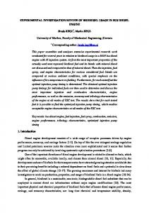
734 A2 101 100
G = 150
10–1 10–2 G = 4.5
10–3
G = 5400
ξ=0 ξ=1 ξ = 0.59
10–4 10–5 10–6 100
101
102
103 A1
Fig. 2. Amplitude dependences for dry (ξ = 0), fully (ξ = 1), and partially (ξ = 0.59) water saturated sand.
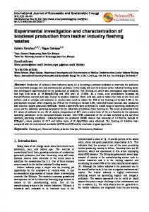
γ/β(×), 102 cm2 s 3
logG(•) 4 3
2 2 1 1
0
0.5 ξ
0 1.0
Fig. 3. Coefficient G and the ratio γ/β as functions of the relative water saturation of sand.
radiator 3 producing longitudinal waves. The radiator was fed from a power amplifier with high-frequency pulses characterized by the carrier frequency f = 100 kHz, the duration τ = 300 µs, and the repetition frequency F = 30 Hz. The acoustic pulses transmitted through the tube were received by a piezoelectric accelerometer 4 glued to the upper plug. The amplitudes A1 and A2 of the radiated and received signals were measured by a twochannel oscilloscope. In our experiments, these amplitudes were proportional to the amplitudes of the displacements U0 and U(L) in the radiated and received acoustic pulses. A preliminary checking of the radiator–receiver system showed its linearity, i.e., A2 ~ A1. In the reference experiments with a glass rod and a tube without sand, no departure from this dependence was observed. The propagation velocity of an acoustic wave in such a system, when measured by the time delay of the received signal relative to the radiated one, was
approximately 3.7 × 105 cm/s and depended only weakly on the water content in sand and on the pulse amplitude. Figure 2 shows the dependence of the amplitude A2 of the received signal on the amplitude A1 of the radiated signal for a tube filled with dry (ξ = 0) and water saturated river sand. One can see that, with an increase in the amplitude of the radiated pulse, the amplitude of the received pulse increases as follows: for small and large amplitudes, a linear dependence of A2 on A1 is observed, and for medium amplitudes, A2 grows faster than A1. In a system with dry sand, the amplitude of the received pulse increases by a factor of 1.4 × 10³ with the increase in amplitude of the radiated pulse by a factor of 3 × 10², i.e., the coefficient G characterizing the increase in the received signal relative to the radiated signal is about 4.5. This effect is called self-clarification. It results from the dissipative nonlinearity of the medium and appears in the fact that the attenuation constant of an acoustic wave decreases with an increase in its amplitude. Figure 2 also displays the experimental dependences of the amplitude A2 of the received signal on the amplitude A1 of the radiated signal for partially (ξ = 0.59) and fully (ξ = 1) water saturated sand. It is seen from this figure that, in the tube containing water saturated river sand, the self-clarification effect also exists, and the coefficient G changes (depending on the degree of water saturation of sand) in the range from 4.5 for the tube with dry sand to 7 × 10³ for the tube with partially water saturated sand (ξ = 0.49). The dependence of the coefficient G on the degree of water saturation of sand ξ is shown in Fig. 3. For the analytical description of the effect of selfclarification, we use the equation of state for a medium equivalent to the glass tube–river sand system [4, 5]: σ ( ε, ε˙ ) = σ 1 ( ε ) + σ 2 ( ε˙ ),
(1)
where σ is the longitudinal stress; σ1(ε) and σ2( ε˙ ) are the elastic and inelastic parts of the equation of state, respectively; ε = Ux is the longitudinal strain; ε˙ is the strain rate; and U is the longitudinal displacement. We neglect the elastic nonlinearity of the system and assume that σ1(ε) = Eε, where E is the elastic modulus. For describing the dissipative properties of the system, we take into account not only the usual linear viscous stress, but also the nonlinear stress. In hydrodynamics, the media exhibiting such properties are called nonNewtonian (or Bingham) ones [6, 7]. At first, we will use an exponential approximation of the nonlinear dependence σ2 = σ2( ε˙ ), which is rather general and adequately describes the initial and terminal (i.e., corresponding to low and high strain rates) parts of the self-clarification process [4, 5]: σ 2 ( ε˙ ) = ρ ( α + g ε˙ )ε˙ , m
(2)
where ρ is the density and α, g, and m are the constant coefficients determining the linear and nonlinear visACOUSTICAL PHYSICS
Vol. 47
No. 6
2001
EXPERIMENTAL INVESTIGATION OF THE SELF-ACTION OF ACOUSTIC WAVES
cous stresses in the system. Depending on the coefficient g and the exponent m, the dissipative function behaves in essentially different ways: for g > 0, the effective viscosity of the medium increases with an increase in the deformation velocity for m > 0 and decreases for m < 0; for g < 0, the effective viscosity of the medium decreases for m > 0 and grows for m < 0. Note that, for m < 0, Eq. (2) is, generally speaking, inappropriate for describing the nonlinear viscous ∞. stress near the point ε˙ ≈ 0, because σ2( ε˙ = 0) Consequently, for m < 0 and ε˙ < d [d is a certain critical strain rate, beginning from which the viscous stress can be described by Eq. (2)], the nonlinear dissipative stress should be finite. As it will be seen from the following, when m > –3, Eq. (2) can be used for any ε˙ , because no singularities occur in the final expressions. In the one-dimensional case, the equation of state (2), together with the equation of motion [11] ρU tt = σ x ( ε, ε˙ ),
(3)
and the boundary condition at the radiator U ( x = 0, t ) = U 0 sin ωt,
(4)
describes the nonlinear propagation of longitudinal acoustic waves and, in particular, the self-clarification of the medium. Substituting Eqs. (1) and (2) into Eq. (3), we obtain the nonlinear wave equation for the displacements U: U tt – C 0 U xx = αU txx + g [ U xt U xt ] x , 2
m
(5)
The solution to this equation with the boundary condition (4) has the form [12] U( x) = U 0 exp ( – δx ) { 1 + aU 0 [ 1 – exp ( – δxm ) ] } m
Φ x = 0,
gU 0 ω m
2m – 1
m+2
/C 0
Ⰶ1
(6)
should be satisfied. In this case, the solution to Eq. (5) can be found in the form of a harmonic wave at the fundamental frequency with slowly varying amplitude U(x) and phase Φ(x): U ( x, t ) = U ( x ) sin [ ωt – kx + Φ ( x ) ], ω = C 0 k.
(7)
Substituting Eq. (7) into Eq. (5), expanding the nonlinear term on the right-hand side of Eq. (5) into Fourier series, and retaining the terms corresponding to the fundamental frequency, we obtain U x cos ϑ – UΦ x sin ϑ = –δU cos ϑ – µU
m+1
cos ϑ, (8)
2(m + 1)
gΓ ( m/2 + 3/2 )ω 3 -, ϑ = where δ = αω2/2 C 0 , µ = -----------------------------------------------------1/2 m+3 π Γ ( m/2 + 2 )C 0 ωt – kx + Φ(x), and m > –3. ACOUSTICAL PHYSICS
Vol. 47
No. 6
2001
, (9)
By comparing Eq. (9) with the results of measurements (Fig. 2), it is possible, in principle, to determine the parameters of the system, namely, the coefficient g and the index m of dissipative nonlinearity. However, since the measurements were relative, it is possible to determine only the index m [4, 5]. Nevertheless, from the general form of the dependences A2 = A2(A1), it follows that, for low strain rates, we have g < 0 and m > 0, and for high strain rates, we have g > 0 and m < 0; i.e., at small wave amplitudes, the investigated system has the properties of a pseudoplastic medium, and at large amplitudes, it has the properties of a dilatant medium [6, 7]. For a small amplitude U *0 of the wave produced by radiator, when the influence of nonlinearity is negligible, Eq. (9) can be reduced to U* ( x ) = U *0 exp ( – δx ).
(10)
Dividing Eq. (9) by Eq. (10) and introducing the designations M = U(x)/U*(x), N = U0/ U *0 , and b = a U *0 m [1 – exp(–mδx)] < 0, we obtain m – 1/m
We assume that the nonlinearity of Eq. (5) is small and the equation can be solved by perturbation method. For this purpose, the condition
– 1/m
where a = µ/δ.
M/N = [ 1 + bN ]
2
where C 0 = E/ρ.
735
.
(11)
Taking the logarithm of this equation for |bNm| Ⰶ 1 two times, we derive the expression for determining the index m of dissipative nonlinearity in Eq. (2) at low strain rates: ln ( ln ( M/N ) ) = ln ( – b/m ) + m ln N.
(12)
By using the results of measurements (Fig. 2), the dependences of ln(ln(M/N)) on lnN were constructed for the system with various degrees of water saturation of sand (Fig. 4). From this figure, by the slope of the dependence of ln(ln(M/N)) on lnN, the index of dissipative nonlinearity m was determined as a function of the percentage of water in the sand ξ. The dependence of m on ξ is given in Fig. 5. From this figure, it follows that, for a tube with dry sand, m = 1, and, with the change of the water content in sand from 44 to 100% (fully water saturated sand), the index of dissipative nonlinearity changes from m = 1 to 2. At large amplitudes U *0 of the wave produced by the radiator, the influence of nonlinearity is also small, and from Eq. (9) we have U* ( x ) = U 0* exp ( – δx ).
(13)
NAZAROV et al.
736
As before, we divide Eq. (13) by Eq. (9), introduce the designations P = U*(x)/U(x), R = U 0* /U0, and b = a U 0* [1 – exp(–mδx)] < 0, and derive (for |bR–m| Ⰶ 1)
ln(ln(M/N)) 3 m = 1.22
2
ln ( ln ( P/R ) ) = ln ( b/m ) – m ln R. 1
m=1
0
ξ=0 ξ=1 ξ = 0.59
–1 –2 –3
m=2
0
1
2
3
4
5
6 ln(N)
Fig. 4. Amplitude dependences for dry, partially, and fully water saturated sand for small amplitudes.
m 2.0 1.5 1.0 0.5
0.5
0
1.0 ξ
Fig. 5. Index of dissipative nonlinearity m as a function of the relative water saturation of sand.
ln(ln(P/R)) 3
For this case, using the results of measurements (Fig. 2), we also constructed the dependences of ln(ln(P/R)) on lnR for a tube with sand with various degrees of water saturation (Fig. 6). From this figure, it follows that, for high strain rates, m ≅ –2 and does not depend on the water content in sand. Thus, in choosing the dissipative component in the equation of the state of a system with dry and water saturated sand to describe the process of self-clarification in the whole range of amplitudes of acoustic waves, it is necessary to take into consideration the following requirements: (i) at low and high strain rates, the system is linear and characterized by two different attenuation constants, the ratio of which determines the coefficient G of relative growth of amplitudes at the output and input of the system; (ii) at low strain rates, the parameter of dissipative nonlinearity is g < 0 and the index m changes (depending on the water content) from m = 1 to m = 2; and (iii) at high strain rates, the parameter of dissipative nonlinearity is g > 0 and the index m is m = –2 (regardless of the water content). We now consider the equations of state describing the system under study. The most simple expression for the dissipative component complying with the aforementioned requirements corresponds to the system with fully water saturated sand. It can be written as γ ε˙ σ 2 ( ε˙ ) = αρε˙ – --------------------2 ρε˙ , 1 + β ε˙ 2
(15)
where β and γ are positive coefficients. Substituting Eq. (15) into Eq. (3), we obtain, similarly to Eq. (8), the following equation for the wave amplitude U(x):
m = –2
2
(14)
αω dU = – ---------3- U dx 2C 0 2
1 ξ=0 ξ=1 ξ = 0.59
0 –1 –2 –3
0
1
2
3
4
5
6 ln(R)
γ 2 1 × 1 – ------- 1 – ----------------------2 1 – ------------------------------------ . 2 αβ β ( ωkU ) 1 + β ( ωkU )
(16)
Due to the complex nonlinearity of this equation, it is impossible to obtain its analytical solution. Therefore, we will consider the limiting cases of small and large amplitudes. For small amplitudes (βω2k2U2 Ⰶ 1), from Eq. (16) we derive the equation αω dU 2 = – ---------3- U [ 1 – a 1 ( kU ) ], dx 2C 0 2
Fig. 6. Amplitude dependences for dry, partially, and fully water saturated sand for large amplitudes.
ACOUSTICAL PHYSICS
Vol. 47
No. 6
2001
EXPERIMENTAL INVESTIGATION OF THE SELF-ACTION OF ACOUSTIC WAVES
which has the solution
For the system with dry and partially water saturated sand, the dissipative component of the equation of state has a more complex form, as compared to Eq. (15). It can be represented by the expression
αω 2 U ( 1 – a1 k U 0 ) -x ------------------------------------= exp – --------2 2 2 2 U 0 ( 1 – a1 k U ) C0 2
2
737
2
γ ε˙ σ 2(ε˙ ) = αρε˙ – --------------------m- ρε˙ { H(ε˙ + ε˙ th) – H(ε˙ – ε˙ th) } 1 + β ε˙ (20) 2 ε˙ th γ – --- 1 – ----------------------------- ρε˙ {1 – H(ε˙ + ε˙ th) + H(ε˙ + ε˙ th)}, 2 m β ε˙ (1 + βε˙ th) m
or αω 2 U ( x ) = U 0 exp – ---------3- x 2C 0 αω 2 2 2 - x × 1 – a 1 k U 0 1 – exp – --------3 C 0
(17)
– 1/2
,
where a1 = 3γω2/4α. It is readily seen that, for a = –a1 and m = 2, Eqs. (9) and (17) coincide. For large amplitudes (βω2k2U2 Ⰷ 1), from Eq. (17) we obtain αω k γ 2γ dU - 1 – ------- + --------------------------2 , = – -----------3 αβ dx 2C 0 α ( βωkU ) 2
and this equation has the solution 2 ναω 2 U + γ /ν -------------------x = exp – ------------3 2 U 0 + γ /ν C0
or ναω 2 x U ( x ) = U 0 exp – ------------3 2C 0
(18)
a2 ναω 2 -2 1 – exp ------------x , × 1 – ------3 νε 0 C 0
where a2 = 2γ/αβ2ω2 and ν = 1 – γ/αβ. From the comparison of Eqs. (9) and (18), it follows that, when δ = 3 ναω2/2 C 0 , a = a2/ν, and m = –2, they coincide and, consequently, the equation of state (15) satisfies the above requirements and can be used for describing the process of self-clarification in a tube with fully water saturated sand. Now it is possible to determine the coefficient G equal to the ratio U2/U1, where U2 and U1 are the amplitudes of the displacements at the receiver, which are chosen on the linear portions of the curves given by Eqs. (18) and (17), respectively, for the same value of the amplitude U0 at the radiator: γ ω2 G = exp -------------3 L . 2βC 0
(19)
From Eq. (19), it follows that the coefficient G is determined by the ratio of the parameters γ and β. ACOUSTICAL PHYSICS
Vol. 47
No. 6
2001
where H( ε˙ ) is the Heaviside function, ε˙ th is a certain threshold value of ε˙ at which a continuous transition from one nonlinearity [the second term in Eq. (20)] to the other (the third term) occurs. It can be easily shown that, for low and high strain rates, Eqs. (2) and (20) coincide qualitatively. Consequently, the solution to the equation of motion with this kind of nonlinearity in the limiting cases of small and large amplitudes will coincide with solution (9). In this case, in Eq. (9) it is necessary to assume that, at low m γ ω Γ ( m/2 + 3/2 ) - --------------------------------- , and at high strain strain rates, a = -----------1/2 απ Γ ( m/2 + 2 ) 2 2 ε˙ th 3γ ω α – --γ- --------. rates, a = – --------- ----------------------, where δ = 4βδ ( 1 + βε˙ mth ) β 2C 30 Then, the coefficient G will be determined by Eq. (19) from which it is possible to extract the ratio of the parameters γ and β. Figure 3 shows the ratio γ/β as a function of water saturation of sand ξ. From this figure, it follows that the ratio γ/β varies most rapidly in the range 0 ≤ ξ ≤ 0.44, and in the range 0.44 ≤ ξ ≤ 1, the ratio γ/β ≈ const and the index m grows steadily from m = 1 to 2. Thus, in this paper, we presented the results of the experimental study of the self-action of acoustic waves in a glass tube filled with dry and water saturated river sand: with increasing wave amplitude, the effect of selfclarification was observed in this system. On the basis of the amplitude relations obtained in the experiment, the phenomenological equations of state were proposed for these systems and the values of their parameters were determined. It was found that the parameters of dissipative nonlinearity of the system depend on the degree of water saturation of sand. This suggests that the effect of self-clarification can be used for the diagnostics of the state of porous gas and water saturated media. In conclusion, we note that the choice of the dissipative nonlinearity in equations of state (2), (15), and (20) is not unambiguous in the sense that the coefficient determining the nonlinear viscosity of the system may depend not only on the strain rate but also on the strain. However, this will not affect the results of the analytical calculations of the index m of dissipative nonlinearity (because the amplitude dependences do not change in
NAZAROV et al.
738
this case) and will only lead to a renormalization of the constant coefficients g, γ, and β. To determine on which parameters (ε or ε˙ ) the nonlinear viscosity of the system depends, it is necessary to carry out an experiment that will reveal the frequency dependence of the dissipative nonlinearity [3]. The results of this experiment will be presented in the following paper. ACKNOWLEDGMENTS This work was supported by the Russian Foundation for Basic Research (project nos. 01-05-64417 and 00-05-64252) and by the Interdepartmental ScientificEngineering Center (project no. 1369). REFERENCES 1. S. V. Zimenkov and V. E. Nazarov, Fiz. Zemli, No. 1, 13 (1991). 2. R. A. Guyer and P. A. Johnson, Phys. Today 52 (4), 30 (1999). 3. V. E. Nazarov, Fiz. Met. Metalloved. 88 (4), 82 (1999).
4. V. E. Nazarov and S. V. Zimenkov, Acoust. Lett. 16 (10), 218 (1993). 5. V. E. Nazarov, Akust. Zh. 41, 349 (1995) [Acoust. Phys. 41, 305 (1995)]. 6. W. Wilkinson, Non-Newtonian Fluids; Fluids Mechanics; Mixing and Heat Transfer (Pergamon, New York, 1960; Mir, Moscow, 1964). 7. Z. P. Shul’man, Lectures on Reophysics (Nauka i Tekhnika, Minsk, 1976). 8. V. A. Pal’mov, Prikl. Mat. Mekh. 31 (4), 749 (1967). 9. V. N. Nikolaevskiœ, Izv. Akad. Nauk SSSR, Mekh. Tverd. Tela, No. 4, 85 (1968). 10. V. A. Pal’mov, Vibrations of Elastically-Plastic Bodies (Nauka, Moscow, 1968). 11. L. D. Landau and E. M. Lifshits, Course of Theoretical Physics, Vol. 7: Theory of Elasticity (Nauka, Moscow, 1987; Pergamon, New York, 1986). 12. E. Kamke, Gewöhnliche Differentialgleichungen (Academie, Leipzig, 1959; Nauka, Moscow, 1976).
Translated by A. Svechnikov
ACOUSTICAL PHYSICS
Vol. 47
No. 6
2001