Microscopy Microanalysis
Microsc. Microanal. 14, 306–314, 2008 doi:10.1017/S1431927608080379
AND
© MICROSCOPY SOCIETY OF AMERICA 2008
Experimental Method to Determine the Absolute Efficiency Curve of a Wavelength Dispersive Spectrometer Jorge Trincavelli,1,2, * Silvina Limandri,1,2 Alejo Carreras,2,3 and Rita Bonetto 2,4 1
Facultad de Matemática, Astronomía y Física, Universidad Nacional de Córdoba, Ciudad Universitaria, 5000, Córdoba, Argentina 2 Consejo Nacional de Investigaciones Científicas y Técnicas de la República Argentina, Ciudad Universitaria, 5000, Córdoba, Argentina 3 Instituto de Investigaciones en Tecnología Química, Universidad Nacional de San Luis, CC 290, 5700, San Luis, Argentina 4 Centro de Investigación y Desarrollo en Ciencias Aplicadas Dr. Jorge Ronco, Calle 47 N o 257; Facultad de Ciencias Exactas y Facultad de Ingeniería de la UNLP, 1900 La Plata, Argentina
Abstract: A method for the experimental determination of the absolute efficiency of wavelength dispersive spectrometers was developed, based on the comparison of spectra measured with a wavelength dispersive system and with an energy dispersive spectrometer. The aim of studying this parameter arises because its knowledge is necessary to perform standardless analysis. A simple analytical expression was obtained for the efficiency curve for three crystals ~TAP, PET, and LiF! of the spectrometer used, within an energy range from 0.77 to 10.83 keV. Although this expression is particular for the system used in this work, the method may be extended to other spectrometers and crystals for electron probe microanalysis and X-ray fluorescence. Key words: detection efficiency, wavelength dispersive X-ray spectrometer, electron probe microanalysis, standardless microanalysis
I NTR ODUCTION The detection efficiency « of an X-ray spectrometer is a measurement of the probability of detecting an emitted photon; it depends on the photon energy and on certain characteristics of the spectrometer. A detailed knowledge of this dependence may not be necessary for some analytical routine applications involving standards, since the efficiency is the same for sample and standard, and they cancel out. Nevertheless, a full description of the efficiency is crucial for quantitative standardless analysis as stated by Fournier et al. ~1999! and Goldstein et al. ~1994! and for the determination of atomic parameters; see, for example, Merlet et al. ~2006!, Merlet and Llovet ~2006!, Bonetto et al. ~2004!, and Trincavelli et al. ~2002!. In the particular case of a wavelength dispersive spectrometer ~WDS!, to have reliable information of the efficiency becomes a must, due to the great variations of this parameter with photon energy, which could produce large errors. In wavelength dispersive systems, the spectrum is acquired by varying the position of an analyzing crystal, which diffracts the X-rays coming from the sample accordReceived February 22, 2008; accepted March 25, 2008 *Corresponding author. E-mail:
[email protected]
ing to Bragg’s law. The geometrical arrangement contains the X-ray source ~that is to say, the sample!, the crystal, and the detector on the perimeter of a circle of radius r, known as the Rowland circle. The crystal planes are bent to radius 2r and the crystal surfaces can be ground to radius r ~Johansson geometry! or not ~Johann geometry!. The X-rays diffracted by the crystal are usually collected by gas-filled proportional counters. For these kind of spectrometers, the efficiency «WDS is difficult to predict and depends on the quantum efficiency of the proportional counter, on geometrical factors, and on the reflectivity of the analyzing crystal. Three semiempirical methods to determine «WDS were reported. One of them involves the measurement of characteristic line intensities for different pure elements: the ratio between measured intensities and the ones predicted by an analytical model serves as estimation for «WDS ~Wernisch, 1985!. In the second one, a spectrum is measured for a single-element sample without characteristic lines in the region of interest and compared with an analytical prediction for bremsstrahlung ~Smith & Reed, 1981!. The third method, explained by Merlet et al. ~2006! and Merlet and Llovet ~2006!, is similar to the previous one, but the bremsstrahlung emission was obtained by Monte Carlo simulation. The disadvantage of these methods is that they need a good description of the spectrum, which cannot be given
Method to Determine the Efficiency of a WDS
Table 1.
Main Characteristics of the Crystals Used in This Work
Name Thallium acid phthalate ~TAP! Pentaerythritol ~PET! Lithium fluoride ~LiF!
Formula
Plane
2d ~nm!
Range ~keV!
C8H5O4Tl
101
2.59
0.521–1.675
C5H12O4
002
0.874
1.675–4.993
LiF
200
0.403
4.993–10.839
with the required degree of accuracy; in addition, they are restricted to electron excitation beams. The third method involves the prediction of bremsstrahlung from thin targets instead of thick targets; thus, it is more precise than the other two, although the uncertainties obtained can reach 10% for energies around 1 keV. A different strategy was developed in this work, based on the comparison of two experimental spectra: one of them measured with an energy dispersive spectrometer ~EDS! and the other with the wavelength dispersive spectrometer whose efficiency is to be determined.
E XPERIMENTAL Measurements were performed with a scanning electron microscope LEO 1450VP at the Laboratorio de Microscopía Electrónica y Microanálisis ~LABMEM! of the Universidad Nacional de San Luis, operated in the high vacuum mode, i.e., with a chamber pressure of 0.5 Pa. This equipment is furnished with an energy dispersive spectrometer EDAX Genesis 2000 with a resolution of 129 eV for the Mn-Ka line ~5.893 keV! and with a wavelength dispersive spectrometer INCAWAVE 700. The energy dispersive detector is a Si~Li! SUTW Sapphire with ultrathin polymer window and aluminum ohmic contact. The crystal front area is 10 mm 2, with a circular collimator with an aperture of ~7.7 6 0.2! mm 2. The distance of this collimator from the source is 6.9 cm. The ultrathin window is a Moxtek AP3.3 containing a 380 mm thick silicon support structure with 77% open area. The window itself is composed of: polymer—300 nm thick, density 1.4 g/cm 3 ~69% C, 3% H, 21% O, and 7% N mass concentrations!; aluminum—30 nm thick, density 2.7 g/cm 3 ; and boron hydride—20 nm thick, density 2.0 g/cm 3 ~92% B and 8% H mass concentrations!. The dead layer thickness was estimated to be about ~72 6 17! nm by means of the method suggested previously by Bonetto et al. ~2001!. The arrangement of the WDS system is Johansson type for the crystals used in this work: TAP, PET, and LiF. Some of their characteristics are specified in Table 1. The photons diffracted by the analyzing crystal are collected by two
307
Table 2. Experimental Conditions for the Measurement of Carbon Spectra Spectrometer ~and crystal!
Potential ~kV!
Take-off angle
Average beam current ~nA!
Acquisition live time
WDS ~TAP! WDS ~PET! WDS ~LiF! EDS
15 15 15 15
298 298 298 298
114 162 117 0.516
3 h, 34 min 6 h, 18 min 3 h, 14 min 2 h, 50 min
proportional counters operated in tandem: the first of them is a P10 ~90%Ar-10%CH4 ! flow counter at a pressure of 1 atm and the second is a sealed Xe counter. To determine the WDS efficiency, spectra were collected from a carbon standard: three with the WDS system ~one for each of the crystals indicated in Table 1! and another with the EDS, all in the area scan mode, under the experimental conditions shown in Table 2. To perform the determination of «WDS , the beam current must be known for each wavelength of the WDS spectra. The equipment does not allow a direct measurement of this current while the spectrum is being acquired, but instead gives information about the current flowing from the sample to earth ~known as specimen current!. Fluctuations in the beam current were monitored from the variations registered for the specimen current, on the basis of the constant relationship between these two currents for a given sample and incidence energy.
D EVELOPMENT
OF THE
M ETHOD
The absolute efficiency « of a spectrometer is defined as the ratio between the X-ray intensity registered by the detector and the X-ray intensity emitted by the source. It can be divided in two factors: the intrinsic efficiency « ' and the geometric efficiency. The geometric factor is given by the fraction of radiation arriving to the detector, while the intrinsic efficiency is the fraction of the X-rays arriving to the detector that are actually registered. In the case of a WDS, the efficiency «WDS depends on two factors: the solid angle DV subtended from the source to the crystal region capable of diffraction and the intrinsic efficiency of the proportional counter ~Reed, 2002!. The efficiency «WDS could be predicted theoretically by considering the mentioned factors, but its calculation would be affected by rough approximations and large uncertainties. Assuming that all the diffracted X-rays reach the proportional counter system, which is reasonable due to the large area of its window, the absolute efficiency could be expressed as
308
Jorge Trincavelli et al.
and NWDS ~l! ⫽ ~iDt !WDS f ~Z, Eo , l!
DEWDS Dl
' ~l! Dl AR«WDS
DV 4p
,
~4!
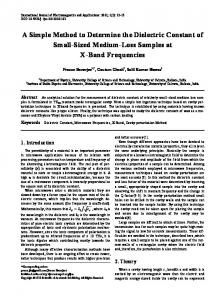
Figure 1. Incidence out of the Rowland plane in Johansson geometry. The Bragg angle for ray 2 is slightly smaller than the angle u corresponding to ray 1. The grey band lying along the center of the crystal indicates the area from which total reflection occurs.
pred
«WDS ~E ! ⫽
DV~E! 4p
' ~E !, «WDS
~1!
' where «WDS denotes the intrinsic efficiency of the counters and is also the intrinsic efficiency of the entire system. The factor DV can be estimated considering that the rays incident on the crystal out of the plane of the Rowland circle form a lower angle u than those lying in this plane. Due to the small value of the integrated reflectivity R i , reflection occurs only in a narrow band along the center of the crystal ~see Fig. 1!. According to Reed ~1993!, for Johansson geometry,
DV ⫽
l
M 2R i cot u, r
~2!
where l is the length of the illuminated region of the crystal along its bent dimension. ' Regarding the efficiency «WDS , all the specifications necessary for its determination ~counter dimensions, window thicknesses, aluminum coating thickness, gas pressures, etc.! are usually not available for the analyst. On the other hand, there is no general information available on the integrated reflectivity of nonperfect crystals. Due to these difficulties, the absolute efficiency «WDS was directly measured. For this purpose, two spectra for a single-element sample were measured: one of them with a WDS and the other one with an EDS, at the same incidence energy and take-off angle. The number of counts N recorded for each spectrum in the region free of peaks during the interval Dt can be written as
' ~E ! NEDS ~E ! ⫽ ~iDt !EDS f ~Z, Eo , E !DEEDS AR«EDS
DVEDS 4p ~3!
where i is the beam current, Dt characterizes the measurement time, f is a function to predict the bremsstrahlung generation per incident electron and energy interval as a function of the sample atomic number Z, the beam energy Eo and the photon energy E ~or its wavelength l!, DEEDS is the channel width of the EDS, A is the absorption correction, R takes into account the intensity losses due to backscattered electrons, « ' ~E ! is the intrinsic efficiency of the detection system, DVEDS is the solid angle subtended by the Si~Li! detector, DV is the solid angle subtended from the source to the crystal reflecting area, as defined above, DEWDS ⫽ E~l! ⫺ E~l ⫹ Dl! is the energy interval corresponding to the channel width Dl of the WDS. The parameter Dt indicates the acquisition live time in the case of EDS and the acquisition time for each channel for the WDS. To perform a comparison between both spectra, the WDS spectra were processed transforming their channels from wavelength to energy, and then counts were grouped so that each new channel represents an interval of 10 eV, equal to the channel width DEEDS of the energy dispersive system. The expression for the number of counts obtained with WDS may be written from equation ~4! as follows: grouped
NWDS
~E ! ⫽ ngrouped ~E !~iDt !WDS f ~Z, Eo , E ! ⫻
E2 hc
' ~E ! Dl AR«WDS
DV 4p
,
~5!
where ngrouped ~E ! is the number of channels grouped around the energy E. The relationship between wavelength and energy ~E ⫽ hc/l! was used to calculate DEWDS /Dl, where h is Planck’s constant and c is the velocity of light in vacuum. The number of grouped channels depends on the energy in the following way: ngrouped ~E ! ⫽ hc
DEEDS 1 Dl
E2
.
~6!
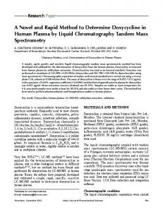
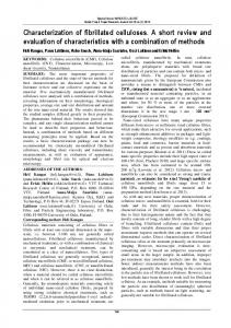
In Figure 2, spectra of a carbon sample measured with the three crystals are shown, as well as the corresponding spectra obtained by the channel processing aforementioned. Figure 3 shows an EDS spectrum of the same sample. The product f{A{R, which would require a theoretical expression, does not depend on the spectrometer because the take-off angle involved is the same for both detection systems ~see Table 2!; thus, it is cancelled out when performing the ratio between the processed WDS spectrum and the EDS spectrum. Then, from equations ~3!, ~5!, and ~6!, a
Method to Determine the Efficiency of a WDS
309
Figure 3. EDS spectrum normalized by the beam current and the acquisition time from a carbon sample. The grey bars indicate peak regions, which were subtracted from the spectrum, corresponding to C-K and O-K, Si-K, S-K, Cl-K, K-K, Cr-Ka, Fe-Ka, Fe-Kb, and Ni-Ka in order of increasing energy.
inherent to peak deconvolution, or to work with several spectra. On the other hand, a detailed description of the peak shape produced by both spectrometers would be required, which complicates the method introducing more uncertainties.
R ESULTS Figure 2. WDS spectra normalized by the beam current and the acquisition time from a carbon sample measured with three different crystals: TAP, PET, and LiF. ~a! Raw spectra and ~b! number of counts grouped according to the EDS channel width—see equations ~5! and ~6!. The grey bars indicate the peak regions that were subtracted from spectra, corresponding to C-K and O-K, Si-K, S-K, Cl-K, K-K, Cr-Ka, Fe-Ka, Fe-Kb, and Ni-Ka in order of increasing energy.
good estimation for the absolute efficiency of the wavelength dispersive system can be obtained: grouped
«WDS ~E ! ⫽
NWDS
~E !~iDt !EDS DVEDS
NEDS ~E !~iDt !WDS
4p
' ~E !. «EDS
~7!
It is interesting to note that the number of counts involved in equation ~7! correspond to bremsstrahlung; an alternative possibility would have been to compare peak counts obtained with both spectrometers. This strategy is less convenient because it would be necessary either to process spectra with a great number of peaks, with the problems
As mentioned in the previous section, the method to determine the WDS efficiency was applied using a carbon sample because it does not present characteristic peaks above 0.3 keV. Nevertheless, small amounts of impurities and spurious radiation produced some additional peaks, which were subtracted. The intervals where these peaks are appreciable are shown with grey bars in Figures 2b and 3. As can be seen, some of the peaks present in WDS spectra, even after channel grouping, are not appreciable in the EDS spectrum. Low statistics of original WDS spectra, in spite of measuring during several hours ~see Table 2!, is due to the poor emission of carbon. This problem is solved when channels are grouped simulating the EDS spectrum. As can be inferred from equation ~7!, to determine the efficiency of the wave dispersive system by means of the present method, it is necessary to know the EDS efficiency. ' , it must be borne in mind that to To determine «EDS actually count a photon, it must arrive to the detector active region passing through several layers: the window ~which keeps the system at vacuum!, the metallic ohmic contact, and the so-called dead layer ~DL!, where detection is not possible. Taking into account the different layers of the ' of the detector open detector, the intrinsic efficiency «O.A.
310
Jorge Trincavelli et al.
area, i.e., the detector region not hidden behind the silicon supporting grid is given by ' «O.A. ⫽ e ⫺~ mrx!win e ⫺~ mrx!Al e ⫺~ mrx!DL ~1 ⫺ e ⫺~ mrx!det !,
~8!
where ~ mrx!i is the product of the mass absorption coefficient, the density, and the thickness of the ith detector layer. The first factor in the right-hand member of equation ~8! is related to the attenuation of the incident photons in the polymer window, the second one accounts for the photon losses in the aluminum ohmic contact, the third one takes into account the absorption in the dead layer, and the last one is the probability that a photon be absorbed in the detector active region. Considering also the silicon grid that acts as a supporting structure of the detector window ~see the Experimental section!, the following expression is obtained for the intrinsic EDS efficiency: ' ' ' ⫽ 0.77«O.A. ⫹ 0.23«O.A. e ⫺m Si rSi x Grid, «EDS
~9!
where x Grid is the supporting grid thickness, and mSi and rSi are the mass absorption coefficient and density of the grid material ~silicon in this case!, respectively. The first term of equation ~9! takes into account the arrival of photons to the detector open area, which represents 77% of the total detector area, whereas the second one accounts for the fraction that previously passed through the grid. Mass absorption coefficients used for the determina' were calculated by means of the program tion of «EDS FFAST performed by Chantler et al. ~2005!. In the energy range studied, the EDS intrinsic efficiency varies between 0.56 ~for 0.77 keV! and 0.79 ~for 10.83 keV!. Figure 4 shows this efficiency for the Si~Li! detector used, calculated according to equation ~9! ~solid line!. It is important to take properly into account the effect produced on the efficiency curve by the silicon support structure. As can be seen from Figure 4, this effect is particularly noticeable at high energies. For low energy photons the efficiency can be well approximated by the dotted line, which represents the efficiency that is obtained by excluding the area of the supporting grid, i.e., for a hypothetical detector with an effective area of 77% of the total area. For higher energy photons, the curve tends to the one obtained when considering all the detector area as effective for detection, i.e., ignoring the supporting structure. This trend is expected because these photons have a higher probability of traversing the grid and, thus, of arriving to the active region. The inset in Figure 4 shows the energy range of interest for the present work along with the influence of the uncertainties of mass absorption coefficients and characteristic detector thicknesses. To this end, error propagation was performed on equations ~8! and ~9! assuming errors of 20 and 25% in the mass absorption coefficients
Figure 4. Intrinsic efficiency of the energy dispersive system ~solid line! along with the approximate trends for low energies ~i.e., excluding the area of the silicon supporting grid ~dotted line!! and for high energies ~i.e., ignoring the effect of the silicon structure ~dashed line!!. Inset: the influence of the uncertainties in mass absorption coefficients and characteristic detector thicknesses are displayed with thin solid lines.
Figure 5. Absolute WDS efficiency for the three crystals studied— TAP, PET, and LiF—obtained from equation ~7!.
and in the characteristic thicknesses, respectively. The largest relative errors occur in a very restricted range at low energies: 7.9% at 0.77 keV, whereas they reach its minimum value of 0.06% around 7 keV. Finally, from equation ~7! and using the expression ' according to equations ~8! and ~9!, values derived for «EDS for the efficiency «WDS were obtained as a function of photon energy. The corresponding results can be seen in Figure 5. The error bars ~not visible for TAP! were calculated by neglecting the uncertainties in the EDS efficiency, i.e., just propagating the errors of the registered counts NEDS grouped and NWDS .
Method to Determine the Efficiency of a WDS
Table 3.
Fitting Constants for the Absolute WDS Efficiency
Crystal
a0 ~⫻10⫺4 !
a1 ~⫻10⫺4 !
a2 ~⫻10⫺4 !
TAP PET LiF
⫺28 6 2 1.4 6 0.7 363
59 6 3 ⫺1.8 6 0.4 ⫺2.1 6 0.8
⫺14 6 1 1.74 6 0.06 0.77 6 0.05
Discontinuities can be observed at the energies corresponding to the range limits of each crystal. These efficiency gaps are due to two reasons: on the one hand, to the change of reflectivity for different crystals and, on the other hand, to the variation of the diffraction angle u, because for a given energy E, a change of crystal implies a variation of the interplanar distance d, and hence of the Bragg angle. Performing the ratio of the experimental grouped counts obtained with two crystals i and j at the transition energy, from equation ~5!, and assuming that the estimation given by equation ~2! is adequate, the relative integrated reflectivity can be obtained: Ni Nj
⫽
DVi DVj
⫽
i i
i
j i
cot uj
M R cot u
MR
⫽
冉 冊冉 R ii j
Ri
0.5
4di2 E 2 ⫺ 12.398 2 4dj2 E 2 ⫺ 12.398 2
冊
0.25
from where the values of relative reflectivity can be derived: R iTAP R iPET
⫽ 17.5
and
R iPET R iLiF
⫽ 3.5.
The information available for integrated reflectivity of nonperfect crystals is very scarce; then it is very important to rely on experimental values, even of relative reflectivity. As can be seen in Figure 5, the values obtained for «WDS present a smooth trend for each crystal. For this reason, second-order polynomials were fitted to obtain simple analytical expressions to describe the WDS efficiency: «WDS ⫽ a 0 ⫹ a 1 E ⫹ a 2 E 2.
~10!
If the photon energy is expressed in kiloelectron-volts, the constants take the values shown in Table 3. The large dispersion of data for crystal LiF is due to the low emission of carbon combined with the small number of grouped channels ngrouped , which decrease as E 2 ~see equation ~6!!. This dispersion produces important uncertainties in the fitting coefficients.
D ISCUSSION The method developed in this work involves two sources of error: uncertainties in the measured spectra ~also present in
311
any of the methods mentioned in the Introduction! as well as in the determination of the EDS efficiency. For the first source, errors can be estimated from counting statistics, while in the second one, the main difficulty is to know all the characteristic detector thicknesses and the corresponding mass absorption coefficients with accuracy. The influence of these parameters was investigated as shown in Figure 4 and explained in the previous section. The overall uncertainty may be inferred from the errors in the fitting parameters given in Table 3. Figure 6 shows the fitting of the efficiency curves for the three crystals studied, along with the error bands obtained by propagating the uncertainty of the corresponding coefficients. The values obtained by using the method proposed by Smith and Reed ~1981! are also shown in Figure 6 for comparison. According to this model, ratios between measured and calculated number of counts are used to estimate the absolute efficiency except for a scale factor. Bremsstrahlung generation was predicted by means of the model given by Smith and Gold ~1979!; that is to say, the one suggested in the original paper by Smith and Reed ~1981!, whereas the absorption correction was performed by using the model based on the ionization depth distribution function given by Packwood and Brown ~1981! with coefficients modified by Riveros et al. ~1992!. Although the energy dependence of the bremsstrahlung cross section is different from that corresponding to ionization, the differences are partially masked because of electron straggling in the target. Therefore, it is a reasonable assumption to consider the depth distribution of continuum X-ray production to be similar to that of characteristic radiation. The same effect of straggling blurs the bremsstrahlung emission anisotropy. The backscattering correction was performed according to Statham ~1979!. The main disadvantage of calculating efficiency with this model is that an accurate expression for bremsstrahlung emission is required, which is a problem due to the important discrepancies reported among the different models proposed and experimental values. These discrepancies are more severe in the low energy region, where the continuous spectrum presents a maximum. Moreover, the absorption correction is very important in this region ~becoming a factor 0.26 at the lowest energy E ⫽ 0.77 keV!, and any uncertainty in the model used or in mass absorption coefficients strongly influences the predicted efficiency. The discrepancies between experimental data and bremsstrahlung predictions can exceed 25% for the most successful models as was observed by Castellano et al. ~2004!. The comparisons shown in Figure 6 were performed by multiplying the curves obtained by means of the prediction given by Smith and Reed ~1981! by scale factors, so that they coincide with the experimental data at the middle of the energy range of each crystal. It can be seen that the resulting function approximates the experimental values quite adequately for PET and LiF crystals, while for TAP crystal, the discrepancies may be larger than 20%.
312
Jorge Trincavelli et al.
Figure 7. Hematite spectrum measured with the TAP crystal. Experimental values ~grey solid line!, values obtained with the efficiency model developed in this work ~black solid line!, and results obtained by using the model of efficiency given by Smith and Reed ~1981! ~dashed line!. The peaks that appear in the spectrum correspond to Fe-Lb3,4 , Al-Ka, and Al-Kb, in order of increasing energy. The aluminum peaks are due to an impurity.
x2 ⫽
Figure 6. Fitting of the absolute efficiency curves for ~a! TAP, ~b! PET, and ~c! LiF crystals. Values obtained in this work ~dots!, polynomial fit ~thick solid line!, fitting error band ~dotted lines!, and results obtained by using the model given by Smith and Reed ~1981! ~thin solid line!.
In order to evidence these discrepancies, a hematite spectrum measured with the TAP crystal is shown in Figure 7. The parameter x 2 was introduced as a measure of the goodness of fit:
1 N⫺P
(i
~ ID i ⫺ Ii ! 2 Ii
,
where N is the number of channels in the spectrum, P is the number of parameters fitted ~in this case three parameters were fitted, one corresponding to the bremsstrahlung scale factor and the other two being LI and K peak scale factors, necessary to describe the iron Lb3,4 and aluminum K lines, the last one caused by an impurity!, and ID i and Ii are the predicted and experimental X-ray intensities, respectively, for the energy Ei of the channel i. The expression for bremsstrahlung given by Castellano et al. ~2004!, the model for backscattering correction proposed by Statham ~1979!, and the expressions for peak generation and absorption developed by Riveros et al. ~1992! were used to predict the spectrum. The generation of the whole spectrum was achieved by means of the optimization method implemented in the program POEMA ~Bonetto et al., 2001!, which involves all the mentioned expressions along with the required instrumental and atomic parameters. The values obtained for x 2 were 1.17 and 1.27 with the model for the efficiency given by equation ~10! and that obtained with the method given by Smith and Reed ~1981!, respectively. The greater value of x 2 obtained with the latter is caused by the fitting overestimation at high energies and an underestimation occurring at low energies. The comparison was performed only with Smith and Reed’s model, since the other methods published involve the prediction of characteristic peaks, which introduce greater uncertainties,
Method to Determine the Efficiency of a WDS
or the use of a Monte Carlo simulation code, not always available. It must be emphasized that the good performance shown by the method proposed for the determination of the WDS efficiency may be used to elaborate a strategy of standardless analysis. For instance, the method of parameter optimization implemented in the POEMA routine ~Bonetto et al., 2001! could be furnished with the WDS efficiency data provided by the present work with the aim to perform standardless quantification. That method consists of minimizing the differences between an experimental X-ray spectrum and a function proposed to account for the bremsstrahlung and characteristic peaks from the corresponding sample, as well as for detection artifacts. This complicated function involves several parameters related to different sources ~X-ray production, X-ray attenuation, sample composition, X-ray detection, etc.!. Initial values must be supplied for them, and after a numerical iterative procedure is performed, improved values are achieved. Depending on the particular situation, certain parameters may be known a priori, so that they can be fixed, allowing the others to vary. When the parameters to optimize are the mass concentrations, the routine becomes a standardless quantification tool, provided that the detector efficiency and certain atomic parameters are well known. On the other hand, this routine also allows the determination of instrumental characteristics ~Visñovezky et al., 2007! and relative transition probabilities ~Castellano et al., 2002; Trincavelli et al., 2002; Carreras et al., 2005!. The knowledge of wavelength dispersive efficiency will enable to improve some of the previous results and to obtain other ones such as natural linewidths and relative transition probabilities of overlapped spectral lines due to the better resolution of WDSs.
C ONCLUSIONS A method for the experimental determination of the absolute detection efficiency of a wavelength dispersive system was developed. This parameter is necessary to carry out standardless quantification routines, as well as for the determination of atomic parameters from spectral analysis. The present method is based on performing the ratio of spectra measured with the WDS studied and with an EDS, corrected by an estimation of the absolute efficiency of the latter. The uncertainties introduced by this estimation are small compared to those involved in any model used to describe characteristic and continuous emission. Therefore, the present method leads to more precise results than the previous proposed ones, which require spectral descriptions. Simple analytical functions were obtained for the efficiency curves for energies between 0.77 and 10.83 keV for the three crystals used: TAP, PET, and LiF. Even when these expressions correspond to the spectrometer used in this particular case, the method is of general applicability and
313
could be extended to other spectrometers, either for electron probe microanalysis or X-ray fluorescence, provided that both EDS and WDS are available. Results obtained with the present strategy were compared to the method developed by Smith and Reed ~1981!. It could be observed that the latter works properly for intermediate and high energies. Nevertheless, it presents great discrepancies with the values obtained with the experimental method proposed here, in the TAP energy region. These differences are mainly due to the great uncertainties in the prediction of bremsstrahlung emission at low energies, which are avoided in the present method.
A CKNOWLEDGMENTS This work was partially supported by the Consejo Nacional de Investigaciones Científicas y Técnicas de la República Argentina and the Secretaría de Ciencia y Técnica de la Universidad Nacional de Córdoba, Argentina.
R EFER ENCES Bonetto, R., Carreras, A., Trincavelli, J. & Castellano, G. ~2004!. L-shell radiative transition rates by selective synchrotron ionization. J Phys B: At Mol Opt Phys 37, 1477–1488. Bonetto, R., Castellano, G. & Trincavelli, J. ~2001!. Optimization of parameters in electron probe microanalysis. X-Ray Spectrom 30, 313–319. Carreras, A., Trincavelli, J., Bonetto, R. & Castellano, G. ~2005!. Determination of L-shell intensity ratios for Yb, Hf and Ta by a parameter refinement method. X-Ray Spectrom 34, 124–127. Castellano, G., Bonetto, R., Trincavelli, J., Vasconcellos, M. & Campos, C. ~2002!. Optimization of K-shell intensity ratios in electron probe microanalysis. X-Ray Spectrom 31, 184–187. Castellano, G., Osán, J. & Trincavelli, J. ~2004!. Analytical model for the bremsstrahlung spectrum in the 0.25–20 keV photon energy range. Spectrochimica Acta B 59, 313–319. Chantler, C.T., Olsen, K., Dragoset, R.A., Chang, J., Kishore, A.R., Kotochigova, S.A. & Zucker, D.S. ~2005!. X-ray form factor, attenuation and scattering tables ~version 2.1!. Gaithersburg, MD: National Institute of Standards and Technology. Available at: http://physics.nist.gov/ffast ~accessed December 17, 2007!. @Originally published as Chantler, C.T. ~2000!. J Phys Chem Ref Data 29~4!, 597–1048 and Chantler, C.T. ~1995!. J Phys Chem Ref Data 24, 71–643.# Fournier, C., Merlet, C., Dungne, O. & Fialin, M. ~1999!. Standardless semi-quantitative analysis with WDS-EPMA. J Anal At Spectrom 14, 381–386. Goldstein, J.I., Newbury, D.E., Echlin, P., Joy, D.C., Romig, A.D., Jr., Lyman, C.E., Fiori, C. & Lifshin, E. ~1994!. Scanning Electron Microscopy and X-Ray Microanalysis, 2nd ed., pp. 456– 460. New York: Plenum Press.
314
Jorge Trincavelli et al.
Merlet, C. & Llovet, X. ~2006!. Absolute determination of characteristic X-ray yields with a wavelength-dispersive spectrometer. Microchim Acta 155, 199–204. Merlet, C., Llovet, X. & Fernández-Varea, J.M. ~2006!. Absolute K-shell ionization cross sections and La and Lb1 X-ray production cross sections of Ga and As by 1.5–39-keV electrons. Phys Rev A 73, 062719, 1–10. Packwood, R. & Brown, J. ~1981!. A Gaussian expression to describe f~rz! curves for quantitative electron probe microanalysis. X-Ray Spectrom 10, 138–146. Reed, S.J.B. ~1993!. Electron Probe Microanalysis, 2nd ed., pp. 71– 75. Cambridge: Cambridge University Press. Reed, S.J.B. ~2002!. Optimization of wavelength dispersive X-ray spectrometry analysis conditions. J Res Natl Inst Stand Technol 107, 497–502. Riveros, J.A., Castellano, G. & Trincavelli, J. ~1992!. Comparison of f~rz! curve models in EPMA. Mikrochim Acta ~Suppl. 12!, 99–105. Smith, D.G.W. & Gold, C.M. ~1979!. EDATA2: A Fortran IV computer program for processing wavelength- and/or energy-
dispersive electron microprobe analyses. In Proceedings 14th Annual Conference of the Microbeam Analysis Society, Newbury, D.E. ~Ed.!, pp. 273–278. San Francisco: San Francisco Press. Smith, D.G.W. & Reed, S.J.B. ~1981!. The calculation of background in wavelength-dispersive electron microprobe analysis. X-Ray Spectrom 10, 198–202. Statham, P.J. ~1979!. A ZAF procedure for microprobe analysis based on measurement of peak-to-background ratios. In Proceedings 14th Annual Conference of the Microbeam Analysis Society, Newbury, D.E. ~Ed.!, pp. 247–253. San Francisco: San Francisco Press. Trincavelli, J., Castellano, G. & Bonetto, R. ~2002!. L-shell transition rates for Ba, Ta, W, Pt, Pb and Bi using electron microprobe. Spectrochim Acta B 57, 919–928. Visñovezky, C., Limandri, S., Canafoglia, M., Bonetto, R. & Trincavelli, J. ~2007!. Asymmetry of characteristic X-ray peaks obtained by a Si~Li! detector. Spectrochim Acta B 62, 492–498. Wernisch, J. ~1985!. Quantitative electron microprobe analysis without standard samples. X-Ray Spectrom 14, 109–119.