J. Microlith., Microfab., Microsyst. 4共4兲, 041504 共Oct–Dec 2005兲
Experimental results of a MEMS-based adaptive optics system Sergio R. Restaino Naval Research Laboratory Remote Sensing Division code 7215 Albuquerque 3550 Aberdeen Southeast Albuquerque, New Mexico 87117 E-mail:
[email protected]
G. Charmaine Gilbreath Naval Research Laboratory Remote Sensing Division, code 7215 4555 Overlook Avenue Southwest Washington D.C. 20375
Don M. Payne Narrascape 3101 Hyder Street Southeast Albuquerque, New Mexico 87106
Abstract. Adaptive optics techniques have been demonstrated in both laboratory and field tests, with a great level of scientific satisfaction, especially in astronomical and surveillance communities. Such successes have sparked the interest for these techniques in other fields, like biomedical imaging and industrial applications. However, to decrease complexity and costs, both very important issues for applications other than astronomical and surveillance, new technologies have to be brought to fruition. MEMS are becoming a very important player in this arena. We describe a portable adaptive optics 共AO兲 system based on a MEM device that has been tested in both laboratory and field experiments. Results of these tests are discussed. Capabilities and shortcomings of this technology are discussed. A look at future applications and trends is given.
© 2005 Society of Photo-Optical Instrumentation Engineers. 关DOI: 10.1117/1.2120487兴
Subject terms: MEMS; adaptive optics; wavefront compensation. Paper SS04136R received Sep. 20, 2004; revised manuscript received Feb. 7, 2005; accepted for publication Apr. 21, 2005; published online Nov. 7, 2005. This paper is a revision of a paper presented at the SPIE Conference on MOEMS Display and Imaging Systems II, Jan. 2004, San Jose, California. The paper presented there appears 共unrefereed兲 in SPIE Proceedings Vol. 5348.
Jonathan R. Andrews Naval Research Laboratory Remote Sensing Division code 7215 Albuquerque 3550 Aberdeen Southeast Albuquerque, New Mexico 87117
1
Introduction
Results are presented from a compact, portable adaptive optics 共AO兲 system1 based on a MEM deformable mirror 共DM兲. The initial results presented in this work show data from a system whose design approach views the AO system as a self-contained instrument, much like a camera or a spectrograph rather than as a part of the infrastructure of the telescope, which is the traditional view. The goal of this ongoing work is to create a versatile, accessible approach for various current users and various new users of adaptive optics technologies,2 and those investigators interested in improving the response of their telescopes by correcting the effects of the atmosphere. Of specific interest to the Naval Research Laboratory team is the development of a compact, lightweight, low-cost AO system that can be deployed on multiple telescopes configured as an interferometer.3 This system is characterized by flexibility and robustness that allows portability, simple mounting, ease of alignment and calibration procedures, and adaptability to readily exchange different types of deformable mirrors and wavefront sensors. Customized software and hardware, combined with commercially available optics, a camera, DM, and wavefront sensor, provided a low-cost, compact alternative to conventional systems. Some of the key features of the reconstructor allow transportability by reducing or 1537-1646/2005/$22.00 © 2005 SPIE
J. Microlith., Microfab., Microsyst.
eliminating the need for tight alignment between the wavefront sensor, the camera, and the corrective element. Furthermore, unlike more conventional approaches, this system is designed to recover quickly from loss of data, i.e., missing frames, to continue operations even under nonfavorable conditions. Such a characteristic is also central to the ability of the system to cope with the effects of scintillation. The choice of using a MEM deformable mirror for the AO system is multifold: first of all, most MEM devices are compact, have low power consumption, and are easily interfaceable with commercial PCs. These characteristics are all vital to satisfy our needs for low complexity, ease to use, and portability. In the following sections, we examine some field data and report on the results. 2 Experiment The AO system was tested during an engineering run in July 2002 using the one-meter telescope at the Naval Observatory Flagstaff Station 共NOFS兲,4 as shown in Fig. 1. The observing run was during the monsoon season. Although visibility was poor, it was sufficient to test the optical layout and the closed-loop performance of the software. Data were taken on ␣ Lyrae 共Vega兲 between clouds and through haze during two nights. In the middle of the first night, the AO system was removed and a chargecoupled device 共CCD兲 camera was placed in the focal plane
041504-1
Oct–Dec 2005/Vol. 4共4兲
Form Approved OMB No. 0704-0188
Report Documentation Page
Public reporting burden for the collection of information is estimated to average 1 hour per response, including the time for reviewing instructions, searching existing data sources, gathering and maintaining the data needed, and completing and reviewing the collection of information. Send comments regarding this burden estimate or any other aspect of this collection of information, including suggestions for reducing this burden, to Washington Headquarters Services, Directorate for Information Operations and Reports, 1215 Jefferson Davis Highway, Suite 1204, Arlington VA 22202-4302. Respondents should be aware that notwithstanding any other provision of law, no person shall be subject to a penalty for failing to comply with a collection of information if it does not display a currently valid OMB control number.
1. REPORT DATE
3. DATES COVERED 2. REPORT TYPE
2005
00-00-2005 to 00-00-2005
4. TITLE AND SUBTITLE
5a. CONTRACT NUMBER
Experimental results of a MEMS-based adaptive optics system
5b. GRANT NUMBER 5c. PROGRAM ELEMENT NUMBER
6. AUTHOR(S)
5d. PROJECT NUMBER 5e. TASK NUMBER 5f. WORK UNIT NUMBER
7. PERFORMING ORGANIZATION NAME(S) AND ADDRESS(ES)
8. PERFORMING ORGANIZATION REPORT NUMBER
Naval Research Laboratory,Code 7215,3550 Aberdeen Southeast,Albuquerque,NM,87117 9. SPONSORING/MONITORING AGENCY NAME(S) AND ADDRESS(ES)
10. SPONSOR/MONITOR’S ACRONYM(S) 11. SPONSOR/MONITOR’S REPORT NUMBER(S)
12. DISTRIBUTION/AVAILABILITY STATEMENT
Approved for public release; distribution unlimited 13. SUPPLEMENTARY NOTES
The original document contains color images. 14. ABSTRACT 15. SUBJECT TERMS 16. SECURITY CLASSIFICATION OF:
17. LIMITATION OF ABSTRACT
a. REPORT
b. ABSTRACT
c. THIS PAGE
unclassified
unclassified
unclassified
18. NUMBER OF PAGES
19a. NAME OF RESPONSIBLE PERSON
4
Standard Form 298 (Rev. 8-98) Prescribed by ANSI Std Z39-18
Restaino et al.: Experimental results of a MEMS-based adaptive…
Fig. 3 共a兲 Pupil imaged; note the large secondary. 共b兲 Single frame from the wavefront sensor camera.
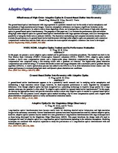
Fig. 1 Compact adaptive optics system being installed on onemeter telescope at the Naval Observatory Flagstaff station.
of the telescope optics train to calibrate the system using a standard NOFS camera. The AO system was then reinstalled. The system was mounted on an 18⫻ 24 in., .75-in. thick aluminum plate. The optics resides on top of the plate while the power supply, control electronics, and computer are mounted to the bottom of the plate. Vibration from the computer’s hard-disk driver was suppressed by wrapping it in a vibration damping foam. The optical design was optimized for a compact system using ZEMAX. The adaptive element used in this experiment was a MEM 37-element mirror5 from OKO technologies 共Delft, The Netherlands兲.6 The unit is 15 mm in diameter and was
driven with custom electronics to drive each actuator with 0 to 140 V providing a “throw” of approximately 40 waves 共at 633 nm兲 for focus and about 2-1 / 2 waves for higher order corrections. The DM and schematic of the MEM mirror are shown in Fig. 2. The wavefront sensor was a Shack-Hartman7 lenslet array coupled to a 128⫻ 128 pixel CCD camera from Dalsa. The maximum allowed frame rate for such a camera and readout electronics is approximately 750 frames per second. The camera readout noise, especially at high frame rates, was the limiting factor for the sensitivity of the system. Combined with the poor seeing conditions, due in large part to high clouds on the one available night during the run, the performance of the Dalsa in this mode required actual frame rates to be around 100 Hz. For a brief period during the observing run, the weather cleared enough to close the loop on the bright star Vega. The telescope itself presented a challenge to the wavefront reconstruction algorithm. The pupil of the telescope has a 45% central obscuration due to the secondary mirror. This is quite a large obscuration for standard meter class telescopes. 60 subapertures were used for wavefront sensing. The wavefront reconstructor required at least three subapertures between the inner and outer radii. Figure 3 shows both the pupil and the images formed by the subapertures. The 45% obscuration by the secondary is evident in both images.
Fig. 2 Photo and schematic of OKO deformable mirror used in the described adaptive optics system. This unit has 37 active elements and measures 15 mm in diameter. Custom electronics drove the actuators.
J. Microlith., Microfab., Microsyst.
041504-2
Oct–Dec 2005/Vol. 4共4兲
Restaino et al.: Experimental results of a MEMS-based adaptive…
Fig. 4 Time sequence of four subapertures from the ShackHartman wavefront sensor.
The Shack-Hartman measurements and data processing7 are illustrated in Eqs. 共1兲 and 共2兲. ⌬x =
R n x
⌬y =
R , n y
Fig. 6 Average stellar image: 共a兲 open loop and 共b兲 closed loop.
共1兲
s = 关B兴 + n,
共2兲
= 关B1CnB兴−1关BT兴关Cn兴−1s.
共3兲
Equation 共1兲 represents the slope measurements made by a Shack-Hartmann sensor. Equation 共2兲 is the signal equation of the wavefront sensor, where the matrix B is the reconstructor matrix and n represents the noise. The least square approach to invert Eq. 共2兲 is shown in Eq. 共3兲 under generic assumptions, i.e., that we can use a covariance matrix to describe the noise contribution Cn, etc. This traditional reconstruction scheme, however, has difficulties with missing data, especially when they are dynamically changing, like in the case of scintillation. However, with our new algorithm, the reconstructor is not vulnerable to effects from large obscurations and the effects of scintillation. This was one of the reasons that we elected to observe in the middle of the monsoon season in Flagstaff, Arizona, to evaluate the effects of scintillation on our new reconstructor algorithm. The new algorithm will be the object of a forthcoming publication. Measurements of scintillation index were carried out using the wavefront sensor data. The scintillation index 共for definition and properties, see for example Ref. 8兲 is typi-
cally around 20% and for very good seeing conditions, it is of only a few percent. Figure 4 shows a 3.5-s time sequence of four subapertures. The measured scintillation index, averaged over the subpupils, is shown in Fig. 5. The analysis of Figs. 4 5, and 6 illustrates the amount of scintillation that the reconstructor had to cope with. Notwithstanding such dynamical changes in the number of illuminated subapertures, as can be clearly seen in the video in Fig. 6, the reconstructor was able to allow closed-loop operations. 3 Results and Discussion Scintillation and poor seeing decreases the stability of the wavefront reconstruction, since the variation in intensity makes for large differences in the signal-to-noise ratio from one subpupil to another. Cloud cover made observations logistically challenging. Images of Vega using open- and closed-loop corrective optics are shown in Figs. 6共a兲 and 6共b兲. The images are 30-s integrations. The closed-loop point spread function 共PSF兲 is symmetric and the central peak is much higher. A scan through the vertical axis of Fig. 6 is shown in Fig. 7 and the scale is in counts, after bias and dark correction, of the CCD camera. The time averaged open-loop Strehl ratio was about 3.7%, and the closed-loop Strehl ratio was 27%, showing a factor of 6 in improvement, even with the difficult conditions. Figure 8 shows a single frame nontime averaged, open loop and closed loop of Vega. The instantaneous Strehl ratios are 2.9 and 21%, respectively.
Fig. 5 Scintillation index versus time.
J. Microlith., Microfab., Microsyst.
Fig. 7 Cross-cur of the two PSF shown in Fig. 6.
041504-3
Oct–Dec 2005/Vol. 4共4兲
Restaino et al.: Experimental results of a MEMS-based adaptive…
4. 5. 6. 7. 8.
perimental results of a MEM based adaptive optics system,” Proc. SPIE 5348, 160–165 共2004兲. NOFS 1m Telescope, see http://ftp.nofs.navy.mil/about_NOFS/ telescopes/rc.html. L. Zhu, P. Sun, D. Bartsch, W. Freeman, and Y. Fainman, “Adaptive control of a micromachined continuous-membrane deformable mirror for aberration compensation,” Appl. Opt. 38, 168–176 共1999兲. OKO homepage, see http://www.okotech.com/. R. K. Tyson, Principles of Adaptive Optics, Academic Press, San Diego, CA 共1991兲. F. Roddier, “The effects of atmospheric turbulence in optical astronomy,” Prog. Opt. 19, 281–376 共1981兲.
Sergio R. Restaino received his MS 共equivalent兲 in physics from the University of Naples 共Italy兲 in 1986, and his PhD in optics from the University of Florence 共Italy兲 in 1989. He is currently with the remote sensing division at the Naval Research Laboratory. His research interests are in the area of high angular resolution imaging, with a special emphasis on novel adaptive optics techniques and wavefront sensing. Before joining the Naval Research Laboratory, he was with the Air Force Research Laboratory, Directed Energy Directorate. G. Charmaine Gilbreath received her BS in physics from Georgia Institute of Technology in 1982, her MSE in electrical engineering, and PhD from The Johns Hopkins University in 1986 and 1989, respectively. She has been with the Naval Research Laboratory 共NRL兲 since 1982. Her specialties are in nonlinear optics, free-space optical data transfer, and optical device development. She is the lead principal investigator for NRL’s multiple quantum well retromodulator
Fig. 8 Single frame loop closed and open.
4 Summary and Conclusion The first test run of a portable adaptive optics system is performed. Mounting of the instrument, alignment, and closing of the loop on the system is accomplished in less than two days. Weather prevented substantial testing; however, the cloud cover opened long enough to close the loop on Vega. Examples of this data are presented with a 4- to 6-fold increase in Strehl. The work shows that successful demonstration of the instrument concept and design is achieved. Important parameters such as size, weight, and ease of installation as well as performance are also important for applicability to interferometry, where installation on a number of telescopes is needed to obtain viable images. We show that the compact system can be installed quickly on a one-meter telescope and produce viable images, even in challenging weather conditions.
programs.
References 1. Adaptive Optics in Astronomy, F. Roddier, Ed., Cambridge Press, Cambridge, MA 共1999兲. 2. Adaptive Optics for Industry and Medicine, S. R. Restaino and S. W. Teare, Ed., Albuquerque 共2002兲. 3. S. R. Restaino, G. C. Gilbreath, D. T. Payne, and J. Andrews, “Ex-
J. Microlith., Microfab., Microsyst.
041504-4
Don M. Payne received his BS in astronomy from the University of Kansas in 1986, and his BS in computer science from the University of Kansas in 1988. He founded Narrascape, Incorporated, in 2002, and has worked in the imaging, dynamic optics, and space surveillance community since 1993. His specialties are real-time control algorithms and complex system modeling and development. He is President and Chief Analyst at Narrascape. Jonathan R. Andrews received his BS in electrical engineering from the New Mexico Institute of Mining and Technology in 2003. He is currently finishing his MS in electrical engineering from the same school. His interests include adaptive optics, wavefront sensing, and electronic control theory. He has been working with the Remote Sensing Division of the Naval Research Laboratory since 2002.
Oct–Dec 2005/Vol. 4共4兲