support real-time computer interconnections for image and data communications. Index Termsâ Optical code-division multiplexing, optical en- coder and ...
368
IEEE JOURNAL OF SELECTED TOPICS IN QUANTUM ELECTRONICS, VOL. 5, NO. 2, MARCH/APRIL 1999
Experiments on High-Speed All-Optical CodeDivision Multiplexing Systems Using All-Serial Prime Code Encoders and Decoders for Jian-Guo Zhang, Member, IEEE, Lian-Kuan Chen, Member, IEEE, Wing C. Kwong, Senior Member, IEEE, Kwok-Wai Cheung, Senior Member, IEEE, and A. B. Sharma, Senior Member, IEEE
Abstract— In this paper, we demonstrate experimental alloptical code-division multiplexing (AO-CDM) systems using 64-ps optical pulses and a 2n prime code of n = 3. A distinguishing feature of this experiment is that the modulation of ultrashort optical clock stream by electrical data is realized without using any optical intensity modulator at each transmitter. Moreover, only low-cost standard optical 2 2 2 couplers and fiber delay lines are employed to implement all-serial encoders and decoders for a 2n prime code. As a result, this new system is more cost- and power-effective than a conventional AO-CDM system. Furthermore, the use of AO-CDM systems can offer parallel communications over a common fiber channel, which in turn can support real-time computer interconnections for image and data communications. Index Terms— Optical code-division multiplexing, optical encoder and decoder, optical fiber communications, optical signal processing, optical transmission systems.
I. INTRODUCTION
S
INGLE-MODE optical fibers can provide an usable transmission bandwidth of 25 THz in the 1.55- m wavelength window, which can support ultrahigh-speed data transmission and networking applications. However, the use of electronic signal processing ultimately limits the data throughput. To eliminate the throughput bottleneck, optical signal processing should be employed in ultrahigh-speed optical fiber systems where such functions as data sampling, multiplexing, transmission, amplification, and demultiplexing (also possibly including data regeneration) are performed completely in the optical domain. In doing so, this in turn can support ultrafast signal processing with a speed up to 100 Gb/s [1]–[3]. Therefore, future high-speed communication systems will be based on optically processed architectures. In recent years, optical code-division multiplexing (CDM) techniques have been receiving considerable attention [1]–[9]. Experimental demonstrations of high-speed optical CDM systems have been also reported [2]–[6]. Optical CDM, as an alternative to optical time-division and wavelength-division Manuscript received December 17, 1998; revised April 19, 1999. J.-G. Zhang and A. B. Sharma are with the Telecommunications Program, School of Advanced Technologies, Asian Institute of Technology, Pathumthani 12120, Thailand. L.-K. Chen and K-W. Cheung are with the Department of Information Engineering, The Chinese University of Hong Kong, Shatin, N.T., Hong Kong. W. C. Kwong is with the Department of Engineering, Hofstra University, Hempstead, NY 11550 USA. Publisher Item Identifier S 1077-260X(99)06057-8.
multiplexing, is attractive for high-speed local area networks (LAN’s) because many users can simultaneously transmit data messages over a common fiber channel [2]. This characteristic of parallel communications can be substantially utilized to support real-time computer interconnections for high-speed image and data communications. As we know, using optical orthogonal codes (OOC’s) with cross-correlation constraint of 1 and autocorrelation constraint of 1 can achieve better bit-error-rate (BER) performance than employing other in all-optical CDM (AO-CDM) address codes of systems [7]. Note that the value “1” is the minimum correlation constraint for incoherent optical signal processing [3], [7]. However, the complexity of code generation/correlation and the power loss of all-optical encoder–decoder must be also taken into account when we design AO-CDM systems. codes in AOA recent study has shown that employing CDM systems can result in simple encoder and decoder using an all-serial structure, which requires a far smaller number of optical components and has lower optical power loss than using conventional all-parallel encoder–decoder [2]. This is pulses in any codeword because the second half of the is just the delayed replica of the pulses in the first half and is the code weight of this codeword, where (i.e., the number of pulses per codeword). This characteristic can be utilized to significantly simplify the optical encoder and decoder by using an all-serial configuration shown in Fig. 1 optical couplers are required [2], where only codeword. In contrast, for generating or correlating any an optical encoder (or decoder) with the parallel configuration optical couplers for a given code comprises (see Fig. 2), which is bulky and has a high weight so that it may not be power loss for a large value of implementable (e.g., when equals several tens or hundreds). In the ideal case, the total coding and decoding power loss code is equal to dB if the encoder–decoder for a dB if pair in Fig. 1 is used, while the total power loss is the encoder–decoder pair in Fig. 2 is employed. Furthermore, the all-serial structure can be implemented by using a silicabased planar lightwave circuit to further reduce the power loss and to guarantee a precise time delay, as will be discussed codes derived from prime subsequently. In particular, those codes are very attractive to AO-CDM applications, because their encoding/decoding algorithms are systematical and are very simple (i.e., modulo multiplication) [8], [9].
1077–260X/99$10.00 1999 IEEE
ZHANG et al.: EXPERIMENTS ON HIGH-SPEED AO-CDM SYSTEMS
369
Fig. 1. All-serial configuration of an all-optical encoder or decoder.
Fig. 2. All-parallel configuration of an AO-CDM encoder or decoder.
In this paper, we report a new experiment on high-speed prime code. Unlike conventional AO-CDM systems using AO-CDM systems [2]–[6], in our experiment no any optical intensity modulator is used at each transmitter to gate the ultrashort optical clock pulses by electrical data. Moreover, only couplers and fiber delay lines low-cost standard optical are employed to implement all-serial encoders and decoders prime code. Therefore, this new system is more costfor a and power-effective than a conventional AO-CDM system. II. PRINCIPLE
AND
EXPERIMENTAL SET-UP
Let be a prime number. A prime code of length and weight is derived from a set of prime sequences , where -Galois modulo [3]. A prime code with field, and distinct codewords, for , are thus constructed by [3] and otherwise.
where is an integer and . and , For all of a prime code is obtained from the valid codeword , and satisfying [8] (4) . where Using (4), we can find that all the codewords of the prime can be modified to form a prime code code with , code length , and code size 11 (i.e., the with total number of users). In this section, we demonstrate two-user AO-CDM systems. In the experiment, the used codewords are the zeroth codeword prime code with and the third codeword of the and (i.e., code weight 8)
(1)
prime code with cross-correlation constraint A is obtained from the prime code of , by selecting only pulses (per codeword) that satisfy the specific delaythe and any integers , , , distribution constraint: For any , , , and and , such that , if and are divisible by , then we have [8]
and
(2) , where the “ ” in (2) for a given integer denotes modulo- addition, and the adjacent relative cyclic delays ’s are defined as [8] for for (3)
We assume that the data rate of users is equal to 100 is then equal to Mbit/s. The slot width (i.e., unit delay) picoseconds (ps). This data rate has been adopted by the data-communication standards, such as Fiber Distributed Data Interface (FDDI) and fast ethernet, to support computer interconnections for data and image communications.
370
IEEE JOURNAL OF SELECTED TOPICS IN QUANTUM ELECTRONICS, VOL. 5, NO. 2, MARCH/APRIL 1999
Fig. 3. Experimental setup for simulating two-user AO-CDM communication systems.
Fig. 4. Optical pulse from a gain-switched DFB LD.
Fig. 3 shows the experimental set-up for simulating twouser AO-CDM communication systems. At the transmitting end, 100-MHz electrical clock signal from a BER tester is amplified first, so that it can drive a 100-MHz HP comb generator of which the output signal is added to the 100-Mb/s electrical data at a power combiner. Then a DFB laser diode (LD) at the 1.55- m wavelength is driven by a current signal containing three components (see Fig. 3), namely, a dc prebias, a data current pulse, and a clock pulse. By correctly setting prebias and data currents, the DFB LD is biased just below a threshold at which the gain switching occurs. Thus, the LD is gain switched only if a data pulse and a clock pulse are simultaneously present to make the carrier concentration above the threshold [10]. In this way, ultrashort optical clock signal is effectively modulated by electrical data bits at the LD, without using any optical intensity modulator. In doing so, it not only can reduce the complexity and cost of an AO-CDM transmit-
ter, but also can eliminate the insertion power loss associated with using an optical intensity modulator (e.g., about several dB). Consequently, cost-effective AO-CDM transmitters can be realized by using this scheme, whereas the conventional AO-CDM transmitter must use an optical intensity modulator to on–off modulate the optical clock pulse stream [2]–[6]. Then the resulting optical pulse is fed into all-optical encoder to and 3). For a codeword of generate codeword ( , the all-serial encoder (or decoder) comprises only passive optical 2 2 couplers that are serially connected with each other by 3 fiber delay lines and 3 reference fibers (assumed to have 0 delay) as shown in Fig. 1 [2], where ps, ps, ps for and ps, ps, ps for . Note that both delay-line and reference fibers are only pigtail optical fibers of commercially available 2 2 optical couplers. In contrast, a -code encoder (or decoder), if using an
ZHANG et al.: EXPERIMENTS ON HIGH-SPEED AO-CDM SYSTEMS
371
(a)
(b) Fig. 5. (a) Electrical data bit “1” (with ECL logic) and the optical pulse sequence encoded with sequence encoded with C3 .
C0 .
Fig. 6. Electrical bit stream “10 001” (with ECL logic) and the resulting pulse sequences encoded with
all-parallel structure [2], requires 14 optical 1 2 couplers, 7 delay-line and 1 reference fibers, as shown in Fig. 2. It is clear that using the all-serial structure can efficiently reduce cost, complexity and power loss of optical encoders–decoders, especially for a large value of . Furthermore, the use of integrated optics can allow us to feasibly implement power-efficient,
(b) Electrical data bit “1” and the optical pulse
C0 .
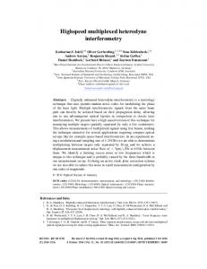
waveguide-integrable all-serial encoders and decoders. This in turn can facilitate applications of AO-CDM systems. By using a HP high-speed digital oscilloscope, the 64ps width of gain-switching optical clock pulses is directly measured at the output of a 45-GHz photodetector, as shown in Fig. 4. Normally, a gain-switched laser diode suffers both
372
Fig. 7. Measured autocorrelation of
IEEE JOURNAL OF SELECTED TOPICS IN QUANTUM ELECTRONICS, VOL. 5, NO. 2, MARCH/APRIL 1999
C0 .
(a)
(b) Fig. 8. (a) Measured cross correlation of
C0
with
C3 . (b) Measured cross correlation of C3
timing jitter and frequency chirping, but they can be reduced by injecting a narrow linewidth continuous-wave (CW) light into the gain-switched laser diode. The CW light of narrow linewidth can be obtained from an external tunable optical source. An electrical NRZ data bit “1” (with ECL logic) from the BER tester is illustrated as the upper traces in Fig. 5(a) and
with
C0 .
(b), respectively. The corresponding codewords and from two optical encoders are then shown as the lower traces in Fig. 5(a) and (b), respectively. Fig. 6 shows the complete electrical data bits “10 001” (upper trace) at the input of a gain-switched LD and the resulting pulse sequences for (lower trace). Although commercially available low-cost 2 2 optical couplers (with splitting ratios of 2.8 dB/3.2 dB and 2.9
ZHANG et al.: EXPERIMENTS ON HIGH-SPEED AO-CDM SYSTEMS
373
Fig. 9. Schematic diagram of a proposed AO-CDM encoder (or decoder) using silica-based PLC [14].
dB/3.1 dB) are used in the encoders and decoders, the optical pulse sequence of nearly constant amplitude is obtained for , by using couplers of splitting ratio 2.9 dB/3.1 dB and carefully fusing pigtail fibers between two couplers in series. In the experiment, we can control the delay-time error of fiber delay lines within 17 ps as measured for , only by carefully cutting and fusing the pigtail fibers of couplers. For the pulse sequence of , unequal pulse amplitudes are visible [see the couplers with lower trace in Fig. 5(b)], because optical worse ratio (2.8 dB/3.2 dB) are used at this encoder such that the accumulated amplitude error is more severe. This also suggests that using a silica-based planar lightwave circuit should achieve the low power loss, uniform splitting ratio, and very precise time delay for all-serial encoders–decoders, as will be discussed subsequently. Because of symmetric pulse codeword, decoder is the same as distribution in each and 3. encoder for the codeword , where is measured at the output of The autocorrelation of decoder 0, which has a main peak of 8 (i.e., code weight 8) and the highest sidelobe of 7 as shown in Fig. 7, because is of a repetition code. The cross correlation of with is shown in Fig. 8(a). There is no surprise to observe that with , shown in Fig. 8(b), is the the cross correlation of with . These are also confirmed by the same as that of computed cross correlations. III. DESIGN CONSIDERATION The use of discrete optical 2 2 couplers and fiber delay lines can implement AO-CDM encoders and decoders as described in the above. This simple approach, however, has some disadvantages. For example, the resulting encoder and decoder normally have a relatively large size and low reproducibility. To fabricate them, special attentions are paid to fiber alignment, length adjustment/control, and fiber splicing, which in turn lead to the unavoidable splice power loss and time-delay error in the manufacture process. Moreover, the achievable precision in control of fiber lengths may prevent such encoders and decoders from ultrahigh-speed operations. To overcome these difficulties, monolithic integration of optical passive couplers with delay lines is highly required. As known, integrated optics or planar waveguide technology has played an important role in the fabrication of lightwave circuits due to the reasons of manufacturability and economy.
Fig. 10. Schematic diagram of an erbium-doped silica-based planar waveguide amplifier [17].
With this technology, integrated-optic components can be implemented lithographically, resulting in the potential of low cost for mass production. Planar waveguides are light paths that are carefully fabricated as a region of increased refractive index within some low-loss transparent substrate material or upon such a substrate [11]. In particular, silica-on-silicon technique is very promising for integrated optics. This is because: 1) the fabrication process is cheap and compatible with that used for silicon-based microelectronics; 2) the connection to single-mode optical fibers may be achieved with low loss and cost; 3) a wide range of low-loss passive components may be easily fabricated on large substrates; and 4) some active devices such as optical amplifiers can be constructed [12]. Silica-based planar lightwave circuits (PLC’s) are very suitable for integrated AO-CDM encoders and decoders because of low loss (e.g., less than 0.1 dB/cm [11]) and compactness. Moreover, they can have high reproducibility and low coupling loss to optical fibers (e.g., 0.05 dB) [12], [13]. Silicabased PLC’s have been already employed as an ultrahighspeed time multiplexer in all-optical time-division multiplexing (AO-TDM) systems with a speed up to or beyond 100 Gb/s [14]–[16]. Here we can use a similar structure, i.e., a Mach–Zehnder interferometer (MZI) chain, to design an AOCDM encoder (or decoder) with silica-based PLC, as shown in Fig. 9. The device comprises low-loss silica waveguides and directional couplers on a silicon substrate. The difference between the proposed encoder (decoder) and the reported time multiplexer is only due to the selections of different delay times for a MZI chain. This is achieved by carefully choosing a specific length difference between two arms in each MZI.
374
Fig. 11.
IEEE JOURNAL OF SELECTED TOPICS IN QUANTUM ELECTRONICS, VOL. 5, NO. 2, MARCH/APRIL 1999
Configuration of a proposed AO-CDM system using integrated optics and optoelectronic integrated circuits.
Since the use of integrated silica-based waveguides can guarantee a high precision in length control, this makes waveguide delay lines not only compact but also have a more accurate delay time compared with using their fiber-optic counterpart. For example, silica-based PLC’s have achieved an accuracy of delay time being better than 15 fs [16]. This in turn can support ultrafast signal processing above 1 Tb/s. Moreover, the coupling ratios of the couplers in each MZI can be controlled by thin-film heaters [14]. In doing so, it can guarantee uniform splitting ratios for couplers, and therefore, constant-amplitude optical pulse stream can be generated. As reported in [15], the 50-Gb/s time-multiplexed optical pulse stream has been generated by using a silica-based PLC, having almost equal pulse amplitude and accurate time interval between optical pulses. Recently, an erbium-doped silica-based planar waveguide amplifier has been demonstrated with a net gain of 27 dB, and it has been integrated with a directional coupler to multiplex the signal and pump lights [17]. In the waveguide amplifier, erbium-doped silica-based waveguides were fabricated on a silicon substrate by flame hydrolysis deposition and reactive ion etching [17], [18], as shown in Fig. 10. Moreover, with planar waveguide technology, such an erbium-doped waveguide amplifier can be further integrated with a passive AO-CDM encoder or decoder (see Fig. 9) on the same silicon substrate to make the encoder or decoder subsystem more compact and suitable for mass reproduction at low cost. Monolithic integration can also eliminate the coupling loss at each fiberdevice interface. For practical applications, the input and output fibers must be connected to such silica-based PLC’s in order to make the system work. Moreover, it is highly desirable that fiber-to-PLC connection should have a low cost and allow mass production. To achieve this aim, V-grooves can be used to efficiently connect PLC’s to optical fibers with the potential low cost, by preferential etching and direct implementation on the silicon-supported integrated optic components [19]. It is
also advantageous if the waveguide and alignment features are fabricated on a common substrate [12]. For example, fiber-toPLC connection can be implemented by using V-grooves on the silicon substrate. As shown in Fig. 3, all the electronic circuits at an optical transmitter can be implemented by employing mature IC techniques that have been already used in radio and wireless communications. It is because, compared with optical pulses of a few tens of picoseconds, the electrical signal which is used to gain switch the laser diode normally has a much larger pulsewidth (e.g., a few hundred picoseconds or even larger). Moreover, a laser diode can be monolithically integrated with a V-groove to enable passive alignment with the optical fiber [20]. The use of this monolithic approach can result in the reduction of assembly time and size required for pigtailed lasers. On the other hand, InP–InGaAs double-heterojunction bipolar transistors (DHBT’s) can be monolithically integrated with p-i-n photodetectors to realize wide-band optical receivers that can support a transmission speed up to 40 Gb/s [21]. It is expected that either monolithic integration or hybrid integration can be applied to fabricate a high-speed optical CDM receiver containing the DHBT-based decision circuit [22]. Therefore, the configuration of the proposed AO-CDM system using integrated optics and optoelectronic integrated circuits (OEIC’s) is illustrated in Fig. 11. IV. CONCLUSION In this paper, we have reported the design of new AO-CDM prime code of systems using 64-ps optical pulses and a . In principle, 11 users can be accommodated with data rate up to 129 Mb/s if we assume that the slot width is equal to 64 ps. This data rate can support FDDI and fast ethernet applications. Since no optical intensity modulator is required at each transmitter and only low-cost optical 2 2 couplers are used to implement the all-serial encoder–decoder, both
ZHANG et al.: EXPERIMENTS ON HIGH-SPEED AO-CDM SYSTEMS
cost- and power-effective AO-CDM systems can be realized. Furthermore, the lossless AO-CDM encoder (and decoder) can be implemented by using the silica-based PLC integrated with an erbium-doped silica waveguide amplifier of 27-dB gain [17]. This can make encoders and decoders compact. For practical applications, the input and output fibers must be connected to such silica-based PLC’s. To achieve this aim, V-grooves can be used to efficiently connect PLC’s to optical fibers. We have also discussed the feasibility of using integrated optics and OEIC’s to implement the proposed systems. Since the use of AO-CDM systems can offer parallel communications over a common fiber channel, this in turn can support real-time computer interconnections for image and data communications. ACKNOWLEDGMENT The authors would like to thank the anonymous reviewers for useful comments and suggestions. REFERENCES [1] P. R. Prucnal, M. A. Santoro, and S. K. Sehgal, “Ultrafast all-optical synchronous multiple access fiber networks,” IEEE J. Select. Areas Commun., vol. SAC-4, pp. 1484–1493, Dec. 1986. [2] W. C. Kwong and P. R. Prucnal, “Ultrafast all-optical code-division multiple-access (CDMA) fiber-optic networks,” Computer Networks and ISDN Systems, vol. 26, no. 6, pp. 1063–1086, 1994. [3] P. R. Prucnal, M. A. Santoro, and T. R. Fan, “Spread spectrum fiber-optic local area network using optical processing,” J. Lightwave Technol., vol. LT-4, pp. 547–554, May 1986. [4] R. M. Gagliardi, A. J. Mendez, M. R. Dale, and E. Park, “Fiber-optic digital video multiplexing using optical CDMA,” J. Lightwave Technol., vol. 11, pp. 20–26, Jan. 1993. [5] A. J. Mendez, J. L. Lambert, J.-M. Morookian, and R. M. Gagliardi, “Synthesis and demonstration of high speed, bandwidth efficient optical code division multiple access (CDMA) tested at 1 Gb/s throughput,” IEEE Photon. Technol. Lett., vol. 6, pp. 1146–1149, Sept. 1994. [6] G. J. Pendock, M. J. L. Cahill, and D. D. Sampson, “Multi-gigabit per second demonstration of photonic code-division multiplexing,” Electron. Lett., vol. 31, no. 10, pp. 819–820, 1995. [7] F. R. K. Chung, J. A. Salehi, and V. K. Wei, “Optical orthogonal codes: Design, analysis, and applications,” IEEE Trans. Inform. Theory, vol. 35, pp. 595–604, May 1989. [8] W. C. Kwong and G.-C. Yang, “Construction of 2n prime-sequence codes for optical code division multiple access,” Proc. Inst. Elect. Eng.—Commun., vol. 142, no. 3, pp. 141–150, 1995. [9] W. C. Kwong, J.-G. Zhang, and G.-C. Yang, “2n prime-sequence code and its optical CDMA coding architecture,” Electron. Lett., vol. 30, no. 6, 1994. [10] Y.-C. Lu, P. Zhou, and J. Cheng, “A directly modulated pulsecompressed and time-multiplexed optical source for high-speed multiple-access networks,” IEEE Photon. Technol. Lett., vol. 5, pp. 905–907, Aug. 1993. [11] P. E. Green, Jr., Fiber Optic Networks. Englewood Cliffs, NJ: PrenticeHall, 1993. [12] R. R. A. Syms, “Silica-on silicon integrated optics,” Lecture Notes, Int. School of Quantum Electron., Erice, Italy, June 1993.
375
[13] Y. Hibino, F. Hanawa, H. Nakagome, N. Takato, T. Miya, and M. 8 splitters on Si,” Yamaguchi, “High reliability silica-based PLC 1 Electron. Lett., vol. 30, no. 8, pp. 640–642, Apr. 1994. [14] K. Uchiyama, H. Takara, S. Kawanishi, T. Morioka, M. Saruwatari, and T. Kitoh, “100 Gbit/s all-optical demultiplexing using nonlinear optical loop mirror with gating-width control,” Electron. Lett., vol. 29, no. 21, pp. 1870–1871, Oct. 1993. [15] S. Kawanishi, H. Takara, K. Uchiyama, T. Kitoh, and M. Saruwatari, “100 Gbit/s, 50 km, and nonrepeated optical transmission employing all-optical multi/demultiplexing and PLL timing extraction,” Electron. Lett., vol. 29, no. 12, pp. 1075–1077, June 1993. [16] E. Yamada, E. Yoshida, T. Kitoh, and M. Nakazawa, “Generation of terabit per second optical data pulse train,” Electron. Lett., vol. 31, no. 16, pp. 1342–1344, Aug. 1995. [17] K. Hattori, T. Kitagawa, M. Oguma, Y. Ohmori, and M. Horiguchi, “Erbium-doped silica-based waveguide amplifier integrated with a 980/1530 nm WDM coupler,” Electron. Lett., vol. 30, no. 11, pp. 856–857, May 1994. [18] T. Kitagawa, K. Hattori, K. Shuto, M. Yasu, M. Kobayashi, and M. Horiguchi, “ Amplification in erbium-doped silica-based planar lightwave circuits,” Electron. Lett., vol. 28, no. 19, pp. 1818–1819, Sept. 1992. [19] G. Grand, H. Denis, and S. Valette, “New method for low cost and efficient optical connections between singlemode fibers and silica guides,” Electron. Lett., vol. 27, no. 1, pp. 16–18, Jan. 1991. [20] M. A. Rothman, C. L. Shieh, A. J. Negri, J. A. Thompson, C. A. Armiento, R. P. Holmstrom, and J. Kaur, “Monolithically integrated laser/rear-facet monitor arrays with V-groove for passive optical fiber alignment,” IEEE Photon. Technol., vol. 5, pp. 169–171, Feb. 1993. [21] E. Sano, K. Sano, T. Otsuji, K. Kurishima, and S. Yamahata, “Ultra-high speed, low power monolithic photoreceiver using InP/InGaAs doubleheterojunction bipolar transistors,” Electron. Lett., vol. 33, no. 12, pp. 1047–1048, June 1997. [22] M. Yoneyama, E. Sano, S. Yamahata, and Y. Matsuoka, “17 Gbit/s pin-PD/decision circuit using InP/InGaAs double-heterojunction bipolar transistors,” Electron. Lett., vol. 32, no. 4, pp. 393–394, Feb. 1996.
2
Jian-Guo Zhang (S’93–M’93), photograph and biography not available at the time of publication.
Lian-Kuan Chen (S’85–M’86), photograph and biography not available at the time of publication.
Wing C. Kwong (S’88–M’92–SM’97), photograph and biography not available at the time of publication.
Kwok-Wai Cheung (S’82–M’86–SM’92), photograph and biography not available at the time of publication.
A. B. Sharma (S’72–M’75–SM’98), photograph and biography not available at the time of publication.