opment of knowledge-level frameworks for the construction of expert systems. We have ... lary for explanation of the problem solving activity and the rationale for the conclusions made ...... In addition we would like to thank John. Josephson ... 6] B. Chandrasekaran, J. R. Josephson, A. M. Keuneke, and D. Herman. Building ...
M. C. Tanner, A. M. Keuneke, and B. Chandrasekaran, "Explanation Using Task Structure and Domain Functional Models," Second Generation Expert Systems, eds., J. M. David, J. P. Krivine, and R. Simmons, Springer-Verlag, 1993, pp. 599-626.
Explanation in Knowledge Systems: The Roles of the Task Structure and Domain Functional Models� B. Chandrasekarany Anne M. Keunekez Michael C. Tannerx For a number of years, a group of us have been concerned with the development of knowledge-level frameworks for the construction of expert systems. We have emphasized analysis at the level of the tasks, what characterizes the goals that need to be achieved, what kinds of methods are useful for achieving them, and what kinds of knowledge are needed to implement the methods. We have shown that this perspective is helpful in many ways: to separate the essential role knowledge plays in the achievement of problem solving goals from the symbol systems in which they are represented, to provide a vocabulary for the analysis of tasks and subtasks which in turn can provide a road map for knowledge acquisition, to provide a framework for modularization and implementation of knowledge system using high level languages whose terms are closer to the task that is faced by the knowledge engineer, to provide leverage points for learning, and, nally, to provide a vocabulary for explanation of the problem solving activity and the rationale for the conclusions made by the knowledge system. In our Laboratory, we have also been in parallel working on a new approach to representing causal understanding how devices work. Speci cally, we have proposed that the bottom-up component behavior-composition picture that emerges from the current work in qualitative device simulation � This paper is the culmination of series of papers on this topic. Earlier versions have appeared in some form in IEEE Expert and several books. y Department of Computer and Information Science, The Ohio State University z Computer Science Department, California State University, Chico x Computer Science Department, George Mason University
1
2 needs to be complemented by a top-down function-oriented organization of causal process description. We have also been developing concrete proposals about what one might call the logic of causal process descriptions, and how the functional view helps to bridge the state descriptions at the component level with appropriate abstractions at the device level. This work, which we have called Functional Representations, has helped us to provide clari cations for a number of phenomena in knowledge-based reasoning: the relation between what has been called compiled knowledge and deep knowledge, how diagnostic task-speci c compiled knowledge can be derived from functional models of the device that is being diagnosed, and, relating to the topic of this paper, how explanations of diagnostic conclusions can be given partly by constructing causal accounts of how the symptoms are caused by the proposed diagnoses. In this paper we survey our perspective on how knowledge systems can be built that provide good explanations. The rst part of the paper presents an analysis of the explanation problem and the aspects of it that we have concentrated on (brie y, we are concerned more with the form and content of the representations than the explanation form or presentation). Then we describe a generic task-based approach to explanation, including relating the explanation to the logical structure of the task. Finally, we show how causal models of a domain can be used to give explanations of diagnostic decisions.
1 Aspects of Explanation As described by Chandrasekaran, Tanner, and Josephson [8], we can separate the explanation generation problem in knowledge systems into three top-level functions: generating the content, being responsive, and interacting with human users. Generating an explanation's basic content. Given user queries about a system's decisions, we need to generate an information structure containing the elements needed for an explanation. Shaping explanations to match user knowledge. It may not be necessary to communicate all the available explanation content to users. Systems apply knowledge of user goals, state of knowledge, and the
3 dialog structure to lter, shape, and organize the output of the above content process so that explanations respond to user needs. Interacting with users. The two preceding functions produce all the information needed conceptually and logically for the required explanation. However, presentation issues remain; speci cally, how an appropriate human-computer interface e�ectively displays and presents information to users. If explanation content is inadequate or inappropriate|no matter how good theories for responsiveness and interface functions are|then correspondingly poor explanations will be presented. Thus, generating the correct explanation content is the central problem in explanation generation. We can break this down into the following types: Step explanation. Relating portions of the data in a particular case to the knowledge for making speci c decisions or choices, i.e., explaining the steps in the solution process. Strategic explanation. Relating decisions to follow particular lines of reasoning to the problem solver's goals. Task explanation. Relating the system's actions and conclusions to the goals of the task it performs. Knowledge justi cation. Relating conclusions and problem-solving knowledge to other domain knowledge, possibly showing how they were obtained. These four kinds of explanation are related to the act, or process, of solving problems. A knowledge system might be asked questions about many other relevant things, including requests for de nition of terms and exam-like questions that test the system's knowledge. Answers to these questions may or may not be explanations, as such, but a knowledge system should still be able to produce them. All of these kinds of explanation correspond to structures that must be examined when constructing explanations, even though some of the structures may not be needed to solve problems in the system's domain. Often explanations are produced by introspection, i.e., a program examines its own knowledge and problem-solving memory to explain itself.
4 Step and strategic explanations are most often done this way. But sometimes explanations are concocted, i.e., they do not relate to how the decision was actually made, but independently make decisions plausible. Constructing such post facto justi cations or explanations is necessary when problem solvers have no access to their own problem solving records, or when the information contained in those records is incomprehensible to users. The explanation may argue convincingly that the answer is correct without actually referring to the derivation process, just as mathematical proofs persuade without representing the process by which mathematicians derive theorems. Task explanations and knowledge justi cations are often done this way. Generating explanations of this sort is an interesting problem solving process in its own right [22, 39].
2 Tasks, Methods and Explanations In this section we give a brief outline of the notion of a task analysis as developed by Chandrasekaran [4]. Explaining a knowledge system's solutions requires, among other things, showing on one hand how the logical requirements of the task were satis ed by the solution and, on the other hand, showing how the method adopted (the strategy) achieved the task in the problem-solving instance. In principle there may be more than one method for a task. Most knowledge systems have \hard-wired" speci c methods for the tasks. Thus Mycin can be understood as solving the diagnostic task by the method of heuristic classi cation, which in turn performs the subtasks of data analysis, heuristic match, and re nement [9]. In the generic task (GT) framework, developed at Ohio State, we have identi ed a number of task-method combinations that can be used as building blocks for more complex tasks. Thus, for example, the task of diagnosis is associated with a generic method called abductive assembly, which in turn sets up a subtask of hypothesis generation. In our GT work, a generic method called hierarchical classi cation is proposed for exploring certain types of hypothesis spaces. This in turn sets up subtasks for evaluating hypotheses in the hierarchy for which a generic method called hierarchical evidence abstraction is proposed. What we have called GTs are in fact task-method combinations. The method is particularly appropriate to the task because it is commonly used in many domains for that task and it gives signi cant computational advantages. Two
5 of the GTs we have identi ed are Hierarchical Classi cation and Design by Plan Selection and Re nement.1
Hierarchical Classi cation Task: If a hypothesis hierarchy is available, generate hypotheses that
match the data describing a situation. Method: For each hypothesis, set up a subtask to establish or reject it. If it is established, test its successors. If it is rejected, it and its successors are rejected. The top-down control strategy, called Establish-Re ne, can be varied under speci c conditions. Bylander and Mittal [2] elaborate on this simpli ed account.
Design by Plan Selection and Re nement Task: Design an object that satis es certain speci cations. Method: Design is separated into a hierarchy of subdesign problems,
mirroring the object's component structure. For each node in the hierarchy, there are plans for making commitments for some component parameters. Each component is designed by choosing a plan, based on some speci cations, which instantiates some design parts and designs further subcomponents to ll in other parts. We describe this task in more detail in Section 3, but Brown and Chandrasekaran [1] is the de nitive reference on this topic. Each GT method is explicitly supported by a high-level language that aids knowledge system development by giving the knowledge engineer access to tools that work closer to the problem level, not the rule or frame level. However, it may be necessary to divide non-trivial problems into subproblems such that each matches some GT. This way of building complex knowledge systems also means that knowledge engineering environments should provide a tool set rather than a single tool. Consequently, some of our recent work has concentrated on developing the Generic Task Toolset [21]. In using the GT theory for explanation we need to show how the methodspeci c high-level language helps in explicitly and directly generating explanations of strategy at the right level. This is what our early work involved, 1 The following description di�ers from descriptions in earlier papers [3], since we have separated the task and the method explicitly.
6 and is described in Section 3. In general, however, we also need to relate the logical structure of the task to the strategy employed. Issues involved in this are discussed in Section 4. Then in Sections 5 and 6 we describe work on justifying problem-solving knowledge by reference to the more general knowledge on which it is based.
3 Generic Tasks and Explanation|An Example GTs make strategic explanation possible for systems built using this theory [8]. Additionally, any explanation facility should be able to explain the steps a problem solver takes in reaching a solution. In this section we describe MPA (a Mission Planning Assistant) [18], a GT program capable of explaining its problem-solving steps and its strategy. We transferred the techniques developed on this system to the Generic Task Toolset [21] so that any system built using those tools could explain its steps and strategy. MPA is a GT implementation of Knobs [13], a system that plans a particular kind of Air Force mission.2 The type of planning required can be viewed as design, i.e., designing the plan. So we used the GT of Design by Plan Selection and Re nement, and implemented MPA using the generic task tool DSPL (Design Specialists and Plans Language) [1].
3.1 Overview of DSPL
A design problem solver in DSPL is a hierarchy of specialists, each responsible for a speci c design portion (see Figure 1). Specialists higher up in the hierarchy deal with the more-general aspects of devices being designed, while specialists lower in the hierarchy design more-speci c subportions. The organization of the specialists, and the speci c content of each, is intended to capture design expertise in the problem domain. Each specialist contains design knowledge necessary to accomplish a portion of the design (see Figure 2). Each specialist has several types of knowledge but, for simplicity, we will describe only three. First, explicit design plans in each specialist encode sequences of possible actions to successfully 2
MPA actually implements a very simpli ed version of the problem.
7
OCA
�Q � Q � Q � Q � Q � Q � Q � QQ �
Base
Aircraft
J
J J
Conf. F-111
Conf. F-4
J J J
Conf. A-10
Figure 1: Organization of MPA, a DSPL Problem Solver
8
Aircraft Default Selector
� � � A A A
� Sponsor �
A-10
A-10 Plan
F-4 Sponsor
F-4 Plan
A F-111 A Sponsor
F-111 Plan
Figure 2: Inside a DSPL Specialist complete that specialist's task. The plans consist of design steps, each of which chooses a value for one parameter of the design. Second, specialists have design plan sponsors associated with each plan to determine that plan's appropriateness in the runtime context. And third, each specialist has a design plan selector to examine runtime judgments of sponsors and to determine the plan most appropriate to the current problem context. In a DSPL system, control proceeds from the topmost design specialist to the lowest. Each specialist selects a plan appropriate to the problem's requirements. The system executes plans by performing design actions that the plan speci es (which may include computing and assigning speci c values to device attributes, checking constraints, or invoking subspecialists to complete another portion of the design).
3.2 Description of MPA
In MPA the top-level specialist is OCA (for O�ensive Counter Air, the type of mission MPA works on), which has design plans for producing the mission plan. Subcomponents of the mission are the Base and the Aircraft (see Figure 1). The Base specialist chooses the air base (actually a list of bases) using the requirements of the mission. The Aircraft specialist chooses an aircraft type, and then con gures the aircraft for the mission using subspecialists. As an example of a specialist, consider Aircraft (shown in Figure 2). It
9 (PLAN (NAME A-10) (SPONSOR A-10-Sponsor) (PURPOSE ``considering the feasibility of an A-10 for the mission'') (ACHIEVED ``chose an A-10 for the mission'') (BODY AssignAircraftType ChooseSquadron AssignBase GetRange (DESIGN Configure-A-10)))
Figure 3: MPA's A-10 Plan contains a selector, in this case it is the default selector built into DSPL. The default selector simply chooses the best plan, according to ratings assigned by the sponsors, and if there are no good plans it fails.3 Aircraft also contains three sponsors, one for each of its plans. It has a plan for each aircraft type (A-10, F-4, and F-111). The DSPL code for Aircraft's A-10 Plan is given in Figure 3. MPA decides whether A-10 is the appropriate aircraft type for the mission using its sponsor-selector mechanism described above. If A-10 is appropriate, this plan is executed. The BODY contains a list of the steps in the plan. It rst notes the aircraft type, then chooses a squadron. The base is determined from the chosen squadron and then the range to the target is computed. Finally, the aircraft is con gured for the mission (bomb and fuel load) by calling the subspecialist Con gure-A-10. One of the steps, ChooseSquadron, is shown in Figure 4. Steps in DSPL set the value of a single design attribute, so the step rst identi es the attribute it sets (SQUAD). The DSPL functions KB-FETCH and KB-STORE fetch and store attribute values of the design. The KNOWN section of the body is a facility for de ning local variables for known attributes. REPLY contains the main work of the step. In this case the REPLY simply stores an attribute value but, in general, it could do more work to decide on the value. The DSPL contains a mechanism, not described here, for dealing with failures. Brown and Chandrasekaran [1] provide the details. 3
10 (STEP (NAME ChooseSquadron) (ATTRIBUTE-NAME SQUAD) (PURPOSE ``selecting a squadron for the mission'') (ACHIEVED ``selection of & as the squadron for the mission'') (BODY (KNOWN plane (KB-FETCH AIRCRAFT) base-list (KB-FETCH BASELIST)) (REPLY (KB-STORE SQUAD (squad-select plane base-list))
Figure 4: MPA's ChooseSquadron Step Lisp function squad-select implements the expert's method of choosing a squadron given the aircraft type and bases available. Since this is done in a Lisp function, it will not be easily explainable. A better implementation of MPA would include this decision process in DSPL, rather than in Lisp. In the end, MPA produces a list of attributes for the mission with the values it decided upon. For example: Aircraft Type A-10 Number of Aircraft 4 Squadron 118TFW Airbase Sembach ... ... This list is actually a menu, from which users can select any value and ask MPA to explain how that value was decided.
3.3 Explanation in MPA
We implemented explanation in MPA on the organizing principle that the agent that makes a decision is responsible for explaining it. For our purposes, we consider the things we have described|specialists, selectors, sponsors, plans, and steps (Figures 2{4)|to be problem-solving agents in DSPL. The current implementation of MPA contains nearly 100 of these agents, which
11 The context of considering the feasibility of an A-10 for the mission determined that: � plane was A-10 � base-list was Ramstein, Bitburg, Sembach So 118TFW was an appropriate choice for Unit.
Figure 5: Explanation for a Step call upon each other during the problem-solving process. All of these agents have well-de ned roles, so the system can explain an agent's decisions in terms of the goals of its calling agent, the agent's own role in the pursuit of those goals, and the roles of other agents it called upon. To do this we added slots called PURPOSE and ACHIEVED to the agent de nitions in DSPL to hold text strings for describing the agents' goals. Then to explain how MPA decided on a particular attribute value, the explanation module puts these strings together in an order that depends on the runtime context in which the decision was made. Given such an explanation users can select any of the other agents and ask for further elaboration from them. Suppose a user selected the value \118TFW" of the attribute \Unit". The only question users can ask MPA, the only explanation it can give, is a form of \How was it decided?" Thus, the user's selection in this case implicitly asks, \How was it decided that the Unit should be 118TFW?" The explanation is given in Figure 5. This decision was made by the ChooseSquadron step so the explanation comes from that agent. The explanation rst gives the purpose of the calling agent (shown in italics), which comes from the A-10 plan in this case. Then it gives the values of the local variables. Finally, it gives the value it chose for its attribute. This explanation may be unsatisfying. A better explanation in this case might be: Assuming that we are to use A-10s and that the only bases available are Ramstein, Bitburg, and Sembach, then 118TFW is the only unit that ies A-10s out of these bases. Some of the di�erence between this and Figure 5 is the quality of the English text. The only content di�erence, and content has been our focus, is in connecting the assumptions (values of local variables) to the nal decision. MPA could do this better if the nal decision were made using DSPL rather
12 The context of considering the feasibility of an A-10 for the mission determined that: � plane was A-10 � base-list was Ramstein, Bitburg, Sembach � units-with-A10 was 118TFW So 118TFW was an appropriate choice for Unit.
Figure 6: Improved Explanation for a Step than the Lisp function squad-select. A slightly improved version of the explanation would appear as in Figure 6. Because the explanation module is essentially just translating DSPL code into text, the quality of the programming a�ects the quality of the explanation. This is a little bit undesirable but also unavoidable in a system that has to explain itself using only its own problem-solving knowledge. Users can select any of the local variables given in the explanation (i.e., plane and base-list) for further elaboration. For example, to nd out why plane is A-10. This would result in getting an explanation from another step, since attribute values are determined by steps. Or users can select the calling agent for further explanation. This would result in an explanation from the A-10 plan, shown in Figure 7. As with the step explanation, the context comes from the calling agent, the Aircraft specialist here. The bulleted items are the purposes from the called agents. Additionally, the explanation shows where the agent was in its procedure. In this explanation, since the user arrived here from the ChooseSquadron step, the plan had completed the AssignAircraftType step, was in the process of doing the ChooseSquadron step, and had yet to do the AssignBase and GetRange steps and complete the con guration. The explanations shown here are generated from explanation templates. Each agent type has a standard representation form from which we derived its explanation template. A simpli ed version of the standard form for plans is shown in Figure 8 (the simpli cation is that in addition to steps, plans can contain DESIGN calls to subspecialists as in Figure 3). Figure 9 shows a correspondingly simpli ed explanation template for plans, assuming that it is entered from step i. Thus, a plan's explanations are put together out of the goals of its calling specialist and the goals of the steps it calls.
13
In the context of selecting an appropriate aircraft for the mission I: � Assigned A-10 as the aircraft type. I was in the process of: � Selecting a squadron for the mission. and was about to do to following: � Select a base for the mission. � Determine the range for the mission. � Choose a con guration for the A-10 on this mission.
Figure 7: Explanation for a Plan
(PLAN (NAME hplan namei) (SPONSOR hsponsor namei) (PURPOSE hpurpose stringi) (ACHIEVED hachieved stringi) (BODY hstep 1i .. . hstep ii .. . hstep ni))
Figure 8: Standard Plan Representation
14 Putting explanations together out of \canned" text, the way MPA does, is not a very sophisticated method of text generation. However, the important point here is that the roles of the various agents|specialists, plans, steps, etc.|and their relationships de ne the kinds of things that can be said and how these things go together to make sensible explanations. These roles and relationships are de ned by the GT, in this case Design by Plan Selection and Re nement. We have more work to do on developing a taxonomy of PURPOSEs for the various agents, and then showing how to use the taxonomy for explaining. However, our aim for MPA was to demonstrate that GT programs provide the structures needed to generate explanations of strategy and steps.
15 In the context of hpurpose of containing specialist i I: � hachieved string from step 1i . � ..
� hachieved string from step i ; 1i
I was in the process of: � hpurpose string from step ii and was about to do to following: � hpurpose string from step i + 1i . � ..
� hpurpose string from step ni
Figure 9: Plan Explanation Template
4 Explanation Based on the Logical Structure of a Task GTs combine tasks with appropriate methods, which enables explanations to show how strategic elements combine to achieve the task's major goals. However, as described by Chandrasekaran [4] (see Section 3), for any task there are many possible methods. To properly explain how a program's knowledge, strategy, behavior, and conclusions relate to its problem-solving task, we need to separate the task's requirements from those of the methods that perform it. For example, one diagnostic goal is to nd a disease that explains the symptoms. One method would produce explanatory hypotheses using disease hierarchies, another would produce them using causal models. Each method imposes its own requirements and has a distinctive behavior, but both serve the same diagnostic subgoal|generating explanatory hypotheses. An explanation should relate their behavior to their subgoal in spite of the detailed di�erences between them. So it is important to identify tasks' logical structure, independent of particular solution methods, to be used in designing explanation components for systems that perform them. In this section we describe Tanner's work on task explanation in diagnosis [36].
16
4.1 The Logical Structure of Diagnosis
Diagnosis is usually considered an abduction problem [12, 17, 20, 28, 29, 30]. That is, the task is to nd a disease, or set of diseases, that best explains the symptoms. Accordingly, a diagnostic conclusion is supported, perhaps implicitly, by the following argument: � There is a principal complaint, i.e., a collection of symptoms that sets the diagnostic problem. � There are a number of diagnostic hypotheses that might explain the principal complaint. � Some of the diagnostic hypotheses can be ruled out because they are: (1) unable to explain the principal complaint in this instance, or (2) implausible independent of what they might explain. � The diagnostic conclusion is the best of the plausible hypotheses that are capable of explaining the principal complaint. This argument form is the logical structure of the diagnostic task. It can be thought of as a means of justifying diagnoses. As such, it suggests speci c ways a diagnostic conclusion might be wrong. Suppose the diagnostic conclusion turns out to be wrong. What happened to the true answer? That is, why did the true, or correct, answer not turn out to be the best explanation? Based on the logical structure of diagnosis, given above, the diagnostic conclusion can only be wrong for one or more of the following reasons: 1. There is something wrong with the principal complaint. Either it is (1) not really present or does not need to be explained, or (2) incomplete, there are other things that should be explained by the diagnostic conclusion. 2. The true answer was not on the list of diagnostic hypotheses thought to have the potential of explaining the principal complaint. 3. There is an error in ruling out. (a) The true answer was ruled out. It was mistakenly thought (1) to be implausible or (2) not to explain the data.
17 (b) The wrong answer (the one given) was not ruled out. It was mistakenly thought (1) to be plausible or (2) to explain the data. 4. There is an error in choosing the best of the plausible explanations. Either (1) the wrong answer appears to be better than it is, or (2) the true answer appears to be worse than it is. The source of these errors might be found in either missing or faulty knowledge as well as in various problems with the data itself. Many users' questions can be interpreted as attempts to ensure that the conclusion is correct. Thus, corresponding to each source of potential error there is a class of questions, each seeking reassurance that a particular kind of error was not made. This analysis tells us that if we build a knowledgebased system and claim it does diagnosis, we can expect it to be asked the following kinds of questions. 1. Is the principal complaint really present or abnormal? 2. Does the principal complaint contain all the important data? 3. Was a broad enough set of explanatory hypotheses considered? 4. Has some hypothesis been incorrectly ruled out? 5. Could some hypothesis explain a nding that the system thought could not? 6. Was some hypothesis not ruled out that should have been? 7. Is it possible that the hypotheses in the diagnostic conclusion do not really explain the ndings? 8. Might the hypotheses in the diagnostic conclusion be rated too high? 9. Has some hypothesis been underrated? Furthermore, these questions express the only reasonable concerns that arise solely because it is a diagnosis system. We are not suggesting that all questions will be in exactly one of these classes, some may refer to many of these concerns, others are not speci cally about diagnosis.
18 User: What antibody in the conclusion explains the following test result: (164 Coombs 3+) Red: The nding: (164 Coombs 3+) is explained by: antiS
Figure 10: An Explanation From Red
4.2 Using the Logical Structure for Explanation
Any diagnostic system will have some means of achieving the diagnostic goals speci ed in the logical structure given above. Otherwise it will fail, in some respect, to be a diagnostic system. The diagnostic question classes are derived from the diagnostic goals, so the rst step in building an explanation component is to map the diagnostic question classes onto the program. That is, each question class (say, \Is it possible that the hypotheses in the diagnostic conclusion do not really explain the ndings?") is mapped onto the the part of the system responsible for achieving the corresponding goal (in the example, the part that determines the symptoms a diagnostic hypothesis explains). This way the questions can be answered by the part of the system that made the relevant decisions to explain how the decision helps achieve the goal. In order for this to work, the explainer needs a way of mapping users' questions into the appropriate question classes. Let us brie y consider an example from a diagnostic system called Red. In order to give blood to patients who need it, a hospital blood bank must select compatible donor blood. A part of this decision involves nding out what antibodies a patient has. Red is a system that aids in this antibodyidenti cation problem. This is a kind of diagnostic problem since the data is a set of test results to be explained and the antibodies are used to explain them. One type of question that people ask of Red is what antibody in Red's conclusion explains a particular test result. This question is an instance of the question class de ned by: \Is it possible that the hypotheses in the diagnostic conclusion do not really explain the ndings?" This is derived from the potential error that the answer given does not actually explain the
19 data. This, in turn, is derived from the diagnostic goal of explaining the data. So the question (\What explains a particular test result?") is directed to the component of Red that chooses antibodies to explain particular elements of data. It produces an explanation such as the one in Figure 10. The \(164 Coombs 3+)" is the notation for a test result and \antiS" is shorthand for \antibody to the S antigen". This process of mapping the question to the part of the system that can answer it is not done automatically in Red. The logical structure of diagnosis was used in building Red's explanation component, but the mapping is hard-coded in the program. Tanner [36] describes explanation for Red in more detail while Red itself was fully reported by Josephson, et al. [20] The logical structure of diagnosis presented here is a common view of the diagnostic task [12, 17, 20, 28, 29, 30]. Not all approaches to diagnosis will share this view. In fact, there is one common competing view|diagnosis as description, i.e., the goal of diagnosis is to describe the patient's state, not to nd a cause for the symptoms. But if users and systems agree to a logical structure, it can be used to develop explanation for diagnosis in the manner we describe. The details will change if the model changes, but the method, and the idea, of using the logical structure to develop explanations remains.
5 Knowledge Justi cation: Relating Problem Solving to Causal Models The integration and use of causal models in compiled problem-solving systems has become increasingly prevalent. Xplain was probably the rst system to provide explanations of problem-solving knowledge by showing how it was obtained by compilation from other knowledge about the domain [26, 35]. Our work on functional representations (FR) [31] is similar in showing how to compile diagnostic programs from functional representations of mechanical devices. Following on this, Keuneke's work [22] showed how to use FR for justifying diagnostic conclusions, which we describe in this section.
5.1 Background
Methods that carry out problem-solving tasks need knowledge of certain kinds and in particular forms. For example, establish-re ne, a method for
20 hierarchical classi cation, requires knowledge relating descriptions of situations to descriptions of classes (see Section 2). If knowledge is not available in this form, it must be derived from some other knowledge. We refer to this derivation process as compilation [31, 35, 15], and to knowledge in the desired form as compiled knowledge [7]. The \other knowledge" has sometimes been called deep knowledge, but it is not necessarily deeper or better, only less compiled relative to the method that needs it. The compiled knowledge can be justi ed by referring to the knowledge from which it was compiled. As with any compiled knowledge, compiled diagnostic knowledge can be justi ed by referring to the compilation process. Diagnosis also admits an interesting variation on this type of justi cation. If a system for diagnosing faults in a mechanical device is compiled from a causal model of the device, then its diagnostic conclusions can be related to observations using the causal model. This justi es the conclusion and validates the compiled knowledge that produced it. The causal model could be used to perform diagnosis, and systems have been built that do this [11, 27, 38], but for complex devices the large amount of causal information makes the diagnostic task very di�cult. In most diagnostic systems, the causal knowledge is compiled for greater expertise and optimum diagnostic performance. Then, if a causal story can be put together, using the hypothesized diagnostic answer as a focus, we get the advantages of both worlds: the computational bene ts of compiled knowledge to obtain the diagnostic answer, as well as the causal model to validate it. In a diagnostic context, given the symptoms and the diagnostic conclusion, Keuneke showed how to use a causal model to justify the diagnosis at various levels of detail. In many situations a similar method will work to justify individual rules in the knowledge base. Wick [39] developed a related idea: justifying a conclusion in terms of the standard arguments used by domain experts. Both Wick and our work using FR produce justi cations by reference to knowledge not used, perhaps not even needed, to produce the solution. However, one important di�erence is that justi cations come from knowledge that, in principle, could be used to compile diagnostic problem solvers while Wick is not committed to any particular relationship between justi cation knowledge and problem-solving knowledge. The intent of Keuneke's [22] research was to continue e�orts in the development of a deviceand domain-independent representation capable of modeling the core aspects of device understanding; the extended goal is a cognitive model of device un-
21 derstanding. Although this work was driven by the task of explanation, the representation was designed to provide the basic primitives and organization for a variety of problem-solving tasks.
5.1.1 The Functional Representation
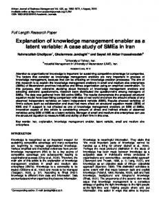
Initial e�orts to generate causal justi cations [5, 6, 18, 25] focused on enhancing Sembugamoorthy and Chandrasekaran's FR [31] to provide a representation with the necessary organization and primitives4 . Functional Representation is a representational scheme for the functions and expected behavior of a device. FR represents knowledge about devices in terms of the functions that the entire device is supposed to achieve and also of the sequence of causal interactions among components that lead to achievement of the functions. FR takes a top-down approach to representing a device, in contrast to the bottom-up approach of behavior-oriented knowledge representation and reasoning schemes [10, 14]. In FR, the function of the overall device is described rst and the behavior of each component (its causal process) is described in terms of how it contributes to the function5. Figures 11 and 12 illustrate the top-level representation of a chemical processing plant. In this representation, a device's function is its intended purpose. Functions describe a device's goals at the device level. For example, the function of a chemical processing plant is to produce a certain product. It has components for supplying the reactants, stirring the substance, extracting the product, and so forth. But generating the product is a function of the device as a whole. Functions are achieved by behaviors or causal processes. In the chemical processing plant example, the substance is produced by the causal sequence of (1) input of the reactants into the reaction vessel, (2) allowing reactant contact, and then (3) extracting the product from the reaction vessel. In short, the functions are what is expected; the behaviors are how this expected result is attained. In FR, behaviors are represented as causal sequences of transitions between partial states or predicates (e.g., (present reactants rxvessel)). For a more current formal treatment of the representation, see [19] A function's causal process is represented in the machine by its causal process description { CPD. 4 5
22 ControlLiquidFlow controlamount LiquidFeedSystem reactantsupplied ControlLiquidTemp controlheat PressureControlSystem PressureCtrl
TransferSystem extraction SolidConcCtrl ChemProcPlant produce.acid
ControlAirFlow controlflow
AirFeedSystem ControlAirPressure controlpressure airsupply bubblemix bubblesuspension ControlAirTemp controltemp CoolingSystem cool Condenser condense cool2 CondensateWithdrawalSystem LiquidConcCtrl retrieveliquid
Sensor produce.signal
CoolantSystem providecoolant heattransfer
MixingSystem mix suspension
Figure 11: Functional Component Hierarchy The device is represented at various levels. The topmost level describes the functioning of the device by identifying which components and more detailed causal processes are responsible for bringing about the various state transitions. If a transition is achieved using a function of a component, the next level describes the functioning of this component in terms of the roles of its subcomponents, and so on. Ultimately, either by tracing through more detailed causal processes or by expanding the causal processes of functional components, all the functions of a device can be related to its structure and the function of the components within this structure.
5.1.2 Enhancing the Functional Representation Early explanation work [5] simply used the FR as a tool to answer questions such as: (1) Why is this device needed? (2) What subcomponents does this device require? (3) What does this function accomplish? (4) Why or where is this function used in the device? (5) How is this function achieved? Later, enhancements to the FR allowed the representation of state and
23 (amount acid below.threshold) By SupplyReactants
(present reactants rxvessel) By ReactantContact
(occurred reaction rxvessel) AsPer exothermic.reaction.se
(amount heat rxvessel increased) By: CompensateOxidation.se
AsPer: products.replace.reactants
(present acid rxvessel) UsingFunction extraction of TransferSystem
(condition rxvessel sufficient)
(present product external.container)
Figure 12: CPD oxidation for Function produce.acid of a Chemical Processing Plant behavior abstractions [24, 22]. Abstract schema speci cations, and the ability to make transitions between abstraction levels, is useful for providing di�erent levels of explanation. For example, suppose there exists a solid/liquid mixture in which action is being taken to keep the solid from the bottom of the container. One might witness the following causal loop: by stirring ||||||{i (solid falls) (solid rises) h||||||{ by gravity Here an observer could follow the loop any number of times, but somewhere one takes a conceptual jump and identi es the dynamic process (solid fall, solid rise, solid fall, solid rise...) as a state at a di�erent behavioral level, i.e., identi cation of the process state (solid suspended). In doing so, one is identifying a new phenomenon; the observer is packaging a process and seeing it from a higher conceptual viewpoint. These types of conceptual transitions are commonplace in one's understanding of a device's behavior | especially in cyclic or repeated behaviors. Nevertheless, past methods of behavior abstraction (detail suppression) did not explicitly address the representation of such phenomenon.
24 For researchers interested in building models of devices solely to predict behavior at a given level of detail, these abstractions will not be helpful. Instead, these abstractions provide the ability to tell a higher level story. Prediction is not driven solely by constraints of structure and low-level processes, but can be enriched and focused by knowledge of abstract processes and the inferences they dictate. Additional enhancements include establishing a taxonomy of function types. Each function type indicates di�erent procedures for simulation, di�erent functional capabilities, di�erent expectations, and thus di�erent knowledge speci cations for representation and explanation. Function types include: 1. ToMake: achieves a speci c partial state 2. ToMaintain: achieves and sustains a desired state 3. ToPrevent: keeps a system out of an undesirable state 4. ToControl: gives a system power to regulate changes of state via a known relationship. More details on the knowledge distinguishing each type, explicit speci cations of the function types, and the information processing distinctions each type makes is provided in [22, 23]. The structure of the functional representation, organized around functional packages, provides focus through which simulation and the identi cation of structural cause can be determined (i.e., given changes in function, what changes in structure could be hypothesized to account for them?). Since, at some level, most problem-solving tasks dealing with devices are concerned with either the achievement of function, or consequences of the failure to achieve function, a functional description and reasoning power proves useful. The use of the representation in diagnosis seems especially appropriate since diagnosis centers around determining the change in structure that resulted in some malfunction.
25
6 Causal Explanation: The Problem Statement To illustrate the use of the representation, we pose the following problem: Given a set of observations and a diagnostic hypothesis, attempt to construct an explanation in the form of a causal story which starts with a diagnostic hypothesis and ends with one or more of the observations to be explained. In the following, we examine how a functional representation can be used for this purpose. Technical de nitions of a few terms may be useful: Observations: observable states, including a subset which are malfunctions of the device subsystems or components. The following distinctions about observations are useful: � Symptoms: abnormal states which are indicative of malfunctions and trigger the diagnostic process, e.g., speci cation of a drop from normal pressure. � Malfunctions: observations which are malfunctions, e.g., speci cation of a faulty pressure regulator. Malfunction observations are generally also symptoms. � Observable states which provide information about the device but do not directly correspond to abnormalities, e.g., speci cation of temperature or pressure readings. Typically in a complex system, a large number of observations are used in the diagnostic process which provide focus for the problem-solving but do not necessarily indicate problems (e.g., sensor readings). Diagnostic Hypotheses: the set of malfunctioning components or missing (but expected) relationships between components. Each in the latter should sooner or later, manifest itself as the malfunction of a subsystem within which the components lie. Causal Explanation: Normally one expects a diagnosis to causally \explain" the symptoms, even though in general the diagnosis actually should explain all the observations. The explanation provided here takes any given set of observations to be explained and tries to propose a causal path from the diagnostic hypothesis to these observations.
26 The explanation sought can be formally stated as follows: diagnostic hypothesis ! x1 : : : ! xi : : : ! xN where each xi is either (1) an internal state which is causally relevant in producing an observation, but is itself not a malfunction, (2) a component or subsystem malfunction, or (3) an observation at the device-level. The explanation system developed in this work produces explanation chains where the members are limited to the last two, i.e., malfunctions or observations, unless the causally relevant internal state has been provided explicitly as a state that needs to be explained, i.e., as input to the casual explanation system.
6.1 Generating the Malfunction Causal Chain
In the same way a functional representation provides an organization to allow simulation of how expected functionalities are achieved, it can also serve as a backbone to trace the e�ects of not achieving certain functions | thus identifying potential malfunctions. The organization of a functional representation gives both forward and backward reasoning capability, i.e., it can trace from the hypothesized malfunction to the observed malfunctions and symptoms (forward), or it can trace from observed malfunctions to the hypothesized malfunction (backward). Because both the observations and the diagnostic hypotheses have been identi ed once diagnosis is complete, the functional representation could potentially be used to perform either form of control. This section provides an algorithm which demonstrates the forward simulation potential6 . Speci cally, if device A is malfunctioning, then devices which use device A (say devices B and C) have a high probability of malfunctioning as well. Similarly, devices which use B and C may malfunction, etc. The malfunction causal chain is achieved through the following algorithm which has been condensed to illustrate main points. 1. { Set Observations to the symptoms and malfunctions to be explained, { Set MalfunctionList to the hypothesized malfunction set provided by 6 Note that since the explanation generation mechanism uses expected functionalities and their causal processes rather than all behaviors that could possibly be generated, the problem space is bound and thus focused.
27
2. 3.
4.
5. 6. 7.
the diagnosis, { Initialize MalfunctionObject to an individual malfunction in this set (diagnosed hypotheses and their relationship to observations are considered individually) Find all functions which made use of the function which is malfunctioning (MalfunctionObject), call this set PossibleMalfunctions, For each element in PossibleMalfunctions (call the speci c function PossMal) consider the signi cance of the e�ect of MalfunctionObject on the function. � if no e�ect on PossMal then remove from PossibleMalfunctions | MalfunctionObject is not causing future problems. Consider the next element in PossibleMalfunctions. � else maintain (Malfunction ! Malfunction) explanation chain; MalfunctionObject is now known to cause a malfunction to PossMal. Speci cally MalfunctionObject ! PossMal is appended to chain. Note that this step will ultimately place any potential malfunctions in a malfunction chain, including those which are in the set of Observations. Continue. Check the states in the causal process description of the a�ected PossibleMalfunction. Would noncompletion of these states explain any symptom(s) in Observations? � if yes, append to ExplainedSymptoms and print the chain which led to this symptom. Complete the malfunction explanation chain by continuing. Set MalfunctionObject to PossMal. (MalfunctionObject (= PossMal) Repeat process from step 2 until all symptoms are in ExplainedSymptoms or the top level causal process description of the device has been reached. The Process from step 1 is repeated until all elements of MalfunctionList have been considered.
28 Step 2 is easily accomplished through the component hierarchy of the functional representation (example in Section 6.2). Step 3 and 4 are more intricate and involve knowledge of function type and the achievement of the intended causal processes. For example, in step 3, to determine the e�ects of a malfunction on other functions, one must consider the possible consequences of malfunctioning components. In general, the malfunction of a component in a device can cause one or more of the following three consequences: NOT Function: expected results of the function will not be present. Given that the malfunction is not producing the expected results within the causal process, what states in those causal processes will not occur, and will lack of this functionality cause the malfunctions of functions in which the malfunctioning component was used? Parameter Out-of-Range: expected results of the function are a�ected, but behavior is still accomplished to a limited degree. Sometimes components may be considered malfunctioning yet can still perform the behavior (or value of some substance parameter) to the extent needed for future use. New Behaviors: the malfunction results in behaviors and states which were not those intended for normal functioning. The determination of whether a proposed malfunction can explain a symptom, step 4 in the explanation algorithm, can be established by a number of means: 1. Check each state in the causal process description where the malfunctioning component is used to see if there is a direct match between a symptom and not achieving an expected state. 2. Check to see if the function which is malfunctioning has an explicit malfunction causal process description and if the symptom is included therein. 7 See [22] for knowledge of function type and detail on functions with explicit malfunction causal processes. 7
29 3. Check to see if side e�ects of the functions causal process description refer to the symptoms. 4. Check each state in the malfunction causal process description and its provided clause to see if expected states point to general concepts or generic classes of behavior (such as leak, ow, continuity) and if the symptom pertains to or is explained by such concepts. 5. If the malfunction is a malformation, i.e., the malfunction is described as a malformation of a particular physical component, perform deep reasoning (e.g., qualitative physics) to see if malformation could cause the symptom. The rst three are implemented and currently used for the explanation generation; the means to perform the last two are research in progress.
6.2 Representation of a Chemical Processing Plant
This section provides the output for an example explanation in the domain of Chemical Processing Plants. Reference to Figure 11 (in Section 5.1.1) will assist the reader in following the causal explanation chains given by the algorithm. The hierarchy in Figure 11 shows a partial representation of the functional components with their intended functions (functions are speci ed under component names). The top level function, produce.acid,8 is achieved by the causal process oxidation shown in Figure 12. It should be noted that the function hierarchy is generated given the causal processes used to achieve functions of the functional component. For example, the Chemical Processing Plant uses the functional components LiquidFeedSystem, AirFeedSystem, TransferSystem, etc. in the process oxidation which represents the causal chain used to achieve the function produce.acid; the TransferSystem uses the functional components AirFeedSystem, MixingSystem, etc. in its causal process to achieve the function extraction, and so on. 8
The acid produced is a solid, terephthalic acid.
30
6.2.1 The Problem The Coolant System (identi ed at the right of Figure 11 ) is used to provide coolant water to a Condenser so that it can be used to transfer heat from the vapor in the Condenser (see Figure 13). Suppose the coolant water has been completely cut o�. A diagnostic system has concluded that a malfunction of the function provide.coolant of the Coolant System explains the symptoms of NOT (present product external.container) and NOT (temperature rxvessel at.threshold). Speci cally, MalfunctionObject is fprovide.coolant of Coolant Systemg and the Observations to be explained are fNOT (present product external.container), NOT (temperature rxvessel at.threshold) g. The system produces the following three casual stories.
6.2.2 Causal Story 1: Generation of Causal Connections The causal process SupplyReactants uses the functions retrieveliquid and LiquidConcCtrl, in addition to the LiquidFeedSystem and AirFeedSystem. The explanation system generates the following: The symptom NOT (present product external.container) is explained by the following chain: NOT provide.coolant causes malfunction in condense causing malfunction in retrieveliquid causing malfunction in LiquidConcCtrl causing problems in behavior SupplyReactants which is used in behavior oxidation and indicates malfunction of the top level function and results in NOT (present product external.container) --The following symptoms are not explained: NOT (temperature rxvessel at.threshold)
The idea here is that if the required amount of reactants is not available, the product is not produced as desired and thus can not be retrieved. The explanation system generates this chain by using the following information:
31 (present vapor condenser) UsingFunction:provide.coolant of CoolantSystem
(surrounded vapor coolant) UsingFunction:heat.transfer of CoolantSystem
(temperature vapor decreased) AsPer:heat.transfer/condensation at dewpoint
(condensed vapor condenser) AsPer: Identity
(present liquid condenser)
Figure 13: CPD: RemoveHeat of Function Condense Provide.coolant caused a malfunction in condense because it caused a failure in condense's behavior. A malfunction in condense caused a malfunction in retrieveliquid because its achievement was required to attain the desired behavior for retrieveliquid. Retrieveliquid caused a malfunction in LiquidConcCtrl because it was needed to provide the preconditions for LiquidConcCtrl and it preceded the use of LiquidConcCtrl in the behavior SupplyReactants. SupplyReactants was used in the causal process Oxidation, Figure 12, to achieve the state (present reactants rxvessel). This state was necessary for the completion of the behavior and thus non-achievement here denotes nonachievement of further states in the behavior, particularly NOT (present product external.container).
6.2.3 Causal Story 2: The Use of Side E�ect Inspection The explanation system continues and nds a causal connection for the second symptom, NOT (temperature rxvessel at.threshold). The symptom NOT (temperature rxvessel at.threshold) is explained by the following chain: NOT provide.coolant causes malfunction in condense causing problems in behavior removeheat of function cool
32 Since cool is not a top level function of the chemical processing plant, the trace continues until all consequences are determined. The symptom NOT (temperature rxvessel at.threshold) is explained by the following chain: NOT provide.coolant causes malfunction in condense causing malfunction in cool causing problems in behavior compensate.oxidation.se a notable side effect behavior used in oxidation and indicates NOT (temperature rxvessel at.threshold) --The following symptoms are not explained (present product external.container)
Notice that this explanation identi es that the symptom was observed in a side e�ect behavior (compensation for e�ects of the reaction) rather than a behavior of the main functionality (production of acid). The statement of which symptoms are not explained indicates those that were not explained in the speci c causal chain. A nal statement is made when the system has inspected all pertinent causal chains (as seen in the next causal story).
6.2.4 Causal Story 3: Using Subfunction Connections for Causal Focus
The nal causal path is achieved via causal connections obtained speci cally through the knowledge of subfunctions. In its speci cation, the function extraction has a provided clause which speci es that the solid acid slurry must have the proper consistency so that ow through the extraction tube is possible. The function SolidConcCtrl is present in this device for the sole purpose of producing these conditions for extraction. The purpose of SolidConcCtrl is to keep the solid suspended and the concentration in the reaction vessel at the proper consistency. In the CondensateWithdrawalSystem, the retrieveliquid function uses the Condenser to
33 retrieve the condensate from the vapor produced. The MixtureLevelCtrl function then uses a feedback controller to maintain the ow and thus the desired amount of liquid in the reaction vessel | which ensures that the acid slurry has the proper consistency. If the liquid is not retrievable, then obviously the condensate ow cannot be controlled and consistency of the acid in the vessel is not maintained. The explanation system provides this explanatory story as follows: One function affected by provide.coolant is SolidConcCtrl which is a necessary subfunction of extraction The symptom NOT (present product external.container) is explained by the following chain: NOT provide.coolant causes malfunction in condense causing malfunction in retrieveliquid causing malfunction in MixtureLevelCtrl causing malfunction in SolidConcCtrl causing malfunction in extraction causing malfunction in produce.acid causing NOT (present product external.container) --All symptoms have been explained.
6.3 Discussion
The intrinsic limitations of a functional representation for explanation arise from its intrinsic limitations for simulation. The representation uses prepackaged causal process descriptions which are organized around the expected functions of a device. Simulations of malfunctioning devices are thus limited to statements of what expectations are \not" occurring. This limitation e�ects the capabilities for explanation in two signi cant ways. First, the functional representation is not capable of generating causal stories of malfunctions which interact unless the device representation has this interaction explicitly represented. Similar problems regarding the inter-
34 actions of malfunctions arise in diagnosis [33]. Secondly, \new" behaviors, i.e., behaviors which are not those intended for normal functioning but which arise due to a change in device structure, could potentially lead to symptoms which cannot be explained using the functional representation. Current research e�orts focus on how a functional organization might be used to determine these new behavioral sequences, in addition to how conventional methods of qualitative reasoning may be integrated.
7 Additional Applications of a Functional Model The idea of considering how devices work is a generally useful concept which provides a focus for reasoning about objects. Since goals can be attributed to many types of objects, a general representational language, focused around functionality, can potentially model an understanding of a variety of object types, i.e., truly a \device-independent" representation. In addition, the organization around functions helps to focus a reasoner's attention toward expected goals; something works like it does because it is meant to achieve a speci c purpose. The practical uses of having a functionally oriented understanding of how something works can be seen in the following applications: diagnosis: How something works provides information about what functions to expect from working models, and thus implicitly knowledge of malfunctioning models. This helps to enumerate malfunction modes and to derive what observable consequences follow for a given malfunction. learning: In diagnosis, if a hypothesis has been made and a causal chain cannot be found that connects the hypothesis to the symptoms, a learning process could be triggered. Speci cally, a diagnosis which cannot be causally connected to the symptoms might cause suspicion, not only about the diagnostic result, but also about the knowledge used in the diagnostic process. Use of the malfunction causal explanation capabilities can help explicate erroneous malfunction hypotheses and aid in pointing to alternatives. [37] repair/replacement: Knowledge of how a device works indicates knowledge of its teleology. Replacement with objects of like teleology can be considered.
35
design/redesign: Knowledge of what functionalities are desired can point
the designer to necessary components. [16, 19] planning: The representation of plans (as devices) provides an understanding of how the plan's goals are achieved. [5] determination of optimum use: Knowledge of how a device works can provide information regarding how to use the device to its maximum potential. analogy: Organizing knowledge of how one object works provides links for determining how a similar object might operate. prediction: Knowledge of expected functionalities focuses reasoning for determining what will happen in a device. [32] simulation: Simulation of expected device behavior is useful for problem solving, in particular, design. [34, 19] explanation: Having the knowledge of how something works allows one to simulate and explain the mechanism, i.e., tutorial purposes.
8 Conclusion In this paper we have surveyed the work done at the Ohio State Laboratory for AI Research on knowledge systems explanation. We consider the explanation problem to have three aspects: the explanation content, the form of presentation, and the manner of presentation. We have concentrated on the explanation content, which we see as having four parts: explaining problemsolving steps, strategy, and task, and justifying knowledge. Most of our work on these has been guided by GT theory|any task can be accomplished by many di�erent methods, the combination of a particularly appropriate, domain-independent, method with a task is called a generic task. GT research has identi ed several generic tasks and a knowledge system that uses a generic task can explain its steps and its strategy, since strategy is an aspect of the method. By combining generic tasks with a theory of tasks, independent of method, it is possible to give explanations that show how a system's method achieves the task goals. Using the functional representation,
36 also developed at the LAIR, to represent general purpose knowledge in the knowledge system's domain we can justify its problem-solving knowledge by showing how it was derived. Individually, each of the e�orts described here solves a few problems and leaves many issues unaddressed. Taken as a whole, they represent an attempt to explore the wide range of roles that knowledge plays in explanation|knowledge about tasks, methods and strategies, system design, background domain knowledge, and memory for particular problemsolving instances|and the bene ts of explicitly representing these kinds of knowledge.
Acknowledgments This work has been supported by the Air Force O�ce of Scienti c Research (grant 89-0250), the Defense Advanced Research Projects Agency (contracts F30602-85-C-0010 and F49620-89-C-0110), and the National Heart Lung and Blood Institute (grant HL-38776). In addition we would like to thank John Josephson who led the MPA project and provided insightful comment on the rest of the work reported here; the other members of the MPA team: Dean Allemang, Matt DeJongh, Ron Hartung, and Dave Herman; and our friends and colleagues at the LAIR who have contributed to the ideas presented here through their work, discussions, and friendship. We also thank Bill Swartout and Cecile Paris for their helpful comments on an earlier draft. These individuals do not necessarily endorse the entire contents of this paper, however. The authors accept full responsibility for that, including any inadvertent errors.
References [1] D. C. Brown and B. Chandrasekaran. Design Problem Solving: Knowledge Structures and Control Strategies. Morgan Kaufmann, Inc., San Mateo, CA, 1989. [2] T. Bylander and S. Mittal. CSRL: A language for classi catory problem solving and uncertainty handling. AI Magazine, 7(3):66{77, August 1986.
37 [3] B. Chandrasekaran. Generic tasks in knowledge-based reasoning: Highlevel building blocks for expert system design. IEEE Expert, 1(3):23{30, Fall 1986. [4] B. Chandrasekaran. Design problem solving: A task analysis. AI Magazine, 11(4):59{71, Winter 1990. [5] B. Chandrasekaran, J. Josephson, and A. Keuneke. Functional representation as a basis for explanation generation. In Proceedings of IEEE International Conference on Systems, Man, and Cybernetics, pages 726{ 731, October 1986. [6] B. Chandrasekaran, J. R. Josephson, A. M. Keuneke, and D. Herman. Building routine planning systems and explaining their behavior. International Journal of Man-Machine Studies, 30:377{398, 1989. [7] B. Chandrasekaran and S. Mittal. On deep versus compiled approaches to diagnostic problem solving. International Journal of Man Machine Studies, 19:425{436, 1983. [8] B. Chandrasekaran, M. C. Tanner, and J. R. Josephson. Explaining control strategies in problem solving. IEEE Expert, 4(1):9{24, Spring 1989. [9] W. J. Clancey. Heuristic classi cation. Arti cial Intelligence, 27(3):289{ 350, December 1985. [10] J. Crawford, A. Farquhar, and B. Kuipers. QPC: A compiler from physical models into qualitative di�erential equations. In Proceedings of the 8th National Conference on Arti cial Intelligence, pages 365{372, 1990. [11] R. Davis, H. Shrobe, W. Hamscher, K. Wieckert, M. Shirley, and S. Polit. Diagnosis based on description of structure and function. In AAAI-82, pages 137{142, Pittsburgh, PA, August 18{20 1982. [12] J. deKleer and B. C. Williams. Diagnosing multiple faults. Arti cial Intelligence, 32(1):97{130, April 1987.
38 [13] C. Engelman, J. K. Millen, and E. A. Scarl. Knobs: An integrated AI interactive planning architecture. Technical Report DSR-83-162, The MITRE Corporation, Bedford, MA, 1983. [14] B. Falkenhainer and K. Forbus. Setting up large-scale qualitative models. In Proceedings of the 7th National Conference on Arti cial Intelligence, pages 301{306, 1988. [15] A. Goel. Knowledge compilation: A symposium. IEEE Expert, Special Track on Functional Representation and Modeling, 6(2):71{73, April 1991. [16] A. Goel and B. Chandrasekaran. Functional representation of designs and redesign problem solving. In Proceedings of IJCAI-11. IJCAI, August 1989. [17] A. M. Harvey and J. Bordley III. Di�erential Diagnosis, the Interpretation of Clinical Evidence. W. B. Saunders, Philadelphia, 1972. [18] D. Herman, A. Keuneke, M. C. Tanner, R. Hartung, and J. Josephson. MPA: A mission planning assistant in the Knobs domain. In Expert Systems: Proceedings of a Workshop, pages 103{116, Paci c Grove, CA, April 16{18 1986. [19] Y. Iwasaki and B. Chandrasekaran. Design veri cation through function- and behavior-oriented representations: Bridging the gap between function and behavior. In Proceedings of the Conference on Arti cial Intelligence in Design, 1992. [20] J. R. Josephson, B. Chandrasekaran, J. W. Smith, Jr., and M. C. Tanner. A mechanism for forming composite explanatory hypotheses. IEEE Transactions on Systems, Man, and Cybernetics, SMC-17(3):445{454, May/June 1987. [21] J. R. Josephson, D. Smetters, R. Fox, D. Oblinger, A. Welch, and G. Northrup. Integrated Generic Task Toolset: Fafner release 1.0, introduction and user's guide. Technical Report 89-JJ-FAFNER, Lab. for AI Research, Ohio State Univ., Columbus, OH, June 1 1989.
39 [22] A. Keuneke. Machine Understanding of Devices: Causal Explanation of Diagnostic Conclusions. PhD thesis, The Ohio State University, Columbus, Ohio, 1989. [23] A. Keuneke. Device representation: The signi cance of functional knowledge. IEEE Expert, Special Track on Functional Representation and Modeling, 6(2):22{25, April 1991. [24] A. Keuneke and D. Allemang. Understanding devices: Representing dynamic states. Technical report, The Ohio State University, 1988. [25] A. Keuneke and D. Allemang. Exploring the \No-Function-InStructure" Principle. Journal of Experimental and Theoretical Arti cial Intelligence, 1:79{89, 1989. [26] R. Neches, W. R. Swartout, and J. D. Moore. Enhanced maintenance and explanation of expert systems through explicit models of their development. IEEE Transactions on Software Engineering, SE-11(11):1337{ 1351, November 1985. [27] R. S. Patil. Causal Representation of Patient Illness for Electrolyte and Acid-Base Diagnosis. PhD thesis, MIT Lab for Computer Science, Cambridge, Massachusetts, 1981. TR-267. [28] H. E. Pople. The formation of composite hypotheses in diagnosic problem solving. In Proceedings of the 5th IJCAI, pages 1030{1037, Cambridge, MA, August 22{25, 1977. [29] J. Reggia. Diagnostic expert systems based on a set covering model. International Journal of Man-Machine Studies, 19(5):437{460, November 1983. [30] R. Reiter. A theory of diagnosis from rst principles. Arti cial Intelligence, 32(1):57{95, April 1987. [31] V. Sembugamoorthy and B. Chandrasekaran. Functional representation of devices and compilation of diagnostic problem solving systems. In J. L. Kolodner and C. K. Riesbeck, editors, Experience, Memory, and Reasoning, pages 47{73. Lawrence Erlbaum Assoc., Hillsdale, New Jersey, 1986.
40 [32] J. Sticklen. MDX2, An Integrated Medical Diagnostic System. PhD thesis, The Ohio State University, 1987. [33] J. Sticklen, B. Chandrasekaran, and J. Josephson. Control issues in classi catory diagnosis. In Proceedings of IJCAI-9, pages 300{306. IJCAI, August 1985. [34] J. Sun and J. Sticklen. Steps toward tractable envisionment via a functional approach. In Second AAAI Workshop on Model Based Reasoning, pages 50{56. AAAI, 1990. [35] W. R. Swartout. Xplain: A system for creating and explaining expert consulting programs. Arti cial Intelligence, 21(3):285{325, September 1983. [36] M. C. Tanner. Explaining Knowledge Systems: Justifying Diagnostic Conclusions. PhD thesis, Dept. of Computer and Information Science, Ohio State University, Columbus, OH, March 1989. [37] M. Weintraub. An Explanation Approach to Assigning Credit. PhD thesis, The Ohio State University, Columbus, Ohio, 1991. [38] S. M. Weiss, C. A. Kulikowski, S. Amarel, and A. Sa r. A modelbased method for computer-aided medical decision-making. Arti cial Intelligence, 11:145{172, 1978. [39] M. R. Wick, W. B. Thompson, and J. R. Slagle. Knowledge-based explanation. TR 88-24, Computer Science Dept., Univ. of Minn., Minneapolis, MN, March 1988.