Explicit Loss Notification to Improve TCP Performance over Wireless Networks Gergö Buchholcz1, Adam Gricser1, Thomas Ziegler2, Tien Van Do1 1
Department of Telecommunications, Budapest University of Technology and Economics Magyar tudósok körútja 2., Budapest, Hungary
[email protected],
[email protected],
[email protected] 2 Telecommunications Research Center Vienna (ftw.) Tech Gate Vienna, Donau-City-Straβe 1/3. Stock A-1220 Wien, Austria
[email protected]
Abstract. In this paper we propose a novel TCP congestion control algorithm to overcome the weakness of the original TCP mechanism in wireless environments. The primary aim of the new algorithm is to cope with packet losses due to bit errors in the radio interface. Our solution is based on the idea of Explicit Loss Notification (ELN) to notify the sender about packet losses in the wireless channel. We also performed extensive simulations with different kind of traffic and error models to demonstrate the performance improvement of the proposed algorithm compared to the original TCP.
1 Introduction TCP was developed with two aims in the early 80’s. It provides a reliable data transfer protocol and it adapts to the network load situation in a fair way. The first goal can be achieved by TCP’s ARQ mechanism [1], while the second goal is reached by the congestion avoidance mechanism. The performance of the previously standardized TCP types (Tahoe, Reno [2], New Reno [3]) can be considered adequate in wired environments, but the data transfer rate is strongly degraded due to the high bit error rate of the radio interface in wireless networks. In this paper we introduce a new flow control algorithm which is based on the Explicit Loss Notification (ELN) approach. The main idea is that the receiver notifies the sender when a packet corruption is recognized on the wireless link. We show that significant performance improvements can be achieved without the modification of network nodes. The rest of paper is organized as follows. In Section 2 we summarize the related work previously proposed to increase TCP efficiency over wireless links. Section 3 describes the details of our ELN proposal. Section 4 discusses our proposed algorithm. Section 5 specifies the simulation environment and presents the simulation results. Finally, Section 6 concludes this paper.
M.M. Freire, P. Lorenz, M.M.-O. Lee (Eds.): HSNMC 2003, LNCS 2720, pp. 481-492, 2003. Springer-Verlag Berlin Heidelberg 2003
482
Gergö Buchholcz et al.
2 Related Works Approaches to improve the performance of TCP over wireless links [4] can be classified as follows. • Split-Connection approach: Normally, TCP connections established in a wireless environment include the wired part as well. Therefore, an obvious idea is to split the connection into two parts at the base station. In the wireless link, either TCP or a specialized protocol can be used. The split-connection approach suffers from a major disadvantage that every packet has to be stored and processed at the base station. Therefore, huge memory consumption and processing overhead should be maintained at the base station. • Link-layer protocols: Proposals aims at the development of a more reliable linklayer protocol to hide the unreliable behavior of wireless channels from the TCP layer. The two main classes of techniques employed by theses protocols are: error correction (using techniques such as forward error correction --FEC), and retransmission of lost packets by automatic repeat request (ARQ). The main advantage of the link-layer based proposal is that it fits naturally into the layered hierarchy of the network protocol stack. Since it affects only separate links of the network, it can be applied on wide range of scenarios. • End-to-End proposals: The main idea of these TCP improvement proposals is that additional information about the data flow available for the receiver may help the sender to improve the flow control mechanism. Some of the main techniques are Selective ACKnowledgements (SACK)[5], HeAder ChecKsum option (HACK)[6] and Explicit Loss Notification. The major advantage of end-to-end proposals is that only the communicating peers need to be modified, the rest of the network stays as is. o Contrary to standard versions of TCP using cumulative acknowledgements, SACK [5] provides detailed information to the sender on packets that are received but out of order. SACK uses the option field in the TCP header for signaling. This technique potentially enables the sender to recover quickly from multiple packet losses within a single transmission window. o The Header Checksum Option proposal is based on the idea that even damaged TCP packets may contain correct headers. Since the payload is much longer than the header, the probability for bit corruptions to occur only in the payload is high. Retrieving the correct header from a corrupted packet, the receiver is able to send negative acknowledgements back to the sender. This helps the source to improve the retransmission strategy [6]. o The Explicit Loss Notification proposal is built upon the idea that the MAC layer is able to detect packet losses and notify the TCP layer. Future duplicate acknowledgements corresponding to the lost packet will indicate that a noncongestion related loss occurred. Upon receiving duplicate acknowledgements, the sender may perform retransmissions without invoking the associated congestion–control procedures [4]. o TCP Westwood (TCPW) [10] exploits two basic concepts: the end-to-end estimation of the available bandwidth, and the use of such an estimate to set the slow start threshold and the congestion window after a congestion episode.
Explicit Loss Notification to Improve TCP Performance over Wireless Networks
483
That is, after three duplicate acknowledgements or after a timeout. In contrast to TCP-Reno, which simply halves the congestion window after three duplicate acknowledgements TCPW attempts to make a more "informed" decision. It selects a slow start threshold and a congestion window that is consistent with the effective connection rate at the time congestion experienced.
3 The ELN Proposal This section describes the basic properties of the ELN algorithm proposal investigated in this paper [4]. The fundamental idea behind the Explicit Loss Notification proposal is that the MAC layer of the receiver node is able to detect the corrupted packets. The conventional MAC layer drops the packet immediately as it realizes bit corruption. In this case TCP considers the corrupted packet to be lost due to congestion after the timer expires, which follows the reduction of the sending rate of the data flow. It is obvious, that informing the TCP sender about the corrupted packet, hence giving it the ability to distinguish between packet losses due to congestion and packet losses due to wireless link errors, would increase the overall performance of the data flow. This performance improvement can be gained by avoiding unnecessary reductions of the TCP window. In the proposal the MAC layer at the receiver propagates the loss information to the higher layers, thus the TCP receiver can send loss notifications to the TCP sender. Since the TCP data receiver may handle multiple connections simultaneously, it is not enough to know the fact of a packet loss but the packet exact address (IP address and port no.) is also important. Using information on the exact address the packet’s sender can be informed about the loss. There are two main possibilities to gain the lost packet’s identifiers. Forbidding simultaneous TCP connections is a restricted but feasible solution for low performance mobile hosts when they run web browsers. New HTTP [7] standards provide the ability of a persistent connection, thus only one TCP session may be enough at a time. If there is a demand for simultaneous TCP connections at the mobile host, the sender of the corrupted packet must be determined. The TCP sender is identified by the port number in the header of the TCP packet, thus this information has to be retrieved from the corrupted TCP packet. Accomplishing this task is possible using the Header Checksum Option [6]. Since in most TCP packets the payload is much longer than the header bit errors are likely to appear in the payload leaving the header intact. By adding a special option field to the TCP header containing a checksum for the header only, the validity of the TCP header can be verified [6]. With this mechanism, the TCP sender can be identified from an intact TCP header and the receiver can send loss notifications to the proper TCP peer entity. The ELN proposal has two major properties that affect the applicability in wireless networks. • First it is an end-to-end proposal: modifications are made only to protocol layers in the two communicating end nodes. This property makes the ELN technique scalable and easily applicable compared to proposals that need to modify inner network nodes as well.
484
Gergö Buchholcz et al.
• The second property is that only the last link of the connection (Base Station to Mobile Node) is monitored by the receiver's MAC layer in order to detect packet losses. Communicating TCP peers do not have additional information about neither the packet losses on possible inner wireless links of the network, nor about packets traveling in upload direction (Mobile Node to Fixed Host). As a consequence only the download direction can be optimized by this method. For these reasons the ELN proposal is best to apply in networks containing only wireless links between the mobile nodes and the base station. In mobile networks it is very common to have only one wireless link at the mobile node, and download direction is still dominant in most cases (e.g. Web browsing), thus applying the ELN proposal even with these restrictions may produce significant benefits.
4 Overview of the Mechanism normal operation
loss notification
packets
send acknowledgment exactly when original TCP would, and always include the number of lost packets
increase the number of corrupted packets
normal operation
Fig. 1. The operation of the TCP-ELN receiver
In this section we explain the operation of the improved TCP entities. Without loss of generality we consider one TCP flow. The operation of the receiver TCP-ELN entity is illustrated in Figure 1. Assume that a notification is sent to the receiver TCP layer every time a packet corruption is detected by the MAC layer. The TCP-ELN receiver has now two events to handle: receiving a loss notification or receiving an intact TCP packet. In the first case the only task it performs is increasing the overall number of packets corrupted during the connection. Upon receiving an intact TCP packet, the TCP-ELN receiver behaves exactly as the original except for including the number of corrupted packets counted so far in every acknowledgement. We use the TCP options field in acknowledgements to carry this information. For the remainder of the paper this field will be referred to as the corruption counter field.
Explicit Loss Notification to Improve TCP Performance over Wireless Networks
485
normal operation
send packets
wait for acknowledgement
store the loss information from the acknowledgement
is it acknowledging new segments?
yes
increase congestion window size
no
reset the number of duplicate acknowledgements received in a row normal operation
yes
any notification of packets lost on the radio channel?
retransmit lost packet(s) store the number of packets already sent but not yet acknowledged
wait recovery ACK
invoke TCP-Reno mechanism for packet loss due to congestion (Fast Retransmission, Fast Recovery)
third duplicate acknowledgement in a row received?
no
store the size of congestion window
yes
no
increase the number of duplicate acknowledgements received in a row
normal operation
Fig. 2. The operation of the TCP-ELN sender
This additional information embedded in every TCP acknowledgement enables the TCP-ELN sender to distinguish between the causes of packet losses (see Figure 2 and 3). Packet losses are indicated either by a timeout or by three duplicate acknowledgements triggering fast retransmit, fast recovery. Because a timeout is a very strong indication for network congestion, the mechanisms invoked in this case remain unchanged. Normally TCP sends out several new segments depending on the size of the congestion window and awaits acknowledgements. Whenever an acknowledgement arrives, the source checks whether it is acknowledging new segments or segments that have been previously acknowledged. In case of receiving an ACK acknowledging new segments, TCP operates as usual. It increases the window size by an increment depending on the state of the sender (Slow Start or Congestion Avoidance); resets the number of previously received duplicated acknowledgements (Fast Retransmit) and finally transmits new segments according to the new congestion window size. This part of the protocol remained unchanged as shown in the upper part of Figure 2.
486
Gergö Buchholcz et al.
The lower part of Figure 2 presents the duplicate acknowledgement management of the TCP-ELN protocol. Upon receiving a duplicate acknowledgement the sender checks if there is any notification of packet corruption on the radio channel or not. The decision on the existence of packet corruption is based on comparing the values of the corruption counter field received in the acknowledgements. The increment of the corruption counter field since last retransmission due to corruption equals the number of packets corrupted on the wireless link since then. If the increment is larger than zero, the duplicate acknowledgement is assumed to be an indication of packet corruption on the radio link. Otherwise, if there is no increment, the duplicate acknowledgement is considered to be the indication of congestion or packet reordering. If there is no notification about a packet corruption, the TCP sender proceeds as usual. It increases the number of received duplicate acknowledgements, and invokes Fast Retransmit-Fast Recovery procedures if the third duplicate acknowledgement arrives in sequence. Obviously, the sender checks the loss notifications for all subsequent duplicate acknowledgements it receives before invoking Fast Retransmit. Otherwise, if loss notifications indicate that the packet was corrupted and lost on the wireless channel the sender performs a different procedure. It first retransmits the lost packet(s) (loss notifications may indicate the loss of several subsequent segments). Afterward it stores the number of packets already sent but not yet acknowledged and the size of congestion window for future purposes. The TCP source will get several duplicate acknowledgements before the recovery acknowledgement arrives. While awaiting the recovery acknowledgement the source has no information about network congestion (duplicate acknowledgements can only indicate a single packet loss as they point to the last segment arrived in order at the receiver). In order to keep the data transmission rate at the same level the sender enters a new state as shown in the left branch of Figure 3. Normally the TCP sender will receive as many duplicate acknowledgements preceding the recovery acknowledgement as many packets it has already sent but not yet acknowledged at the time of the fast retransmit. The reception of more duplicate acknowledgements is indicating that the retransmitted packet was lost either due to congestion or due to wireless link error. In order to avoid retransmitting the same packets again, the sender invokes the congestion resolving mechanisms [2] of the original TCP protocol when the number of received duplicate acknowledgements exceeds the expected amount. Every time a duplicate acknowledgement arrives and the limit is not exceeded the sender increases the window size by 1 segment. Increasing the window size enables the source to send new segments to the receiver while waiting for the recovery acknowledgement. Note that opening the window in this state does not increase the speed of data flow and is necessary to keep the speed constant, since no new segments are acknowledged by duplicate acknowledgements. Upon receiving the recovery acknowledgement (the right hand side of Fig. 3) the sender has to investigate whether network congestion evolved while waiting for the recovery acknowledgement or not. As mentioned above, no congestion indication can be retrieved from the duplicate acknowledgements. The lack of proper information is
Explicit Loss Notification to Improve TCP Performance over Wireless Networks
487
wait recovery ACK
wait for acknowledgement
is it acknowledging new segments?
no
send new segments if possible
no
is it acknowledging all segments sent before retransmission ?
invoke TCP-Reno mechanism for packet loss due to congestion (Fast Retransmission, Fast Recovery)
yes
no
increase window size by 1
yes
maximum number of acceptable duplicate acknowledgement reached?
yes
reset size of congestion window normal operation
wait recovery ACK
35.00 30.00 25.00
packet 16 is lost
20.00 15.00 10.00 5.00
recovery ACK arrives
37
35
33
31
15
15
15
15
15
15
15
15
13
9 11
7
5
3
0.00 1
Transmission window size
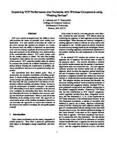
Fig. 3. Handling ACK at the TCP-ELN sender
ACK sequence number
TCP
TCP-ELN
Fig. 4. Transmission window size in the presence of packet loss
resolved with a simple and conservative assumption. A partial recovery acknowledgement is considered to be a sign of congestion. In case of a partial acknowledgement the congestion resolving mechanisms of the original TCP are invoked (Fast Retransmit - Fast Recovery). Otherwise, if a full recovery acknowledgement arrives (i.e. all segments sent before the retransmission are acknowledged by this packet) the sender resets the congestion window to the size it had when the packet was lost before fast retransmit and resumes normal operation (Figure 3, right hand side). Setting the congestion window to the value before detection of the loss (and not halving it as original TCP Reno would do) is justified by the fact that the packet loss has been detected as a loss due to packet corruption. The simple scenario of the new protocol’s behavior compared to the original one is illustrated in Figure 4. When packet 16 is lost on the wireless channel due to bit corruption the original TCP Reno protocol goes through the recovery phases [2]. After the recovery TCP Reno halves the congestion window and unnecessarily de-
488
Gergö Buchholcz et al.
creases the speed of data flow. On the contrary, TCP-ELN detects that the loss is due to packet corruption by examining the packet corruption counter, resends the lost packet, and waits for the recovery acknowledgement without halving the congestion window at fast retransmit. On receipt of the recovery ACK it resets the congestion window to the size before detecting the loss of packet 16 keeping the amount of packets in the network constant.
5 Simulation Results TCP Receivers
Base Station TCP Source Wired link, 1Mbit/s, 100 ms Wireless links 2 Mbit/s each
Fig. 5. Simulation topology
To measure the performance of TCP-ELN we have run a wide variety of simulations that are designed to cover realistic scenarios. The topology (Figure 5) consists of 5 nodes: a server, a base station (BS), and 3 mobile nodes. The server node connects to the BS with a 1 Mb/s link having a latency of 100ms, the BS offers a 2 Mb/s bandwidth connection to every mobile node in download and upload directions. Using this bandwidth distribution the topology offers the possibility of separating packet drops due to error and packet drops due to congestion. Congestion may occur only at the link from the server to the BS, packet loss due to bit error can occur only at the radio links. For traffic simulation FTP and web traffic is generated. The bulk FTP traffic is used to measure the steady state behavior of the protocol, while web traffic is used to examine the dynamic behavior. In the first group of simulations one FTP session is started at every mobile node. In the second group 5 web sessions are started at the mobile nodes. We measure the ftp throughput and the response time of web traffic. We use the SURGE model [8] to generate Web traffic which is based on real traffic traces and has been proved to generate realistic workloads. Uniform and Markov error models are two different approaches of modeling the lossy link behavior. Both of them are used to simulate packet loss at the link level. The mean value of the uniform distribution is varied between 0 and 0.2. Integrating channel fading and radio link parameters the Markov model takes the characteristics of wireless channels into account.
Explicit Loss Notification to Improve TCP Performance over Wireless Networks
489
Table 1. Parameters of the Markov model
Model number
User speed
Average error rate
Average error burst length
1 2 3
Pedestrian (1.5Km/h)
0.001 0.01 0.1
1.4913 4.0701 13.6708
4 5 6
intermediate
0.001 0.01 0.1
1.0083 1.0838 1.8629
0.001 0.01 0.1
1.0024 1.012 1.1317
7 8 9
High (100Km/h)
Using the Markov model we simulate radio links that a pedestrian and radio links that a high-speed user can experience with different packet drop probabilities (A more detailed description of Markov error model can be found in [9]). The different speed parameters with the same average error rates result in different expected values of burst error length as shown in Table 5.1. Note that due to the behavior of the physical channel the correlation of packet errors (the average burst length) is decreasing as the speed increases. Figure 6 shows the results of FTP traffic with uniform error model. The curves show that in error free transmission both protocols – the original and TCP-ELN – produce the same throughput. This is in accordance with the fact that TCP-ELN behaves exactly the same as the original protocol when there is no loss notification. In case of packet corruption TCP-ELN can achieve a 60-200% improvement in throughput for the examined error rates. The higher the error rates are the better the new protocol’s relative performance improvement is (see the right side of Figure 6). While the original protocol closes the congestion window as often as a packet is lost the TCP-ELN tries to avoid unnecessary window reductions. FTP throughput and the relative improvement with the Markov error model is shown in Figure 7. As it can be seen in on the right side of Figure 7 the relative improvement is between 110% and 140% for the high loss scenario (bulk 3,6,9). The improvement is between 60% and 120% for the medium loss scenario (bulk 2,5,8). Naturally, in the case of low loss ( bulk 1, 4, 7) the relative throughput increase is somewhat lower. Comparing the throughput and improvement values measured over uniform error with the ones produced over Markov error model, an interesting correlation can be recognized. Investigate the throughput values over an average error rate of 0.1 (10%). This error rate corresponds to the 3rd, 6th and 9th bulk in figure 6.3. Over the uniform model TCP-ELN produced a throughput of 8407 kBytes/s. The values for the Markov models 3, 6 and 9 are 18433, 9965, 8685 kBytes/s respectively. As the speed parameter of the Markov model increases the average length of an error burst decreases. Thus
Gergö Buchholcz et al.
50
250 Improvement (%)
Throughput (kB/s)
490
40 30 20 10 0
T CP-ELN T CP Reno 0
2
200 150 100
4 6 8 10 12 14 16 18 20 Packet error rate (%)
50 0 0
2 4 6 8 10 12 14 16 18 20 Packet error rate (%)
Fig. 6. The throughput and the relative improvement over FTP traffic with the uniform error model
Throughput (kBytes/s)
60 50
17%
68%
21%
40 30 20 10
25% 140%
136%
T CP Reno
122% 126%
113%
T CP-ELN % Improvement
0 1 (0.1) 2 (1) 3 (10) 4 (0.1) 5 (1) 6 (10) 7 (0.1) 8 (1) 9 (10) Markov error model (average packet error rate (%))
Fig. 7 The throughput and the relative improvement over FTP traffic with Markov error model
at higher speeds – as packet loss becomes sporadic – the Markov error model converges to the uniform error model. According to the results TCP-ELN is more effective when packet losses occur in bursts. Uniform, sporadic errors force the sender to reduce the size of congestion window more frequently than bursty errors with the same average error rate. In the third group of Markov models when the speed is the highest and the packet errors are barely correlated (distribution is close to uniform) the value of throughput is nearly the same as in the case of uniform distribution. In the web traffic simulation 5 sessions are used per mobile node. Each session simulates web page downloads with random object sizes, user think times, inter-object sizes and number of objects per page according to the SURGE model. The average response time of these downloads can be seen in the corresponding figures. In figure 8 the uniform error probability results are shown. Figure 9 shows the web results with the Markov error model. The average response times with the uniform error model are 10% to 60% better when using TCP-ELN. Figure 8 shows that at higher error rates the improvement becomes larger. In case of web traffic and the Markov error model (see figure 9) we observe slight improvements in case of low mean error rates (bulk 1,4,7), improvements between 15% and 30% in case of medium mean error rates, and 30% to 50% in case of high mean error rates.
14 12 10 8 6 4 2 0
T CP Reno T CP-ELN 0
2
4
Decrease (%)
Avg. resp. time (s)
Explicit Loss Notification to Improve TCP Performance over Wireless Networks
491
60 50 40 30 20 10 0
6 8 10 12 14 16 18 20 Packet error rate (%)
0
2
4 6 8 10 12 14 16 18 20 Packet error rate (%)
Avg. resp time (s)
Fig. 8. The average response time and relative improvement of web traffic with the uniform error model 7 6 5 4 3 2 1 0
49%
37%
33%
15% 1 (0.1)
17%
T CP Reno 9%
30%
21%
T CP-ELN
30%
2 (1) 3 (10) 4 (0.1) 5 (1) 6 (10) 7 (0.1) 8 (1) Markov error model (average packet error rate (%))
% Decrease 9 (10)
Fig. 9. The average response time and the relative improvement of web traffic with the Markov error model
6 Conclusions In this paper we have proposed a new technique to improve TCP’s low performance on wireless networks. The TCP-ELN protocol is based on the idea of the Explicit Loss Notification mechanism. TCP-ELN allows the TCP source to differentiate between packet losses due to wireless link error and packet losses due to congestion. Avoiding unnecessarily halving the congestion window when a packet is lost due to link error, the improved protocol guarantees higher performance than original TCP. We have explained the algorithm in detail and clarified the circumstances under which TCP-ELN can be used. TCP-ELN has applicability restrictions in terms of the network topology, the data flow direction, and the number of simultaneous flows at a mobile host in case the Header Checksum Option is not used. However, in spite of these practical limitations the new protocol is able to increase TCP performance in most common scenarios. Our simulation experiments have shown that TCP-ELN dramatically improves the performance of TCP over wireless links in a wide variety of environments. We have tested the protocol’s performance over random and bursty erroneous links with two different types of traffic, static FTP bulk load and dynamic web traffic. Results prove
492
Gergö Buchholcz et al.
that TCP-ELN produces a substantially better performance than the original TCP in all cases. In case of FTP traffic and high error probability throughput is improved between 110% and 200%. In case of Web traffic and high error probability mean response times are reduced between 30% and 60%.
References 1. W. Richard Stevens, TCP/IP Illustrated, Volume 1 2. TCP Slow Start, Congestion Avoidance, Fast Retransmit, and Fast Recovery Algorithms, Network Working Group, RFC 2001 3. The NewReno Modification to TCP's Fast Recovery Algorithm, RFC 2582 4. H. Balakrishnan, V. N. Padmanabhan, S. Seshan, and R. H. Katz, A Comparison of Mechanism for Improving TCP Performance over Wireless Links, IEEE/ACM Trans. on Networking, 5(6), December 1997. 5. TCP Selective Acknowledgment Options, RFC 2018 6. R. K. Balan et. al, TCP Hack: TCP Header Checksum Option to Improve Performance over Loosy Links, IEEE Infocom 2001 7. Hypertext Transfer Protocol - HTTP/1.1, RFC 2616 8. P. Barford and M. E. Crovella, "Generating Representative Web Workloads for Network and Server Performance Evaluation," in Proceedings of Performance '98/ACM SIGMETRICS '98, pp. 151-160, Madison WI. 9. Performance of TCP on Wireless Fading Links with Memory, A. Chockalingam, M. Zorzi, Ramesh R. Rao, ICC 1998 10. Andrea Zanella, Gregorio Procissi, Mario Gerla, M.Y. "Medy" Sanadidi : TCP Westwood: Analytic Model and Performance Evaluation, Globecom 2001