Vitaly Surazhsky and Craig Gotsman. Center for Graphics and Geometric Computing. Department of Computer Science. Technion—Israel Institute of Technology.
Eurographics Symposium on Geometry Processing (2003) L. Kobbelt, P. Schröder, H. Hoppe (Editors)
Explicit Surface Remeshing Vitaly Surazhsky and Craig Gotsman Center for Graphics and Geometric Computing Department of Computer Science Technion—Israel Institute of Technology
Abstract We present a new remeshing scheme based on the idea of improving mesh quality by a series of local modifications of the mesh geometry and connectivity. Our contribution to the family of local modification techniques is an areabased smoothing technique. Area-based smoothing allows the control of both triangle quality and vertex sampling over the mesh, as a function of some criteria, e.g. the mesh curvature. To perform local modifications of arbitrary genus meshes we use dynamic patch-wise parameterization. The parameterization is constructed and updated onthe-fly as the algorithm progresses with local updates. As a post-processing stage, we introduce a new algorithm to improve the regularity of the mesh connectivity. The algorithm is able to create an unstructured mesh with a very small number of irregular vertices. Our remeshing scheme is robust, runs at interactive speeds and can be applied to arbitrary complex meshes. Categories and Subject Descriptors (according to ACM CCS): I.3.5 [Computer Graphics]: Computational Geometry and Object Modeling
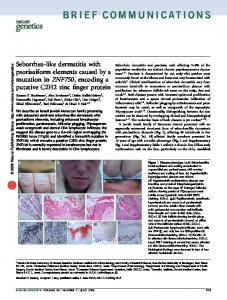
1. Introduction The ubiquity of 3D models used in applications ranging from Internet shopping and cinematography to heavy industry and scientific visualization cannot be denied. However, most existing 3D models can hardly be called satisfactory. The root of this problem lies mostly in the 3D model acquisition process. Whether this is done using interactive solid modeling software or semi-automatically using a scanning device, it remains a tedious and error-prone procedure. Despite the recent advances, e.g. [11, 17, 19], the process of simplifying scanned models with hundreds of millions of points is primarily concerned with preserving geometry and topology and does not emphasize sampling or the quality of triangles. Models generated by CAD software usually reflect the regular sampling of the underlying parametric domain instead of the model features. Therefore, the resulting models are usually not sampled properly, and may contain a large number of redundant vertices. As an attempt to fix this, CAD software may produce a large number of badly shaped long triangles to better approximate flat or developable regions. As a result, most existing meshes can be considerably improved in terms of their size, vertex sampling and triangle quality. The process that corrects the given mesh geometry and connectivity, while providing decent fidelity, is commonly known as remeshing, see Figure 1. Over the years, remeshing has become a fundamental component of the digital mesh processing field. Highly regular meshes, both in terms of their connectivity and geometry, are necessary for engineers performing numerical computations, such as finite element analysis. These c The Eurographics Association 2003. �
original (8,268 vertices)
remesh (9,240 vertices)
Figure 1: A remeshing example for the Venus model.
meshes are used, for instance, to calculate mechanical stress, solve heat and flow differential equations or simulate various processes. A high-quality mesh provides good conditioning of the system, and minimizes numerical errors and singularities that might otherwise arise. Hence, within the community of engineers the emphasis is on the quality of the mesh elements—mostly triangles or quads. The computer graphics and modeling community, on the other hand, is concerned with another aspect of remeshing. Their focus is on the tradeoff between the visual quality of the result, the speed of the remeshing operation, and the optimization of the number of polygons in order to achieve interactive rendering speeds.
Vitaly Surazhsky and Craig Gotsman / Explicit Surface Remeshing
1.1. Related Works Over the last decade, an abundance of remeshing algorithms have been proposed. One group of algorithms, e.g. [6,13,18], is based on partitioning 3D meshes into patches, and treating each patch separately, usually with subdivision techniques. While these techniques yield reasonable results, they are very sensitive to the patch structure, and the vertex sampling is difficult to control. More recent remeshing algorithms, e.g. [2, 12, 16] are based on global parameterization of the original mesh, and then a resampling of the parameter domain. Following this, the new triangulation is “projected” back into 3D space, resulting in an improved version of the original model. The main drawback of the global parameterization methods is the sensitivity of the result to the specific parameterization used, and to the cut used to force models that are not isomorphic to a disk to be so. Embedding a non-trivial 3D structure in the parameter plane severely distorts this structure, and important information, which is not specified explicitly, may be lost on the way. Even if the parameterization minimizes the metric distortion of the 3D original in some reasonable sense, it is impossible to eliminate it completely. Moreover, methods finding a global parameterization are slow, usually involving the solution of a large set of (sometimes nonlinear) equations. Recent progress may accelerate the process to almost linear time even for large meshes, using multi-resolutional approaches, e.g. [22], inspired by multi-grid methods together with good preconditioning. Unfortunately, when dealing with extremely large meshes, or meshes with severe isoperimetric distortion (like sock-shaped regions) numerical precision issues may arise. In such cases, a global parameterization is almost impossible to perform without using multi-scale or precise arithmetic representation of the parametric domain. The main alternative to global parameterization is to work directly on the surface and perform a series of local modifications on the mesh. This approach is also known as the mesh adaptation process and is the one we use in this work. Remeshing algorithms using this approach [9, 10, 14, 15, 21, 28] usually involve computationally expensive optimizations in 3D or more efficient but less accurate optimization in the tangent plane. Another difficulty of this approach is that the mesh vertices during the adaptation process must remain on the original mesh. In Section 3.2 we discuss this problem and present our solution. 1.2. Contribution and Overview In this paper we present a remeshing method which we call explicit. By explicit we mean that we operate directly on the mesh surface and apply local modifications to it, instead of working on some “indirect” representation of the surface, e.g. on a global parametric domain. The components of our remeshing algorithm are natural and straightforward ways to improve a mesh. Our scheme is close in spirit to those in [10, 14] performing a series of local modifications on the mesh. However, we use local parameterization to reduce the problem of local mesh optimizations to 2D.
Our remeshing algorithm incorporates a number of novel techniques, each of independent interest. The central technique is the area-based mesh optimization described in Section 3, which manipulates the areas of triangles in order to achieve a uniform or otherwise specified vertex sampling. A novel overlapping parameterization technique presented in Section 4 dynamically builds a local parameterization of the surface using a set of patches, which may overlap. This parameterization technique allows to apply 2D mesh optimization methods to 3D meshes in an efficient and precise manner. Section 5 presents a novel regularization technique that performs local modifications to the mesh connectivity, resulting in a mesh whose connectivity is extremely regular. When combined, our techniques provide an accurate and robust remeshing algorithm that can be applied to meshes of arbitrary genus. Our remeshing scheme is very efficient, allowing remeshing at interactive rates for meshes of up to tens of thousands of vertices. 2. Geometric Background The input of our remeshing scheme is a 2-manifold (except at boundaries) 3D mesh MO with arbitrary genus and possible holes. We consider MO to be a piecewise linear approximation of a smooth surface, which is C1 -continuous except at boundaries and a set of curves specified by feature edges. These feature edges can be provided by the user or computed automatically as edges whose dihedral angle is less than some threshold angle. More advanced feature detection techniques [31] may also be used. Surface reconstruction requires normal information at the mesh vertices. If the normals at the mesh vertices are not given, we use a method similar to [20,21] to define them. Every vertex is assigned a normal defined as the weighted average of the normals of the faces adjacent to it. The weights are proportional to the angles of the corresponding faces at the vertex and sum to unity. Normals of a vertex lying on feature edges are not the same within all its adjacent faces. They are also defined by the weighted average of the face normals but as if the mesh was cut along the feature edges at the vertex. 2.1. Surface Reconstruction We perform an estimate of the smooth surface in the vicinity of a mesh triangle. This may be obtained by reconstructing an approximation of the surface using triangular cubic Bézier patches for every face of MO . Vlachos et al. [29] presented a simple and efficient yet robust and accurate method to construct such curved patches called PN triangles. The triangle vertex normals together with vertex coordinates are used to construct a PN triangle. PN triangles usually maintain a G1 -continuous surface along adjacent triangles when their common vertices have identical normals. The normal of any point within a PN triangle is defined as an efficient quadratic interpolation of the normals at the triangle vertices. Walton and Meek [30] presented a more complex and computationally expensive method to create triangular patches c The Eurographics Association 2003. �
Vitaly Surazhsky and Craig Gotsman / Explicit Surface Remeshing
that guarantees G1 -continuity on the patch boundaries. Nevertheless, we use PN triangles as a good tradeoff between accuracy and efficiency. Given a point q inside a triangular face f = (q1 , q2 , q3 ), the corresponding point on the surface of the PN triangle of f as well as the normal at this point can be uniquely defined by the barycentric coordinates of q with respect to f . The barycentric coordinates are the triplet (b1 , b2 , b3 ) such that b1 , b2 , b3 are positive and satisfy: q = b1 q1 + b2 q2 + b3 q3 . (b1 , b2 , b3 ) are uniquely defined by:
Before remeshing M is initialized to MO . To ensure fidelity we apply a modification only if all faces created or affected by the modification satisfy the error conditions defined in Section 2.2. The main stages of our remeshing scheme are as follows: 1. Adjust the number of vertices of M; 2. Apply the area-based remeshing procedure on M; 3. Regularize M using the algorithm of Section 5; 4. Apply the angle-based smoothing procedure on M.
A(q, q2 , q3 ) 2 A(q, q3 , q1 ) 3 A(q, q1 , q2 ) ,b = ,b = , A(q1 , q2 , q3 ) A(q1 , q2 , q3 ) A(q1 , q2 , q3 )
Edge-collapse and edge-split are used to change the number of mesh vertices. Edge-flip and vertex relocation improve the quality of the mesh triangles. The area-based remeshing procedure is the heart of our remeshing scheme and produces a mesh with high quality triangles and the required vertex sampling. Another two stages improve the mesh quality further. The regularization stage improves the regularity of the mesh connectivity leaving only a small number of irregular vertices. The angle-based smoothing then polishes the mesh to obtain the optimal mesh geometry without changing its connectivity. We apply edge-flips if the minimal angle between all the angles of the triangles adjacent to the edge is increased. The area-based remeshing and the angle-based smoothing involve the most critical and difficult operation—vertex relocation.
b1 =
where A is the area of a triangle given its three vertices. Note that if A is the signed area (see (3) in Section 3.3.2), then barycentric coordinates with respect to f are well defined for any point in the plane but are not necessarily positive. 2.2. Controlling Fidelity To ensure fidelity of the new mesh to the geometry of the original mesh two error measures are used to evaluate the distance between the two meshes. Our measures are conceptually similar to those of Frey and Borouchaki [10] and are defined for a face instead of an edge. Let f = (v1 , v2 , v3 ) be a face whose error is to be estimated. The first measure Esmth captures the degree of smoothness and should not exceed some threshold angle θsmth : Esmth ( f ) =
max �N f , Nvi � < cos θsmth .
(1)
i∈{1,2,3}
N f and Nv are unit normals of f and its vertex v, respectively; �·, ·� denotes the dot product. Nv is taken from the original surface. Intuitively, Esmth describes how well f coincides with tangent planes of the surface at the vertices of f . The second measure Edist captures the gap between f and the surface: Edist ( f ) =
max �Nvi , Nvi+1 � < cos θdist .
(2)
i∈{1,2,3}
Vertex indices are modulo 3; θdist is a threshold angle. A greater value of the maximal angle between the normals of two face vertices corresponds to a more curved surface above face f , and thus, to a bigger distance. The beauty of these two measures is that they involve only normal directions. In addition to the computational efficiency, being used together these two measures are also robust and accurate. 3. Remeshing The focus of our remeshing scheme is on maximizing the angles of all triangles of the mesh. Remeshing of the given mesh MO is performed by a series of local modifications. The most well-known and commonly used local modifications are edge-flip, edge-collapse, edge-split and vertex relocation. Modifications are applied sequentially in order to achieve desirable mesh characteristics. We apply local modifications on the new mesh M, while the original mesh MO provides a reference to the geometry of the original mesh. c The Eurographics Association 2003. �
3.1. Vertex Relocation Let v be a vertex having location x(v) and whose neighbors are v1 , . . ., vk with locations x(v1 ), . . ., x(vk ), respectively, and k is the vertex degree. We want to find a new location xnew (v) satisfying some condition, e.g. improving the angles of the triangles incident on v. A solution to this problem that directly finds xnew (v) in 3D usually involves solving a difficult optimization problem, which may be non-convex and have non-linear constraints. We overcome this problem by mapping faces incident on v into the plane and solving the problem there. The location computed in the plane is then brought back to the original surface. Let S(v) be a sub-mesh of M containing only v, v1 , . . ., vk and faces incident on v. We map S(v) into the plane using a natural and simple method approximating the geodesic polar map [23], as described, for example, by Welch and Witkin [32] and Floater [7]. Let p, p1 , . . ., pk be the positions of vertices v, v1 , . . ., vk within the resulting mapping SP (v). p is mapped to the origin. p1 , . . ., pk satisfy the following conditions: the distances between p and its neighbors are the same as the corresponding distances in M, namely, �p − pi � = �x(v) − x(vi )� for 1 ≤ i ≤ k. The angles of all triangles at p are proportional to the corresponding angles in M and sum to 2π. The next step is to find a new location pnew of p. A method commonly used to move p in order to improve the angles of the adjacent faces is Laplacian smoothing. pnew is taken to be the average of p1 , . . ., pk . Being the most efficient method,
Vitaly Surazhsky and Craig Gotsman / Explicit Surface Remeshing
Laplacian smoothing has several serious drawbacks. The solution is a gross approximation, and may produce inverted (invalid) triangles. In our work, we use a method due to Surazhsky and Gotsman [25] called weighted angle-based smoothing. This method is simple and accurate and almost as efficient as Laplacian smoothing. 3.2. Back to the Original Surface After the new vertex location in the plane (pnew ) has been found, we need to find its corresponding location on the original surface, namely, to find xnew (v). Existing remeshing methods, e.g. [10, 15, 21] solve this problem by finding the vertex projection onto the original surface. Projecting the vertex involves a computationally expensive and not always accurate computation that without special care may even lead to topological errors during the remeshing process. In his pioneering work, Turk [28] introduced a technique to keep track between meshes on different level of details of the model to allow smooth transition between the levels. Unfortunately, this technique assumes that the meshes on different levels are static, each of them has already undergone the remeshing process. In our case, one of the meshes (M) is constantly changing by local modifications, and thus we need a dynamic tracking mechanism. First, we need to reference every vertex of M with its exact position on the original surface. If we could assume that M is always an oversampled version of MO , then the above references would be sufficient to efficiently locate xnew (v). However, in a typical remeshing scenario M is down-sampled. To be independent of the required sampling, parameterization techniques are used. In order to find xnew (v) precisely and efficiently, we use a novel patch-wise parameterization technique that we call overlapping parameterization. This technique aims to overcome both the problems of global parameterization (see Section 1.1) and the remeshing problems that usually arise near the patch boundaries when parameterizing based on mesh segmentation. Since our parameterization technique is patch-wise, similarly to techniques based on mesh segmentation, we are also able to deal with meshes of arbitrary genus and boundaries. The construction of the overlapping parameterization is described in Section 4. 3.2.1. The Algorithm For every vertex v� of M, we maintain its exact position on the original surface as a pair ( f , b), where f is a face of MO and b are barycentric coordinates. A point on the reconstructed surface is uniquely defined by b and the PN triangle corresponding to f ; see Section 2.1. Let f 2D be the face in the mapping SP (v) containing pnew , and bM = (b1M , b2M , b3M ) the barycentric coordinates of pnew with respect to f2D . Let u1 , u2 , u3 be the vertices of the triangle of M corresponding to f2D . The corresponding original surface positions of u1 , u2 , u3 are ( f1 , b1 ), ( f 2 , b2 ) and ( f3 , b3 ). Our goal is to find ( fnew , bnew ) corresponding to pnew . We solve this using a parameterization of a region of the original mesh MO containing f1 , f 2 and f3 . Let P be a
(a)
(b)
(c)
(d)
Figure 2: Vertex relocation. (a) The new position of the vertex in the 2D mapping. (b) The triangle containing the new position in M. (c) The colored vertices in (b) correspond to three faces of the original mesh MO . (d) A patch containing all these vertices is constructed and then parameterized. The position in the patch is computed using the corresponding barycentric coordinates of the 2D mapping. 2D mesh defining such a parameterization. The boundary of P is convex. See Figure 2. In Section 4 we show how to construct such a parameterization very efficiently. Next we find q1 , q2 , q3 (the locations of u1 , u2 , u3 in P), using barycentric coordinates b1 , b2 , b3 and the faces in P corresponding to f1 , f2 and f3 . We define q to be a point in a parametric domain P of MO corresponding to pnew : q = b1M q1 + b2M q2 + b3M q3 . The last step is to find a triangle in P containing q. This can be done using a method described by Owen et al. [20]. We start from an arbitrary face f � and analyze the barycentric coordinates b� of q with respect to f � . If all the components of b� are positive, then q lies in f � . Otherwise, we advance to the next face in the direction corresponding to a negative component of b� . The efficiency of this search depends on the starting face. Taking into account the fact that pnew is usually close to p, we start from the face of MO that contained v before relocation. If this face is not in P, we choose a face fi from { f1 , f2 , f3 } such that bi = max{b1M , b2M , b3M }, namely, the face closest to q. This reduces the average number of faces that we test during the search to about 1.2 faces, which is essentially constant time. 3.3. Controlling Sampling and Triangle Quality The idea of varying the mesh vertex density according to the curvature dates back to Turk [28]. The mesh adaptation remeshing techniques, e.g. [10, 21], typically use edgecollapse and edge-split operations to control the sampling rate. The disadvantage of this approach is that it is difficult to control the resulting number of vertices. Alliez et al. [2] use a half-toning technique to resample a discrete (pixel grid) representation of the parametric domain. The shortcoming of this extremely fast technique is that it can be applied only to meshes isomorphic to a disk, and is not suitable for models with significant isoperimetric distortion. In a subsequent work, Alliez et al. [1] use a weighted centroidal Voronoi tessellation to precisely sample very large meshes isotropically. However, since it is applied to the global parametric domain, the technique is still limited to meshes isomorphic to a disk. This work presents a novel technique for sampling 3D meshes. It is based on the area equalization technique introduced in [25]. We show how to apply this 2D remeshing technique to arbitrary complex 3D meshes and extend it to deal with a density function, e.g. the mesh curvature. c The Eurographics Association 2003. �
Vitaly Surazhsky and Craig Gotsman / Explicit Surface Remeshing
as follows: k � �2 (x, y) = arg min ∑ Ai (x, y) − µi A . (x,y) i=1
(a)
(b)
(c)
(d)
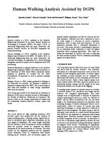
Figure 3: Area-based remeshing: (a) The original mesh. (b) The areas of triangles are equalized. (c) Discarding the edges reveals the uniform vertex sampling. (d) A series of alternations between Delaunay edge-flips and area equalization results in a close to regular mesh. 3.3.1. Area-based Remeshing The concept of triangle areas has never been used as a central factor in mesh generation. Triangle areas are usually used to assist, analyze or control meshing. The reason for this is that by using triangle areas alone we cannot obtain meshes of reasonable quality. A mesh optimization that equalizes the areas of the mesh triangles or brings triangle areas to specified (absolute or relative) values will, in most cases, result in many long and skinny triangles. Nevertheless, Surazhsky and Gotsman [25] discovered that a 2D triangulation having triangles with equal (or close to equal) areas has globally uniform spatial vertex sampling; see Figure 3(b, c). They presented the following remeshing scheme that exploits this: Alternate between area equalization and a series of angle-improving (Delaunay) edge-flips. Applying this simple scheme results in a 2D mesh with a very uniform sampling and well-shaped triangles. See Figure 3(d). It is important to mention that this alternation process does not usually converge. After a uniform sampling rate is obtained, the process begins to oscillate, producing different but similar uniform vertex distributions. However, this oscillation is not a problem for our remeshing algorithm, since subsequent steps of our remeshing algorithm improve quality of the mesh further by regularizing and smoothing it. 3.3.2. Area-based Vertex Relocation Area equalization is done iteratively by relocating every vertex such that the areas of the triangles incident on the vertex are as equal as possible. In this work we extend this method to relocating vertices such that the ratios between the areas are as close as possible to some specified values. To define this formally, we return to the definitions of point p and its neighbors p1 , . . ., pk from Section 3.1. Let (xi , yi ) be the coordinates of pi . Our goal is to find p = (x, y) such that the ratios of the triangle areas are as close as possible to µ1 , . . ., µk . All µi ’s are positive and sum to unity. Denote by Ai (x, y) the area of triangle p, pi , pi+1 : � � � xi yi 1�� � 1 Ai (x, y) = ��xi+1 yi+1 1�� . (3) 2� x y 1� Let A be the area of polygon (p1 , . . ., pk ), which may be computed as ∑ki=1 Ai (0, 0). Now the location of p is defined c The Eurographics Association 2003. �
(4)
This reduces to solving a system of two linear equations in x and y, which has a unique solution. Thus, area-based relocation is almost as efficient as Laplacian smoothing. 3.3.3. Curvature Sensitive Remeshing We now show how to use area-based vertex relocation to produce a mesh reflecting the curvature of the original mesh. Intuitively, more curved regions of M will contain small triangles and a dense vertex sampling, while almost flat regions will have large triangles with more sparse vertices. The idea is to specify ratios between triangle areas depending on curvature. Let Ψ be a density function defined over MO . For every vertex v of MO that does not lie on the boundary of MO or on a feature edge, we define Ψ(v) as 1/(α|K(v)| + βH2 (v)), where H(v) and K(v) are approximated discrete Gaussian and mean curvatures, respectively. α and β are user-defined values, which are positive and sum to unity. Usually we use α = β = 0.5. We compute H(v) and K(v) using the method described in [5], where the Gauss-Bonnet (also known as angle deficit) method is used for K(v). This method is the best tradeoff between efficiency, accuracy and robustness. For a comparison of existing techniques to approximate discrete curvature, see the survey of Surazhsky et al. [24]. For a vertex v lying on the boundary, Ψ(v) is defined as the average of Ψ at the neighbors of v, ignoring other vertices on the boundary. For vertices that lie on the feature edges the average is taken in a manner similar to defining normals for these vertices (see Section 2). Since Ψ is defined using discrete curvature approximation its values may vary considerably. Ψ is also very sensitive to noise in either the geometry or connectivity of MO . To alleviate this, we truncate all extreme values of Ψ. However, the values of Ψ at adjacent vertices may still be too different to prescribe the density of vertex sampling. We apply a signal processing approach similarly to [2]. In signal processing terms, Ψ contains high frequencies. To remove them, we apply Laplacian smoothing on Ψ as the simplest possible approximation of a low-pass filter. A user-defined parameter ksmooth , roughly describing the threshold of the low-pass filter, is the number of times we apply a single iteration of Laplacian smoothing. Also it is useful to allow the user to control the contrast of Ψ. Our contrast function is defined as a simple gamma function g(ψ, γ) = ψγ . Now after we have defined Ψ for all vertices of MO , we define Ψ for any point located on a face f of MO to be the linear interpolation of Ψ at the vertices of f . The last step is to define the triangle area ratios that we use in vertex relocation. We return to the notations of Sections 3.1 and 3.3.2. Define µ�i for 1 ≤ i ≤ k as the average between Ψ(vi ) and Ψ(vi+1 ). The value µ�i describes the required density of the corresponding triangle (v, vi , vi+1 ).
Vitaly Surazhsky and Craig Gotsman / Explicit Surface Remeshing
Note that vertices v, vi , vi+1 are of M, and to obtain Ψ for the corresponding positions on the original surface, we use the original vertices together with the corresponding barycentric coordinates that are stored in v, vi , vi+1 (defined in Section 3.2). µ�1 , . . ., µ�k are then normalized to obtain valid µ1 , . . ., µk , namely µi = µ�i / ∑kj=1 µ�j . 3.4. Implementation Notes Area-based remeshing: The procedure is controlled by two parameters: nstep and narea . We alternate nstep times between curvature sensitive area equalization and a series of Delaunay edge-flips. Area equalization consists of narea iterations of applying area-based vertex relocation for every vertex of M. Edge-flips are performed until a Delaunay edge-flip can no longer be applied. nstep and narea are usually small. There is no need to bring the triangle areas as close as possible to some required ratios to change vertex sampling. A very small number (1 to 3) of narea iterations is enough to move vertices in the proper direction towards the required vertex sampling. nstep is usually between 5 and 10 and is sufficient to produce a mesh with vertex sampling very close to the required one. Angle-based smoothing: The parameter mstep of this procedure defines how many iterations of weighted angle-based smoothing are performed. Each iteration relocates once every vertex of M. mstep is also small and usually somewhere between 5 and 10. Adjusting the number of the mesh vertices: To obtain a mesh with the number of vertices specified by the user, we apply local refinement or simplification operations to the mesh. Until the required number of vertices is achieved we perform a series of edge-collapse or edge-split modifications (depending on the required size) such that the edges affected by the modifications are an independent edge set. Edges whose faces have minimal/maximal error metrics are simplified/refined first. Before every series of modifications we apply the area-based remeshing procedure with nstep = 1 to maintain a fair vertex sampling. Small handles and other problematic regions: When we apply local modifications on the mesh, we check that the modifications do not result in violation of the fidelity criteria of Section 2.2. However, some regions of the initial mesh may violate them. To alleviate this we refine these regions prior to the area-based remeshing. For example, see Figure 8, where the “nose” part of the helmet model was refined prior to the main remeshing algorithm. Some regions of the mesh may initially have regions with a very large “error” according to our error measures. We do not remesh such regions and consider them as “special features”. Refining these regions may result in the addition of a very large number of vertices. Since the error measures will prevent applying any local modification in these regions anyway, we do not need to handle these regions explicitly. For example, see Figure 7(e) for the remeshed triceratops model, where the very tips of the horns have a small number of vertices that were not affected by remeshing.
4. Overlapping Parameterization In contrast to previous works that are based on mesh segmentation to build an atlas of disjoint patches isomorphic to a disk, our parameterization scheme uses patches that overlap each other. Since we use mesh parameterization for local operations on the mesh, we do not need to minimize the number of patches. Building overlapping patches, the patch boundaries can be chosen independently for every patch. The freedom to choose the shape and the size of the patches can considerably reduce the error (distortion) caused by mapping a 3D mesh with an arbitrary genus and holes to the 2D parametric domain. Moreover, using overlapping patches we avoid difficulties that usually arise near the patch boundaries when parameterizing based on mesh segmentation. Another advantage of the overlapping parameterization is that the small size of every patch allows us to construct its parameterization very quickly. Thus, the total computational cost is even smaller than that of a global parameterization. The overlapping parameterization is constructed dynamically when a specific region of the original mesh is to be parameterized to perform a local operation on the mesh. For this region we create a patch containing it and parameterize the patch. For our set of local operations on the mesh, we need only construct a patch of the mesh containing three faces. Before creating a new patch that includes the three required faces, we first check if such a patch already exists. We show how to find such a patch very efficiently in Section 4.3. 4.1. Patch Construction Given three arbitrary faces f1 , f 2 and f3 of the original mesh, we must find a patch of the mesh that is isomorphic to a disk and contains the faces. Intuitively, for every face fi we find a circular neighborhood Ni of minimal radius that contains the other two faces. The patch is taken to be the union of N1 , N2 and N3 . Taking the union of the neighborhoods as a patch for f1 , f 2 and f3 , results in a patch that is small enough to have small distortion yet large enough to be reused for another triplet of faces. To construct the union of N1 , N2 and N3 we do the following: Begin with an empty patch. From each face fi , i ∈ {1, 2, 3}, initiate a breadth-first search over the faces of the mesh. All faces visited during the search are added to the patch. Check that adding a new face preserves the patch topology, which should be isomorphic to a disk. The search terminates when the other two faces fi+1 and fi+2 are visited. Face indices are modulo 3. As a post-processing step of the patch construction, we smooth the boundary of the patch by trimming all triangles which have all three vertices on the patch boundary. Such triangles are usually called ears. We remove all faces that are ears, ignoring the input faces f1 , f 2 , f 3 . This results in a more "circular" boundary and in less distortion of the patch parameterization. 4.2. Patch Flattening After the patch is constructed, we embed it into the plane. The boundary of the patch is embedded as a convex polygon, c The Eurographics Association 2003. �
Vitaly Surazhsky and Craig Gotsman / Explicit Surface Remeshing
whose vertices lie on the unit circle. The distances between the vertices on the circle are proportional to those of the 3D patch. Numerous works over the last decade have presented different techniques to embed a mesh inside a polygon with a fixed boundary, e.g. [6, 7]. The technique of choice is the conformal mapping [6]. This technique minimizes local angle deformation of the 3D mesh, and thus, better preserves its geometric properties. Unfortunately, this technique has one serious drawback. It cannot guarantee that the embedded mesh is free from foldovers. The only techniques that can analytically guarantee foldover-free embedding are the shape-preserving [7] and mean-value coordinates [8] techniques developed by Floater. We use the latter since it is more efficient, produces a parameterization with properties close to the conformal mapping yet is always valid.
4.3. Finding an Existing Patch Our overlapping parameterization scheme maintains a pool of patches. Before creating a new patch that parameterizes a mesh region containing faces f1 , f 2 and f3 , we first try to find such a patch in the pool of existing patches. We do this very efficiently using the following simple data structure. For every face f in the original mesh we maintain a list L( f ) of pairs (p, f p ), where p is a patch that parameterizes a region of the original mesh containing f , and fp is the face corresponding to f within p. The implementation of the list actually contains pairs of pointers. When a patch is created, all faces of the original mesh corresponding to that patch are updated, and a new pair is added to the front of L for these faces. Now given f1 , f 2 and f3 , our goal is to find a patch containing all the faces, or report that there is no such patch. The following search is performed: For each pair (p1 , ·) in L( f 1 ), we search for pair (p2 , ·) in L( f 2 ) such that p2 = p1 . If we succeed, we search for pair (p3 , ·) in L( f 3 ) such that p3 = p1 . If the last search is successful, p1 is a patch containing f1 , f2 and f3 . In any other case, failure is reported. The search performs at most |L( f1 )| · (|L( f 2 )| + |L( f 3 )|) comparisons, where |L| is the length of L. Thus, the time complexity of the search is O(k2 ), where k is the maximal length of the lists. Note that statistically the average length of L for all faces of the original mesh is about 3.5 for all meshes, with a maximal length of 5. Thus, the time complexity of O(k2 ) is actually O(1) in practice. However, this efficiency can be improved even further due to the space coherence of the local mesh operations. If the search was successful we move pairs containing the resulting patch to the front of the lists. Thus, in most cases the first element of lists L( f 1 ), L( f 2 ) and L( f3 ) will refer to a patch that will be found. Hence, in most cases we will find a patch by only two pointer comparisons. The mesh space coherence can be improved dramatically using a locality preserving vertex sequence, as described by Bogomjakov and Gotsman [3]. c The Eurographics Association 2003. �
4.4. Removing Unused Patches As long as our remeshing algorithm performs local operations, some patches may become unused. For example, if a low curvature region of the mesh has a dense vertex sampling in the original mesh, after the curvature sensitive areabased remeshing the vertices of this region will be more sparse. Hence, patches created by early operations may become too small to be used for later operations performed on larger triangles. By removing such unused patches we guarantee that memory consumed by the overlapping parameterization is bounded. To preserve efficiency we use a simple and efficient technique to remove unused patches. We associate a timer with every patch. If a patch was not used for a predefined period of time (a signal event), the patch is removed. The timer of a patch is reset every time the patch is accessed. A single clock tick corresponds to accessing any single patch in the pool. The initial timer value, namely, the time that a patch is kept unused in the pool, is a small constant factor (0.1– 0.3) obtained experimentally, times the number of faces in the resulting mesh. This technique is based on simulating multiple timers with a single clock in operating systems. We use a queue (list) of timers ordered by the time at which they are to signal. To prevent updating all elements of the queue, the deltas (differences) between the times of signals are used [26]. 5. Connectivity Regularization Another component of our remeshing scheme is an effective yet simple and efficient algorithm to improve the mesh quality by regularizing its connectivity. The algorithm performs a series of local operations that modify the mesh connectivity, namely, edge-flips, edge-collapses and edge-splits. Formally, improving regularity means minimizing the following function: �2 � (5) R(M) = ∑ d(v) − dopt (v) , v∈M
where d(v) is the degree (or valence) of vertex v and dopt (v) its optimal degree. Vertices on the boundary have dopt = 4, and for the rest of the vertices dopt = 6. We do not define this formally, but during the mesh regularization we allow only a small change in the total number of mesh vertices and vertex sampling along the mesh. We call an edge-flip basic if it decreases R(M). In their elegant work, Alliez et al. [2] proposed to randomly apply basic edge-flips to regularize mesh connectivity. This straightforward method results in some improvement. However, it still leaves too many irregular vertices even when basic edge-flips can no longer be applied; see Figure 5(b). The reason for this is that R has many local minima with respect to basic edge-flips. The intriguing question is how to continue from such a local minimum. It is theoretically possible to apply stochastic methods similar to simulated annealing that will allow R to escape from local minima and obtain the global minimum or at
Vitaly Surazhsky and Craig Gotsman / Explicit Surface Remeshing
(a)
(b)
(c)
(d)
(e)
Figure 4: Types of edges: (a) A long edge. (b) A short edge. (c) A drifting edge. (d) The drifting edge moved two steps to the right. (e) After angle-based smoothing. least a very good local minimum. However, our experiments have shown that the distance between local minima is large, hence, simulated annealing will converge very slowly to a good solution. During a large number of connectivity targeting modifications we can easily lose the curvature sensitive vertex sampling. Fortunately, we discovered a simple and intuitive method that minimizes R(M), applying modifications in a smart manner. We pose this problem as a puzzle. The player can click an edge to flip, collapse or split it. We call an edge easy if we can apply a basic edge-flip on it. The game starts with a mesh without easy edges, namely, when R(M) is at a local minimum. The goal of the game is to minimize R(M) further with a small number of mesh modifications. To visualize, we color vertices according to their degree. A vertex v is black if d(v) < dopt (v) and white when d(v) > dopt (v). The vertex is not colored when d(v) = dopt (v), namely, the player has solved the puzzle for v. See Figure 5(a). When solving the puzzle we discovered that there are three types of edges that are actually interesting, and for every type there is only one specific local modification to apply. Long edges: An edge is a long edge if both its vertices are white. The definition of a long edge is based on the connectivity alone. However, optimizing the mesh geometry using the angle-based smoothing reveals that long edges are actually geometrically longer than their nearby edges. Thus, the natural modification for this edge is to refine it. See Figure 4(a). Short edges: An edge is a short edge if both of its vertices are black. Short edges are actually shorter than other nearby edges if the mesh has been optimized using the anglebased smoothing procedure. Thus, we collapse short edges. See Figure 4(b). Drifting edges: An edge is a drifting edge if one of its endpoints is a white vertex and the other is black. Every drifting edge e has the following nice property: If we flip an edge e� incident on the white vertex that belongs to one of the faces adjacent to e, then e ‘disappears’ (loses its drifting property) and reappears as the opposite to e within the quad defined by e� . Thus, we say that we have moved a drifting edge. This allows us to move a pair of white and black vertices of a drifting edge across a regular region of the mesh; see Figure 4(c–e). If a drifting edge does not lie on the boundary, we can move it in two opposite directions. Note that when we move a drifting edge and all its neighboring vertices are regular, R(M) does not change. Also, we do not change R(M) when we split a long edge or col-
Figure 5: Regularizing the mesh. Black vertices have valence < 6 and white vertices > 6. Top: The mesh after applying area-based remeshing. Middle: All possible easy edgeflips have been performed. Bottom: Our regularization algorithm results in a mesh with a small number of irregular (colored) vertices.
lapse a short edge and then perform all possible basic edgeflips. 5.1. Solving the Puzzle To every edge among long, short or drifting edges, we apply only its corresponding operation. The central idea in solving the puzzle is to cause a drifting edge to migrate until it meets irregular vertices, and thus, an easy, long or short edge may appear. We perform operations on these edges, until only drifting edges are left. Then we choose an arbitrary drifting edge as the next edge to move. We proceed this way, until no drifting edge is left. This condition means that there are no easy, long and short edges as well, and the algorithm terminates. Consequently, the algorithm results in a mesh that has all irregular vertices surrounded by regular vertices. The number of such isolated irregular vertices is usually very small. See Figure 5(c). c The Eurographics Association 2003. �
Vitaly Surazhsky and Craig Gotsman / Explicit Surface Remeshing
5.2. Implementation Notes We do not perform any sort of global analysis of the mesh, but only local modifications corresponding to the edge type. Thus, the implementation of our algorithm is very simple. All easy, long, short and drifting edges are stored in a priority queue. Easy edges have the highest priority, drifting edges have the lowest priority. The priorities of long and short edges are equal, but may be different to favor edgesplit or edge-collapse in some rare cases. The algorithm processes the first edge in the queue until the queue empties. After each modification the queue is updated. The regularization algorithm we described so far considered only the connectivity of the mesh. Applying it to 3D meshes, we perform only the operations that satisfy the error condition defined in Section 2.2. Also, after each operation we apply a single iteration of angle-based smoothing on the region of the mesh affected by the modification. Otherwise, the error condition will sometimes prevent performing operations. 5.3. Possible Improvements It is possible to move an isolated irregular vertex v. This can be done by flipping an edge incident on v such that v will become regular. By doing so we move a black/white vertex and produce a new drifting edge that can be moved away from v. This operation completes the set of operations necessary to obtain the connectivity of some regular or almost regular mesh from the given mesh. Future work will include global analysis of the mesh in order to produce a mesh that has a semi-regular structure, namely, with subdivision connectivity. 6. Experimental Results We have implemented the algorithms described here in an interactive software system. The user is able to remesh models at interactive rates, and control the results using a small number of parameters. The most significant parameters are the number of vertices (or faces) in the result, and the contrast. The contrast determines how the local vertex density is affected by the surface curvature. The traditional way of measuring the quality of a remeshed model is by measuring the geometric properties of the resulting triangles and the combinatorial properties of the mesh. The two are obviously related. For the geometry, statistics are usually collected on the minimal angle of the triangles. Obviously this value is anywhere between 0◦ and 60◦ . For a high-quality mesh, the minimum of these values should be no less than 10◦ , and the average should be no less than 45◦ . For the connectivity, the distribution of vertex valences is an important factor. Of great interest are the number of irregular vertices, which is also a key for successful mesh compression. Table 1 shows the statistics of the remeshes of some popular 3D models. The examples on the first page are of the Venus model. Figure 6 shows remeshes of the cow model with different values of the contrast parameter. Figure 7 shows some other commonly available models. Figure 7(e) c The Eurographics Association 2003. �
Vertices
Irreg (%)
Min∠ (deg)
Ave∠ Error Time (deg) (10-3 ) (sec)
TG (kB)
Conn (bpv)
Geom (bpv)
Venus (original) 8,268 Venus (uniform) 9,240 Venus (non-uniform) 8,705
74.9 4.4 6.7
0.25◦ 25.8◦ 25.9◦
34.7◦ 53.3◦ 52.4◦
— 3.5 2.7
— 15.4 16.5
23.9 15.3 17.4
2.83 0.47 0.72
20.9 13.1 14.8
Cow Cow Cow Cow
2,904 4,551 4,984 5,249
38.1 9.5 10.2 10.3
2.8◦ 8.1◦ 12.5◦ 11.1◦
30.1◦ 48.8◦ 49.6◦ 49.2◦
— 5.8 5.0 4.8
— 8.2 8.9 9.3
7.89 8.95 9.67 11.3
1.89 0.93 0.95 0.94
20.4 15.2 14.9 14.0
Feline (original) Feline
49,864 10,825
63.8 13.8
3.8◦ 7.4◦
40.0◦ 48.3◦
— 6.4
— 74
100 21.3
2.38 1.09
14.2 15.1
Horse (original) Horse
19,851 5,695
64.5 10.3
1.7◦ 9.1◦
35.9◦ 50.1◦
— 6.1
— 28.4
46.0 11.0
2.34 0.97
16.6 14.8
Triceratops (original) 2,832 Triceratops 2,758
59.3 13.3
0.02◦ 5.6◦
29.6◦ 42.2◦
— 8.4
— 12.3
7.68 5.93
2.17 1.2
20.0 16.4
Fan disk (original) Fan disk
5,051 5,135
20.6 8.43
16.8◦ 16.8◦
43.0◦ 49.1◦
— 0.4
— 17.3
9.12 9.03
1.03 0.58
13.7 13.8
Helmet (original) Helmet
496 2,728
63.9 6.08
2.33◦ 14.8◦
34.5◦ 47.8◦
— 8.9
— 17.7
2.12 5.46
2.94 0.67
32.1 15.7
Model
(original) (a) (b) (c)
Table 1: Statistics on the remeshed models: number of ver-
tices, percentage of irregular vertices, minimal angle, average angle, error measured by Metro normalized to the bounding box diagonal, remeshing time, file size compressed by the Touma-Gotsman algorithm, connectivity and geometry compression in bits per vertex. demonstrates remeshing of the fan-disk model, in which the creases, corners and the shape of the boundary are preserved. All example have very good aspect ratios, and only a few lack in respect to the minimal angle. On a Pentium 4 PC (2.4 GHz) with 512 RAM, the remeshing operations run at interactive rates for most of the models. Another important factor in remeshing is fidelity to the original mesh. Table 1 presents the remeshing errors. The error is the Hausdorff distance normalized by the bounding box diagonal, obtained using the Metro tool [4]. These errors show a relatively high fidelity with respect to the number of the mesh vertices together with the main goal of our remeshing scheme for the triangle quality. The models were compressed using the commonly available Touma-Gotsman algorithm [27] with 12 bit for geometry quantization (per coordinate). The improvement in connectivity compression is obvious—almost all remeshes consume less than one bit per vertex for connectivity. Compression of geometry is also superior to the original models. 7. Conclusion This paper has introduced a systematic remeshing scheme whose main advantage over the existing ones is its robustness and speed, without sacrificing any quality in the results. In fact, in many cases, the results are even superior to others, mostly due to a novel mesh regularization algorithm. The reason the remesher is so fast and robust is that it is built on a series of highly efficient local operations. Hence, we manage to avoid the pitfalls of previous techniques: those that are mostly based on global operations, such as parameterization of the entire model, and those that perform computationally expensive 3D optimizations. Despite the operations being local, we are able to avoid error accumulation by
Vitaly Surazhsky and Craig Gotsman / Explicit Surface Remeshing
(a)
(b)
(c)
Figure 6: The cow model with different curvature contrasts.
(a)
(b)
(d)
(e)
(c)
(f)
Figure 7: (a) The horse model. (b) The feline model. (c) Zoom in on the “tail” part. (d) The curvature adapted remesh of the venus model. See also Figure 1. (e) The triceratops model. (f) The fandisk model with sharp features. comparing to a smooth approximation of the original geometry throughout the entire process. A number of the components of our remeshing scheme are of independent interest to the meshing community. The most significant one, in our opinion, is the connectivity regularizing technique. This is able to transform the connectivity into a very regular mesh, with very few isolated irregular vertices, while not changing significantly the total number of vertices during the process. Our technique to locally parameterize the mesh in a operation-sensitive manner allows us to take advantage of a variety of existing 2D meshing algorithms. Future work will include generalization of our techniques to quad-based meshes. Open questions: The drawback of the area-based remesh-
ing technique is its inability to control vertex sampling beyond the boundaries defined by feature edges. One possible solution is to relax error conditions on the feature edges and then to restore them in a post-processing stage using an approaches similar to [15]. Acknowledgments Thanks to Alla Sheffer for helpful discussions on remeshing, to Vladislav Kraevoy for helpful discussions on overlapping parameterization and its implementation, to Pierre Alliez for significantly improving our submitted version, and to the anonymous reviewers for their helpful comments. This research was partially funded by European grant HPRN-CT1999-00117 (MINGLE), German-Israel Fund grant I-62745.6 and Israel Ministry of Science grant 01-01-01509. c The Eurographics Association 2003. �
Vitaly Surazhsky and Craig Gotsman / Explicit Surface Remeshing
(a)
(b)
(c)
Figure 8: The helmet model. (a) The original model. (b) The remesh. (c) Zoom in on the “nose” part. References 1.
2.
3.
4.
5.
6.
7.
8. 9. 10.
11.
12.
13.
14. 15.
16.
P. Alliez, E. Colin de Verdière, O. Devillers, and M. Isenburg. Isotropic surface remeshing. To appear in Proceedings of Int. Conference on Shape Modeling and Applications, 2003. P. Alliez, M. Meyer, and M. Desbrun. Interactive geometry remeshing. ACM Transactions on Graphics. Special issue for SIGGRAPH conference, 21(3):347–354, 2002. A. Bogomjakov and C. Gotsman. Universal rendering sequences for transparent vertex caching of progressive meshes. Computer Graphics Forum, 20(2):137–148, 2002. P. Cignoni, C. Rocchini, and R. Scopigno. Metro: Measuring error on simplified surfaces. Computer Graphics Forum, 17(2):167–174, 1998. N. Dyn, K. Hormann, S.-J. Kim, and D. Levin. Optimizing 3D Triangulations Using Discrete Curvature Analysis. Innovations in Applied Mathematics. Vanderbilt University Press, Nashville, 2001. M. Eck, T. DeRose, T. Duchamp, H. Hoppe, M. Lounsbery, and W. Stuetzle. Multiresolution analysis of arbitrary meshes. Computer Graphics. SIGGRAPH ’95 Proceedings, 29:173– 182, 1995. M. S. Floater. Parameterization and smooth approximation of surface triangulation. Computer Aided Geometric Design, 14:231–250, 1997. M. S. Floater. Mean value coordinates. Computer Aided Geometric Design, 20:19–27, 2003. P. J. Frey. About surface remeshing. Proceedings of 9th International Meshing Roundtable, pages 123–136, 2000. P. J. Frey and H. Borouchaki. Geometric surface mesh optimization. Computing and Visualization in Science, 1:113–121, 1998. M. Garland and P. S. Heckbert. Surface simplification using quadric error metrics. Computer Graphics, 31(Proceedings of SIGGRAPH ’97):209–216, 1997. X. Gu, S. J. Gortler, and H. Hoppe. Geometry images. ACM Transactions on Graphics. Special issue for SIGGRAPH conference, 21(3):355–361, 2002. I. Guskov, K. Vidimce, W. Sweldens, and P. Schröder. Normal meshes. Computer Graphics. SIGGRAPH ’2000 Proceedings, pages 95–102, 2000. H. Hoppe. Progressive meshes. Computer Graphics. SIGGRAPH ’96 Proceedings, 30:99–108, 1996. H. Hoppe, T. DeRose, T. Duchamp, J. McDonald, and W. Stuetzle. Mesh optimization. Computer Graphics. SIGGRAPH ’93 Proceedings, 27:19–26, 1993. K. Hormann, U. Labsik, and G. Greiner. Remeshing triangulated surfaces with optimal parameterizations. ComputerAided Design, 33(11):779–788, September 2001.
c The Eurographics Association 2003. �
17. L. Kobbelt, S. Campagna, and H.-P. Seidel. A general framework for mesh decimation. Graphics Interface, pages 43–50, 1998. 18. A. W. F. Lee, W. Sweldens, P. Schröder, L. Cowsar, and D. Dobkin. MAPS: Multiresolution adaptive parameterization of surfaces. Computer Graphics. SIGGRAPH ’98 Proceedings, 32:95–104, 1998. 19. P. Lindstrom. Out-of-core simplification of large polygonal models. Computer Graphics. SIGGRAPH ’2000 Proceedings, pages 259–262, 2000. 20. S. J. Owen, D. R. White, and T. J. Tautges. Facet-based surfaces for 3D mesh generation. Proceedings of 11th International Meshing Roundtable, pages 297–312, 2002. 21. A. Rassineux, P. Villon, J.-M. Savignat, and O. Stab. Surface remeshing by local Hermite diffuse interpolation. International Journal for Numerical Methods in Engineering, 49:31– 49, 2000. 22. P. Sander, S. Gortler, J. Snyder, and H. Hoppe. Signalspecialized parametrization. Eurographics Workshop on Rendering, 2002. 23. D. J. Struik. Lectures on Classical Differential Geometry. Dover Publications, Inc., 1988. 24. T. Surazhsky, E. Magid, O. Soldea, G. Elber, and E. Rivlin. Computing Gaussian and mean curvatures on the triangular meshes. IEEE International Conference on Robotics & Automation, 2003. 25. V. Surazhsky and C. Gotsman. High quality compatible triangulations. Proceedings of 11th International Meshing Roundtable, pages 183–192, Sept. 2002. 26. A. S. Tanenbaum. Operating Systems: Design and Implementation. Prentice-Hall, Inc., 1987. 27. C. Touma and C. Gotsman. Triangle mesh compression. In Proceedings of Graphics Interface, Vancouver, 1998. 28. G. Turk. Re-tiling polygonal surfaces. Computer Graphics. SIGGRAPH ’92 Proceedings, 26:55–64, 1992. 29. A. Vlachos, J. Peters, C. Boyd, and J. L. Mitchell. Curved PN triangles. In Symposium on Interactive 3D Graphics, pages 159–166, 2001. 30. D. Walton and D. Meek. A triangular G1 patch from boundary curves. Computer Aided Design, 28(2):113–123, 1996. 31. K. Watanabe and A. Belyaev. Detection of salient curvature features on polygonal surfaces. Computer Graphics Forum, 20(3):385–392, 2001. 32. W. Welch and A. Witkin. Free form shape design using triangulated surfaces. In Computer Graphics (Proc. SIGGRAPH ’94), volume 28, 1994.