Exploiting Idle Communication Power to Improve Wireless Network Performance and Energy Efficiency Lei Guo1, Xiaoning Ding1 , Haining Wang2, Qun Li2 , Songqing Chen3, Xiaodong Zhang1 1 Ohio
State University Columbus, OH 43210, USA {lguo,dingxn,zhang}@cse.ohio-state.edu
2 College
of William and Mary Williamsburg, VA 23187, USA {hnw,liqun}@cs.wm.edu
Abstract— As a family of wireless local area network (WLAN) protocols between physical layer and higher-layer protocols, IEEE 802.11 has to accommodate the features and requirements of both ends. However, current practice has addressed the problems separately and is far from being satisfactory. On the one end, due to varying channel conditions, WLANs have to provide multiple data channel rates to support various bit error rates. A low channel rate station not only suffers low throughput itself, but also significantly degrades the throughput of other stations. On the other end, TCP is not energy efficient running on 802.11. This is because a wireless network interface (WNI) has to stay awake to generate timely acknowledgments during a TCP session, and hence, the energy consumed during idle awake time is wasted for channel listening. In this paper, considering the needs of both ends, we utilize the idle communication power of the WNI to improve the throughput and energy efficiency of stations in WLANs supporting multiple channel rates. We characterize the energy efficiency as energy per bit, instead of energy per second. Based on modeling and analysis, we propose a data forwarding mechanism and an energy-aware channel allocation mechanism. In such a system, a high channel rate station relays data frames between its neighboring stations with low channel rates and Access Point, improving their throughput and energy efficiency. Different from traditional relaying approaches, our scheme compensates for the energy consumption for data forwarding. The forwarding station gets additional channel access time from its beneficiaries, leading to the increase of its own throughput without compromising its energy efficiency. We implement a prototype of our proposed system and evaluate it through extensive experiments. Our results show significant performance improvements for both low and high channel rate stations.
I. I NTRODUCTION Mobile devices are usually driven by battery power. Due to limited battery capacity, it is essential to reduce power consumption of mobile devices without degrading their performance. In mobile communications, wireless network interfaces (WNIs) consume a significant portion of energy. For instance, the energy consumed by WNIs can account for more than 50% of the energy consumption in handheld computers and up to 10% in laptop computers [4], [18]. As shown in [26], the energy consumption of WNIs is dominated by the idle time of WNIs, instead of the amount of transferred data. To save energy in wireless devices, the basic principle is to put the WNI into sleep mode when it is idle, e.g., IEEE 802.11 power saving mechanism [22]. Nonetheless, due to
3 George
Mason University Fairfax, VA 22030, USA
[email protected]
the overhead of mode switches of WNIs and lagged data reception, frequent waking up and sleeping of WNIs may result in serious performance degradation and may even increase overall energy consumption in mobile devices [4], [16]. Furthermore, to improve throughput and reduce response time to clients, WNIs should always stay awake in TCP sessions to generate timely TCP acknowledgments [16]. The attempt to sleep, which induces a delay in the generation of ACKs, will adversely affect TCP throughput. In other words, during an ongoing TCP session, the WNI has to be always active. Thus, a significant portion of power is wasted on channel listening, which we call the idle communication power of a station. In addition to battery power, mobile devices are very susceptible to physical signal quality degradations such as fading, attenuation, and interference. Due to varying channel conditions, wireless local area networks (WLANs) have to provide multiple data channel rates to support various signal qualities, such as IEEE 802.11a (6-54 Mbps, 8 levels) and IEEE 802.11b (1-11 Mbps, 4 levels). The basic IEEE 802.11 channel access method guarantees an equal channel access probability in the long-term to all stations. Since a low channel rate station takes a much longer time to receive or transmit one data frame, it occupies a longer channel access time and penalizes stations with high channel rates. Therefore, low channel rate stations not only suffer low throughput themselves, but also significantly degrade throughput of other stations, and thus the entire WLAN [9]. To address this performance anomaly in multi-rate WLANs, a time-based fairness channel access method [27] has been proposed, in which each station equally occupies the channel with other stations, regardless of channel rates. However, while the time-based scheme protects high channel rate stations from dramatic performance degradation, it aggravates the throughput of stations with low channel rates. In this paper, we explore how to utilize idle communication power to improve throughput and energy efficiency of mobile stations in multi-rate WLANs. Instead of simply measuring the energy consumed on WNIs per second, we characterize the energy efficiency in wireless communications as energy per bit, which reflects the actual performance demands that users care about. Since the WNI of a mobile station with a high channel rate is idle in most time, it can forward data frames as a proxy between its neighboring stations with low
channel rates and Access Point. Due to proximity, the channel rates between the proxy and its clients are much higher than those between the clients and the Access Point. Therefore, with the introduction of proxy forwarding mechanism, we can significantly improve the network performance and energy efficiency of mobile clients. Because the proxy consumes additional energy for data forwarding, we propose an energy-aware channel allocation to reward the proxy with longer channel occupancy time from its clients, resulting in the increase of its own throughput without loss of its energy efficiency. Under such an incentive mechanism, the forwarding service is profitable and thus becomes a kind of resource that stations want to compete for, which is significantly different from previous multi-hop routing algorithms in ad hoc networks. To ensure the fairness of this competition, we propose an auction-based mechanism for proxy selection. Based on a mathematical model we propose, we analyze performance gains of proxies and clients in WLANs with the support of multi-hop relay and channel time allocation. The analytical results give theoretical bounds of performance gains under different circumstances. According to the theoretical guideline, we elaborate the system design, which consists of three components: (1) a proxy selection algorithm to choose relay stations for low channel rate stations; (2) a multi-hop forwarding algorithm to provide reliable communication at the MAC layer and coordinate intermediate stations along a forwarding path; (3) a token-based, energy-aware channel allocation algorithm to provide channel occupancy time compensation to forwarding stations under time-based fairness and max-min fairness. To evaluate the proposed system, we implement a prototype and conduct extensive experiments on our testbed. Our experimental results show that integrating the proxy forwarding and energy-aware channel allocation schemes, high channel rate mobile stations (proxies) not only significantly improve the network performance and energy efficiency of low channel rate mobile stations (clients), but also increase their own throughput and the aggregate throughput of the entire WLAN, without compromising their energy efficiency. Compared with timebased fairness scheduling, the client and proxy throughput can be improved by 138% and by 23% respectively, and the aggregate throughput of the entire WLAN can be improved by 79%. The remainder of this paper is organized as follows. Section II surveys related work. Section III discusses our motivation. Section IV describes our system model and performance metrics. Section V presents the proxy forwarding and energyaware token rewarding mechanisms. Section VI details our system design. We implement a prototype of the proposed system and validate its efficacy on our testbed in Section VII, and make concluding remarks in Section VIII. II. R ELATED W ORK Most current WLANs support multiple channel rates for mobile stations with different signal qualities. In outdoor WLANs, radio signal strength attenuates rapidly when the
propagation distance increases. Studies [15], [27] have shown that rate diversity is prevalent in many indoor WLANs and exists even in a small room, because of the signal strength diversity caused by noise, interference, multi-path, and user mobility. In [27], the authors also showed that wireless channels are often saturated due to channel contention among different users. Heusse et al. [9] identified a performance anomaly in 802.11b that supports four different channel rates. A mobile station transmitting at 1 Mbps degrades the throughput of stations with high channel rates (e.g., 11 Mbps) down below 1 Mbps. The main reason is because a mobile station with lower channel rate takes much longer time to transmit or receive a data frame, and hence, it occupies much more channel time than higher channel rate stations. To address this anomaly, Tan and Guttag [27] proposed a time-based fairness scheduling algorithm in multi-rate WLANs. In their algorithm, channel access time is equally allocated among all stations with different channel rates. Thus, high channel rate stations are shielded from throughput degradation, but the performance of low channel rate stations is decreased. IEEE 802.11 supports a power saving mechanism [22]. When a mobile station has no communication workload, it may switch to power saving mode and notify the Access Point to buffer incoming data for it during its sleeping time. In 802.11 WLANs, the Access Point periodically broadcasts beacon messages so that mobile stations can synchronize their clocks. In each beacon message, the Access Point also transmits a traffic indication map, which contains a list of stations that have data frames buffered at the Access Point. A mobile station in power saving mode periodically wakes up and listens to the beacon message. If there are data frames buffered at the Access Point for it, the station polls the Access Point, and then the Access Point transmits the data frames to the station. Afterwards the station returns to sleep mode again. IEEE 802.11 power saving mode may significantly degrade the network performance in TCP [16] or RPC [4]. This is because it increases the round-trip-time (RTT) to the beacon interval (about 100 ms), which is much greater than a typical end-to-end RTT over the Internet. In [16], the authors demonstrated the performance degradation of Web access caused by power saving mode, and proposed a bounded slowdown protocol to resolve the problem by adapting the sleep and awake durations based on the degree of network activities. Anand et al. [4] have shown the performance degradation of UDPbased RPC calls caused by power saving mode, and presented a self-tuning power management approach to adapting the behaviors of a mobile station to the access patterns and intents of its applications. Note that these solutions are orthogonal to our idle communication power exploitation, and hence, can be integrated with our proposed schemes for better network performance and power savings. Exploiting spatial reuse in cellular networks, Hsieh and Sivakumar [12] have studied multi-hop ad hoc models to improve network throughput and reduce energy consumption for stations with poor signal qualities. However, spatial reuse
is infeasible in WLANs because of the channel overlapping problem. In [21], a unified cellular and ad-hoc network architecture has been presented, using both a 3G cellular network interface and a 802.11 network interface. In [29], a relayenabled MAC protocol is proposed for ad hoc networks. In [19], the authors proposed a multi-hop WLAN architecture and demonstrated its benefits to wireless clients. However, none of these solutions can provide effective incentive mechanisms to encourage stations to relay data for other stations. In contrast, our approach quantitatively compensate proxy stations by rewarding them with additional channel occupancy time to improve their own throughput without compromising energy efficiency. To improve TCP performance in the wireless WAN environment, instead of WLAN, a proxy-based TCP PRISM [14] has been proposed, in which multi-homed mobile stations utilize the diversity of wireless WAN connections for masking adverse effects upon network performance. Besides the closely related work mentioned above, extensive research has been conducted to investigate network performance and power consumption in mobile systems, such as [18], [25], and [26].Moreover, a variety of transport-layer enhancements have also been developed to improve networking performance over wireless links, such as [5], [6], [7], [10], [11], [13], [17], [20], [24], and [28]. III. M OTIVATION
AND
R ATIONALE
In this section, we describe the rationale behind the proposed data forwarding and channel access time compensation in an IEEE 802.11 WLAN. We have two observations. First, a mobile station involved in a TCP session has to stay awake to generate timely acknowledgments (ACKs) upon data arrivals. Channel listening consumes a considerable amount of energy. Second, a mobile station with a low channel rate will impact other stations with high channel rates and plummet the aggregate throughput of the entire WLAN. One solution to these problems would be to recruit mobile stations with high channel rates to harvest their idle time and forward data frames for the mobile stations with low channel rates. A low channel rate station improves its throughput via a much higher channel-rate path. However, a high channel rate station has to consume extra energy on forwarding data frames for the low channel rate stations, which it may be unwilling to do. Instead of forcing the high channel rate stations to sacrifice their energy for data relay, the low channel rate stations should compensate a certain amount of time slots to the high channel rate stations, and hence, at least the high channel rate stations will not be penalized by being helpful. Initially, each mobile station should be assigned the same amount of channel access time for data communication, following the rule of time-based fairness [27]. In our scheme, the allotted time for each station can be traded for higher throughput. Indeed a mobile station always desires a high throughput and low energy consumption. A mobile station can improve its throughput either by obtaining more time slots for its own communication or by increasing the channel rate at
which its data are transmitted. If a high channel rate station gets extra time slots from low channel rate stations, while a low channel rate station increases its data transmission rate through a high channel-rate path composed of proxies; then it will be a win-win scenario. The efficiency of energy utilization needs a little more careful consideration. Energy consumption can be expressed as energy consumed per unit time, or energy consumed per data volume. A fixed data transmission rate for a mobile station gives us an illusion that a user cares about energy consumption per unit time, which is not always true. We believe the user actually cares more about how much energy consumed for a certain amount of data communicated, because the WNI can be put into sleep mode or turned off when it has no communication workload. We define the energy utility of the WNI of a mobile station as the average number of effective bits transmitted/received per unit energy when the power is on. Thus, the best way to save energy is to reduce the energy cost of every effective bit or increase the energy utility, and turn off the WNI when the communication session terminates. Both throughput and energy efficiency are important for TCP communications. To encourage a high channel rate station to relay data for a low channel rate station, its energy utility should not be reduced. A WNI can work in three modes with different power consumption levels: transmission, receiving/listening, and sleep mode. The power consumption of transmission mode is usually much higher than that of receiving/listening mode 1 . Thus, the energy utility metric of a high channel rate station will become lower if it relays for a low channel rate station without any compensation. However, if the low channel rate station contributes a fraction of its allotted time slots to the proxy station, the proxy station can use these bonus time slots for its own communication, leading to the increase of its throughput and the decrease of its WNI working time. As a result, although the proxy station spends extra energy for the data forwarding service, its energy utility can remain intact or even increase. IV. S YSTEM M ODEL AND P ERFORMANCE M ETRICS We now focus on network description and basic notations before we proceed to discuss protocol design. The WLAN in consideration is composed of an Access Point (AP), S0 , and n (n ≥ 2) mobile stations (denoted as station in the remainder of this paper), S1 , S2 , ..., Sn . The radio channel is shared by all stations and the Access Point. Two stations Si and Sj can communicate with each other at a channel rate Ri,j (i 6= j and 0 ≤ i, j ≤ n). Specifically, each station Si (1 ≤ i ≤ n) can communicate with the AP with channel rate R0,i , and we denote R0,i as Ri for simplicity. Let Pt be the power consumption (energy per second) of a station in the transmission mode, and Pr be the power consumption of a station in the listening or data receiving mode. Assume Pt = αPr (α > 1). We further assume the 1 For example, the typical power consumption of the Cisco Aironet 350 series WNI is 450 mA at transmission mode, 270 mA at receiving/listening mode, and 15 mA at sleep mode (all under 5V DC) [1].
TABLE I S YMBOLS AND N OTATIONS symbol P (Si ) T (Si ) E(Si ) Ri,j fi ti xij,k yji U (Si ) 0 (S ) gT i 0 (S ) gE i gT (Si ) gE (Si )
meaning and unit power consumption of station Si (Joule/sec) throughput of station Si (bit/sec) energy utility of station Si (bit/Joule) the channel rate between station Si and Sj (bit/sec) the fraction of outgoing traffic in Si ’s workload the allocated time of Si the fraction of channel time during which the traffic of Si is forwarded between Sj and Sk the fraction of channel time that Si rewards Sj utilization of allocated time of station Si the throughput gain when Si has no clients the energy utility gain when Si has no clients the throughput gain of Si the energy utility gain of Si
fraction of allocated channel occupancy time of station Si is ti , in which the fraction for data transmitting is fi (0 ≤ fi ≤ 1). In time-based fairness scheduling [27], each station is assigned the same fraction of channel time. Thus, ti = ∆t = n1 (1 ≤ i ≤ n), and we also have the bound 0 < ti ≤ 12 . Based on the energy consumption of a station Si per unit time, P (Si ), we define two performance metrics for a wireless station as follows: • Throughput, T (Si ), the number of effective bits a station transmits and receives per unit time; 2 • Energy utility, E(Si ), the average number of effective i) bits per unit energy. That is, E(Si ) = PT (S (Si ) . According to the assumptions of our model, we have P (Si ) = Pt ti fi + Pr (1 − ti fi ) = Pr (1 + (α − 1)ti fi ), (IV.1) T (S ) = Ri ti , i Ri 1 E(Si ) = , 1 (α−1)fi + t Pr i
where 1 ≤ i ≤ n. We can compare the original time-based fairness scheme with our new scheme by considering the performance gain in terms of throughput and energy utility: ( ′ (Si ) gT (Si ) = TT (S , i) (IV.2) ′ E (Si ) gE (Si ) = E(Si ) ,
where P (Si ), T (Si ), E(Si ) and P ′ (Si ), T ′ (Si ), E ′ (Si ), are the power consumption, throughput, and energy utility of a station Si before and after a forwarding service it provides/receives, respectively. Table I lists the notations that will be used in the following analysis. V. C HANNEL A LLOCATION FOR M ULTI - HOP F ORWARDING In this section we will analyze how much time a low rate station has to offer the high rate station for the forwarding service so that the latter will not be penalized. We analyze a simple one-hop case first, and then extend the one-hop relay to the general case of multi-hop relay. 2 The bits for MAC level retransmission and the forwarding data for other stations are not counted as effective bits.
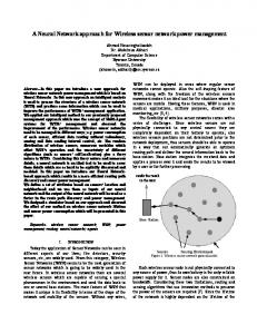
A. Channel Occupancy Time Allocation Assuming time-based fairness scheduling is enabled, each station is assigned an equal fraction of channel time in units of time slot. In such a WLAN, a station that can communicate with AP at a high channel rate can work as the proxy station for stations that can only communicate with AP at low channel rates, if they can communicate with each other at high channel rates. The time slots used for the forwarding service should come from the time slots that the client stations are alloted based on time-based fairness. Meanwhile, since transmitting data for clients consumes its energy, the proxy station should be rewarded additional time slots from its client stations for compensation. We define the fraction of channel time that a client Sq rewards its proxy Sp to keep the energy utility of Sp unchanged as the cost price (or valuation) of the proxy’s forwarding service to the client, denoted as cost(p, q). We define the fraction of channel time that a station is assigned by the time-based fairness scheduling as the assigned time of the station, and the fraction of channel time that a station can use for its own communication as the effective time of the station. We also define the fraction of channel time that a client rewards each of its proxies as its rewarding time to the proxy or the rewarded time of that proxy. The effective time of a proxy is its assigned time plus all rewarded time from its clients. The effective time of a client is its assigned time subtracting the fraction of channel time it rewards its proxies and the fraction of channel time for its data relaying (transmitting or receiving) between the AP and the immediate proxy of the client (relaying time). We further define the sum of a station’s assigned time according to time-based fairness scheduling and its rewarded time getting from its clients as the allocated time of the station, since it can use these times for its own communication and the rewarding to its proxies. Therefore, we define the utilization of the allocated time of a station Si , U (Si ), as the ratio of its effective time to its allocated time. B. Performance Gain Analysis for One-hop Relay First, we consider one client and one proxy for simplicity. Assume client station Sq is relayed by proxy station Sp . The assigned time of Sq should be divided into 3 pieces: tq = ∆t = x0,p + xp,q + ypq ,
(V.3)
where x0,p is the fraction of channel time used for data relaying between AP (S0 ) and the proxy station Sp (relaying time), xp,q is the fraction of channel time that the client station Sq is transmitting/receiving data to the proxy station (effective time), and ypq is the fraction of channel time that the client station compensates Sp (rewarding time). The utilization of xp,q . Sq ’s allocated time is U (Sq ) = ∆t The effective time of Sp is t′p = tp + ypq = ∆t + ypq ,
(V.4)
where tp is its assigned time and ypq is its rewarded time from client Sq . The utilization of Sp ’s allocated time is 1 since it
assigned time of Sp
effective time of Sp
t
Sp
ypq
t
x0, p
relaying time for Sq Sq
x0, p
xp, q
ypq
xp, q
assigned time of Sq
effective time of Sq
S0
Sp
Sq
AP
proxy
client
Fig. 1.
q
R0,q
Channel time allocation
q U(Sq )(α−1)∆tfq +1
Proof: Two constraints dictate how much time a low rate station has to offer to a high rate station: (1) every client station allocates sufficient time for the transmission and forwarding of its data; (2) the energy utility of the high rate station is unchanged. First, we have T ′ (Sq ) = x0,p R0,p = xp,q Rp,q ,
(V.5)
which means the flow rate in each hop along the forwarding path of client Sq is equal. Second, the energy utility of the proxy is unchanged, that is, the cost price of Sp serving Sq is the rewarding time of Sq to keep the energy utility of Sp unchanged E(Sp ) = E ′ (Sp ).
′ T (Sq ) = U (Sq ) =
(V.6)
Equation IV.1 gives the power consumption, throughput and energy utility of Sp when it has no clients. Denote the power consumption, throughput and energy utility of Sp when Sp serves client Sq as P ′ (Sp ), T ′ (Sp ), and E ′ (Sp ), respectively, we have ′ f P (Sp ) = Pr (1 + (α − 1)tp ), ′ q T (Sp ) = R(Sp )(∆t + yp ), (V.7) ′ E ′ (Sp ) = P ′ (Sp ) , T (Sp ) where tfp = fp (∆t+ypq )+fq x0,p +(1−fq )xp,q is the total time of proxy Sp used for data transmission. In tfp , fp (∆t + ypq ) is the time that Sp transmits its own upstream workload to AP, fq x0,p is the time that Sp forwards the upstream workload of
1 R0,p
xp,q ∆t
∆t , f 1−f 1 +(α−1)∆t( R q + Rp,qq ) + Rp,q 0,p
=
T ′ (Sq ) Rp,q ∆t
Rp,q R0,p +Rp,q +(α−1)∆t[(1−fq )Rp,q +fq R0,p ] ,
= = =
ypq
can use all its assigned time and rewarded time for its own communication. Figure 1 shows the channel time allocation in one-hop proxy forwarding. Lemma 1: In one-hop forwarding, the allocated time utilization, rewarding time, throughput gain and energy utility gain of a client Sq when it pays the cost price to its proxy Sp for the forwarding service are R0,p , U (Sq ) = R0,p +Rp,q +(α−1)∆t[f q Rp,q +(1−fq )R0,p ] fq 1−fq 2 yq = (∆t) U (Sq )Rp,q (α − 1)( R0,p + Rp,q ), p p,q gT (Sq ) = R R0,q U (Sq ), (α−1)∆tfq +1 R g (S ) = p,q . U (S ) E
Sq to AP, and xp,q is the time that Sp forwards the downstream workload of Sq to Sq . Resolving Equation V.3, V.5, and V.6, we have
tp (α − 1)(fq x0,p + (1 − fq )xp,q ) 1−f fq + Rp,qq ), ∆t(α − 1)T ′ (Sq )( R0,p
(V.8) where ypq = cost(p, q). According to Equation IV.2, for client station Sq , we have (
gT (Sq )
=
gE (Sq )
=
Rp,q R0,q U (Sq ), (α−1)∆tfq +1 Rp,q R0,q U (Sq ) U(Sq )(α−1)∆tfq +1 .
(V.9)
U (Sq ) and gT (Sq ) increase with the increase in the number of stations (the decrease of ∆t) in the WLAN. We have R Rp,q Rp,q and gT (Sq ) < Rp,q . Relaying U (Sq ) < R0,p +R p,q 0,q R0,p +Rp,q is only useful when the throughput gain gT (Sq ) > 1. Since U (Sq ) < 1, fq ≥ 0, by examining Equation V.9, we have gE (Sq ) ≥ gT (Sq ). That is, relaying can always increase the energy utility of client station as long as its throughput can be improved. For a special case when R0,p = Rp,q , we have ypq T ′ (Sq ) U (Sq ) gT (Sq ) g (S ) E
q
= = = = =
(α−1)∆t2 1 q 2+(α−1)∆t , 0 < yp ≤ 2(α+3) , ∆tR0,p R0,p ′ 2+(α−1)∆t , 0 < T (Sq ) ≤ α+3 , 2 1 1 2+(α−1)∆t , α+3 ≤ U (Sq ) < 2 , R 0,p 1 2+(α−1)∆t R0,q , R 0,p 2 1 R0,p α+3 R0,q ≤ gT (Sq ) < 2 R0,q , R0,p 1+(α−1)∆tfq 2+(α−1)∆t(1+fq ) R0,q .
(V.10)
A proxy station Sp can serve multiple clients at the same time, and these client stations may have different channel rates and different data transmitting/receiving ratios. We have the following lemma. Lemma 2: Assume station Sp provides forwarding services to k client stations, Sq1 , Sq2 , ..., Sqk (k > 1), and these client stations independently contribute their rewarding time to Sp to keep the energy utility of Sp unchanged, we have U (Sp ) gT (Sp ) g (S ) E p
= 1, P fqi = 1 + (α − 1) ki=1 T ′ (Sqi )( R0,p + = 1,
1−fqi Rp,qi
),
where T ′ (Sqi ) is the throughput of client Sqi (1 ≤ i ≤ k), with the forwarding service of Sp . Proof: It is easy to see that U (Sp ) = 1 and gE (Sp ) = 1. Since each client rewards Sp independently, similar to the last
+(1−f
(α−1)(f
x
1+(α−1)
Pk
)
)x
1 tp
p,q1 q1 q1 0,p = q yp1 = ... (α−1)(fqk x0,p +(1−fqk )xp,qk ) = , q y k
1 tp
=
p
i=1 [(fqi x0,p +(1−fq1 )xp,qk )] P qi tp + k i=1 yp
The effective time of Sp is t′p = tp + have gT (Sp )
T ′ (Sp ) T (Sp )
Pk
t′p tp
y
Pk
i=1
=
.
The flow rate of Si ’s own traffic in each hop along the forwarding path is equal, so we have
qi
1−fqi Rp,qi
T ′ (Si ) = xi0,1 R0,1 = ... = xii−2,i−1 Ri−2,i−1 = xii−1,i Ri−1,i . (V.14) For a relaying station of Si , Sj (0 < j < i), when Sj has no clients, we have P (Sj ) = Pt ∆tfj U (Sj ) + Pr (1 − ∆tfj ) = Pr [1 + (α − 1)∆tfj U (Sj )], (V.15) T (Sj ) = R(Sj )∆tU (Sj ),
).
In case R0,p = Rp,qi (1 ≤ i ≤ k), we have gT (Sp ) = 1 + (α − 1) Since k∆t =
k n
k∆t . 2 + (α − 1)∆t
(V.11)
< 1, gT (Sp ) is bounded by
where U (Sj ) = 1 when Sj has no proxy (j = 1), and U (Sj ) < 1 when Sj is relayed by other stations (1 < j < i). When Sj serves station Sj+1 , ..., Si , we have ( P ′ (Sj ) = Pr [1 + (α − 1)tfj ], Pi (V.16) T ′ (Sj ) = R(Sj )(∆t + l=j+1 ylj )U (Sj ),
α+1 . (V.12) 1 < gT (Sp ) < 2 C. A Generic Analysis for Channel Allocation in Multi-hop Forwarding A station Si that is relayed by other stations can still work as the proxy for stations of lower channel rates, and gets rewarded time from its clients. However, only a fraction of its rewarded time can be used for its own communication, since Si also needs to reward its relaying stations. We consider the relay chain S0 → S1 → · · · → Si−1 → Si starting from the AP (S0 ). In order for S1 to relay data for S2 , S1 has to keep it energy utility unchanged. After S1 decides to relay data for S2 , S2 will have a higher energy utility than that before it is relayed. S2 would like to keep this new energy utility unchanged when it decides to relay for S3 , and so on. The following Lemma describes the performance gain of a station in such scenarios. The proof basically formalizes the above process. Denote the throughput gain and energy utility gain when Si 0 has no clients as gT0 (Si ) and gE (Si ), respectively. We have the following lemma. Lemma 3: Assume each station has at most one immediate relaying station in the WLAN, and each station rewards its relaying stations independently to keep their energy utilities unchanged. For station Si that is relayed by i − 1 (i ≥ 1) stations along the path S0 → S1 → ... → Si−1 → Si , and Si has mi indirect or direct clients (Sq1 , Sq2 , ..., Sqmi ), we have ( Ri−1,i gT0 (Si ) = R0,i U (Si ), 0 gE (Si ) =
where U (Si ) = and (
gT (Si ) = gE (Si ) =
Pi Pi where tfj = fj (∆t + l=j+1 ylj )U (Sj ) + l=j+1 fl xlj−1,j + Pi Pi f j l l=j+1 (1−fl )xj,j+1 . In tj , fj (∆t+ l=j+1 yl )U (Sj ) is the time used by Sj to transmit its own workload to Sj−1 , fl xlj−1,j is the time used by Sj to transmit the upstream workload of Sl to Sj−1 , and (1 − fl )xlj,j+1 is the time used by Sj to transmit the downstream workload of Sl to Sj+1 . Considering the energy utility of Sj , we have ∆tU(Sj ) j) E(Sj ) = R(S Pr 1+(α−1)∆tfj U(Sj ) , E ′ (Sj ) =
Pi−1
1 j=1 [ Rj−1,j
gT0 (Si )(1 + 0 gE (Si )
1 +(α−1)∆t( R qj j=1 yi
P mi
∆t
)
fi j−1,j
1−fi j,j+1
+R
i ≥ 1, i ≥ 1,
)]
Pi j R(Sj ) (∆t+ l=j+1 yl )U(Sj ) . Pr 1+(α−1)tfj
The energy utility of Sj should be unchanged, that is, E(Sj ) = E ′ (Sj ). By substituting E(Sj ) and E ′ (Sj ), we have (α − 1)fj + (α − 1)fj +
1 = ∆tU(Sj ) P 1+(α−1) il=j+1 (fl xlj−1,j +(1−fl )xlj,j+1 ) P , (∆t+ il=j+1 ylj )U(Sj )
Simplifying P the equation, we have 1 ∆t
=
(α−1)
i l l l=j+1 (fl xj−1,j +(1−fl )xj,j+1 ) Pi j l=j+1 yl
.
Since each station Sl (j + 1 ≤ l ≤ i) rewards time slots to Sj independently, it is easy to prove
Ri−1,i (α−1)∆tfi +1 R0,i U (Si ) U(Si )(α−1)∆tfi +1 ,
1+Ri−1,i
1−fq
i ti = (xi0,1 + ...+ xii−2,i−1 )+ xii−1,i + (y1i + ...+ yi−1 ). (V.13)
ypqi . Thus, we
p = 1 + i=1 tp P fqi + = 1 + (α − 1)∆t ki=1 T ′ (Sqi )( R0,p
=
fq
q
j + Ri,i j ), T ′ (Sqj ) is where yi j = ∆t(α − 1)T ′ (Sqj )( Ri−1,i j the throughput of Sqj when it is forwarded by Si , and Sij is the next hop station of Si to reach Sqj . Proof: For station Si (i > 1) that is relayed by stations S1 , ..., Si−1 , we have
formula in Equation V.8, we have
(α − 1)(fl xlj−1,j + (1 − fl )xlj,j+1 ) 1 . = ∆t ylj
,
Thus, we have ylj
= =
∆t(α − 1)(fl xlj−1,j + (1 − fl )xlj,j+1 ) fl l + R1−f ), ∆t(α − 1)T ′ (Sl )( Rj−1,j j,j+1
(V.17)
where T ′ (Sl ) is the throughput of Sl when it is served by Sj and T ′ (Sl ) = Rl−1,l × tl U (Sl ), where U (Sl ) is the allocated time utilization of Sl . When Si has no clients, we have ti = ∆t. Considering Equation V.13, V.14, and V.17, for station Si , we have U (Si ) = 1+Ri−1,i
′
T (Si ) Ri−1,i ti
S2
Access Point
=
Pi−1
1 j=1 [ Rj−1,j
relayed by
channel rate
S1
-
R0, 1
S2
-
R0,2
S3
-
R0, 3
S4
S3
R0, 4
S5
S3
R0, 5
S6
S3
R0, 6
S7
S3
R0, 7
S3
1 +(α−1)∆t( R
fi j−1,j
1−fi +R j,j+1
)]
.
S1
(V.18)
Accordingly, we get Ri−1,i ti U(Si ) R T ′ (Si ) 0 = Ri−1,i U (Si ), R0,i ∆t gT (Si ) = T′(Si ) = 0,i Ri−1,i E (Si ) P (Si ) 0 gE (Si ) = E(Si ) = R0,i U (Si ) P ′ (Si ) Ri−1,i U (Si ) (α−1)∆tfi +1 . = R0,i
S0
mobile station
station
S4
Forwarding Table hop
station
channel rate
1
S3
R0, 3
2
S5
R3, 5
3
self
R5, 6
Fig. 2.
hop
station
channel rate
1
S3
R0, 3
2
self
R3, 5
3
S6
R5, 6
S7
R5, 7
S5
S6
S7
Multi-hop forwarding structure
U(Si )(α−1)∆tfi +1
(V.19) When Si has mi clients Sq1 , ..., Sqmi , since each client rewards Si time slots independently, new throughput is Pmi the q T ′′ (Si ) = U (Si )Ri−1,i (∆t + j=1 yi j ). The performance gain becomes ( Pmi qj ′′ (Si ) j=1 yi 0 = g (S )(1 + ) i ≥ 1, gT (Si ) = TT (S i T ) ∆t i 0 gE (Si ) = gE (Si ) i ≥ 1, q
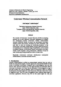
where yi j follows Equation V.17. The above analysis of the channel allocation for one-hop and multi-hop forwarding shows the performance gains of low channel rate clients and high channel rate proxies. Specifically, we show that a high rate station will increase its throughput even with its energy utility unchanged, providing a strong incentive for the forwarding service. VI. S YSTEM D ESIGN In this section, we describe the system design of the multi-hop forwarding service. The proposed system consists of three major components: a proxy selection algorithm, a token-based energy-aware channel scheduling algorithm, and a multi-hop forwarding algorithm. The proxy selection algorithm runs on the AP, choosing relay proxies for stations with low channel rates. The energy-aware channel scheduling algorithm also runs on the AP, arbitrating channel time allocation and ensuring time-based and max-min fairness among stations. The multi-hop forwarding algorithm is a distributed algorithm running on both the AP and each station, in order to coordinate intermediate stations along the forwarding path and provide reliable communication at the MAC layer. The three algorithms work together to enable the data forwarding among stations in a WLAN. As shown in Figure 2, stations in the WLAN are organized into a tree rooted at the AP for the multi-hop forwarding service. Each non-root node of the tree represents a station, and the weight of each edge represents the channel rate between two nodes. The AP (root) maintains the topology and the weights of edges of the forwarding tree. Each station maintains the information about its children and predecessors, and the weight of each edge along the path. Note that the height of
the forwarding tree should be small (typically two or three in 802.11b). The main reason for this is that the data forwarding along each hop requires the occupancy of channel resources (spatial reuse is difficult in WLANs). With the increase in the number of forwarding hops, the improvement of a client’s throughput decreases rapidly. Moreover, due to the possible mobility of stations, it is much easier to maintain a short tree than a tall one. A. Proxy Selection and Association With the channel time compensation, the forwarding service is profitable and thus becomes a kind of resource that stations want to compete for. This is significantly different from previous multi-hop routing algorithms in ad hoc networks. To ensure the fairness of this competition, we propose an auction-based mechanism for proxy selection. Our proxy selection algorithm runs on the AP, which works as the auctioneer. When a station Sq is working at a low channel rate to communicate with the AP, it broadcasts a sequence of SFP (search for proxy) messages with different channel rates. Upon receiving an SFP, each high channel rate station computes the expected throughput gain it can provide to Sq and the cost price based on Lemma 3, then bids for the forwarding service with the cost price. Upon receiving an SFP, the AP collects the bids from all bidders within the bidding time, and then selects the station that can provide the largest throughput gain for Sq as the proxy. A client would always like to pay less and get more, while a proxy would always like to being paid more and serve less. In our mechanism design, the dominant strategy for all bidders—the “best” strategy they can expect—should be to bid with the cost price of their services. The second price sealed bid auction rule [23] can be applied to provide such a dominant strategy and finish the auction in one bidding round. In this mechanism, station Sq will pay the proxy at the price of the bidder who offers the second largest throughput gain (please refer to our technical report [8] for a detailed description of the auction mechanism). When the proxy is selected, the AP sends (or piggybacks) the MAC address of the proxy and the corresponding price to Sq . Then Sq sends a RFR (request for relay) message to the
arriving tokens from AP
1/r sec
bucket depth = 3
1/r sec
3/r sec
X arriving packets
to wireless channel
Fig. 3. Token bucket: the AP distributes tokens in a rate r (one round per 1/r seconds)
proxy, and the proxy acknowledges the request and reports to the AP to commit the proxy association. When the client does not need data forwarding any longer, it sends a notification to the AP directly through the low-rate channel to cancel the forwarding service. Many high channel rate stations may compete with each other to get more rewarded time slots to improve their own throughput. The AP needs to balance the profits among proxy candidates that can provide the same forwarding services in a WLAN. For example, if two stations can provide the same throughput gain for Sq , the AP should favor the station with less throughput as the proxy of Sq . Other factors, such as the history of activity and mobility of the proxy candidates, may also be taken into consideration for proxy selection. B. Channel Allocation and Scheduling The channel scheduling and the forwarding coordination can be easily implemented in 802.11 WLANs under PCF (point coordination function) with polling MAC mechanism. However, most 802.11 commercial products only support DCF (distributed coordination function) MAC control. In what follows, we describe our system design for 802.11 WLAN under the DCF MAC mechanism. In the proposed system, the channel is allocated in units of time slot, same as the unit of station’s back-off time for PHY medium access (50 µs for FHSS and 20 µs for DSSS). As shown in Figure 3, the time slot allocation is performed by the AP based on the token bucket model. Each station is assigned a certain number of tokens for use in channel contention. A station competes for channel only when it has available tokens. At regular intervals, the AP evenly distributes tokens to each station, ensuring time-based fairness. When the bucket of a station is full, the overflowing tokens are returned to AP, and are re-distributed equally to other stations to ensure max-min fairness. The token bucket shapes the frame transmission of a station at a constant rate in the long run, while allowing bursty frame transmission of a station in the short term. The tokens can be distributed individually or be piggybacked within the data/control frames to stations. A station transmits data frames only when it has enough tokens. Similarly, the AP buffers data frames for stations without tokens, and postpones their data transmission to the next round of time-slot allocation. Thus, the number of tokens a station holds determines whether it is qualified for channel
competition. Meanwhile, channel contention is fair for those stations with tokens. Therefore, the channel occupancy time of a station is dependent on the token allocation scheme in the long term, although it is non-deterministic in the short term. We use the similar method as that in [27] to compute the channel occupancy time of a station. For each station, a token counter is maintained at this station and the AP, respectively. Upon receiving/sending a data frame from/to the AP, the station deducts the corresponding tokens from its token counter. At the same time, the AP deducts the same number of tokens of that station. In 802.11 protocol, the number of retries that a sender transmits a frame is included in the frame header that the receiver gets. However, current hardware does not return the number of retries when the frame is successfully transmitted. Thus, the sender cannot accurately compute the number of tokens used for data transmission, and the two counters may be inconsistent. To minimize this effect, the receiver piggybacks the number of tokens that are used for the last data transmission of its peer in the data frame, and the peer adjusts its token counter accordingly. To simplify token management, a proxy station does not maintain token counters for its clients. Once a client associates to the proxy, the tokens, including those that the client should reward its proxy and those that are used to receive/forward data frames for the client, are delivered to the proxy directly by the AP during the token distribution. Correspondingly, the same number of rewarding tokens is deducted from the token counter of the client by the AP. Once the client cancels the forwarding service, the proxy automatically suspends the data forwarding at the next round of token distribution, because the AP will no longer convey the client’s rewarding tokens. C. Multi-Hop Forwarding 1) Basic Mechanism: To support multi-hop forwarding, each data frame is appended with two fields indicating the source and destination MAC addresses of the frame, respectively. Each station maintains a forwarding table as shown in Figure 2. Upon receiving a data frame, the station compares the destination MAC address with its own MAC address. If they are different, the station looks up the MAC address for the next-hop station in the forwarding table. Then it modifies the destination address of the frame header and forwards it to the next-hop station. The forwarding table also records the uplink channel rates of the station’s predecessors, in order to compute the cost price for the forwarding service it provides its clients, and throughput gains its clients can achieve. 2) Forwarding Path Maintenance: The channel rates along the forwarding path and between the client and the AP may change with the mobility of stations or signal instability. Furthermore, the forwarding path may even be broken, due to hardware failure, signal error (or interference), and the mobility of proxy stations. To cope with the possible change of channel rates, each client periodically re-evaluates the forwarding service. If the service quality is significantly degraded, it re-broadcasts SFPs for a new proxy.
VII. I MPLEMENTATION AND E XPERIMENTAL E VALUATION This section presents a prototype implementation of our proposed scheme and its experimental evaluation. Our purpose is twofold: (1) to demonstrate that our data forwarding mechanism is feasible under the framework of the current IEEE 802.11 protocol; and (2) to validate its efficacy in significantly improving the throughput and energy utility for stations in the WLAN. A. Prototype Implementation We have implemented a prototype of the proposed scheme and evaluated it on our testbed, which includes an Access Point and six mobile stations. The AP is a desktop PC equipped with a NetGear MA311 802.11b PCI wireless adaptor running Linux kernel 2.4.20. The mobile stations are six HP laptop computers, each equipped with a NetGear MA401 802.11b PCMCIA wireless adaptor running Linux kernel 2.4.20. One of the six works as the proxy, the others work as the clients. All wireless adaptors in the AP and mobile stations use the Intersil Prism2 chipset. We have modified the HostAP Linux driver for Prism2/2.5/3 [2] as the driver of our Access Point. The AP maintains the forwarding structure for each station associated to it, as described in Section VI. The bidding time for proxy selection is set to 50 ms and the token distribution interval is set to 100 ms. Each token denotes 20 µs channel occupancy time. To implement the token distribution, the HostAP driver maintains the number of available tokens owned by each mobile station that is currently associated to the AP. In each round of the token distribution, the HostAP driver first evenly allocates tokens based on the number of stations, then transfers the rewarding tokens from each client to its proxy based on their service agreement. We have also modified the ORiNOCO Linux driver 0.15rc2 for wireless cards [3] as the driver of our proxy and client
6 5 throughput (Mbps)
3) Power Management in Multi-hop Forwarding: Most existing power saving solutions [4], [16] utilize heuristic algorithms to adapt the sleep behavior of a WNI with its network activities. When a station has no network traffic, it will still be up for a while before it goes to sleep based on the prediction of its network activity. The station may also change its waking period adaptively to save the energy consumption on beacon listening. In our scheme, each station has the flexibility to set its own power saving policy. Any station that wants to sleep needs to send a request to the AP, so that the AP can buffer the incoming data frames for it. The sleep request of a client is sent to the AP at a low channel rate directly. When a proxy decides to switch to power saving mode, it notifies its immediate clients first. If any child of the proxy has clients, the notification will be propagated recursively. Upon receiving the ACK from all its clients, the proxy sends a request to the AP, and shifts to power saving mode. Then, its clients (immediate or non-immediate) search for new proxies.
4 3 2 1 0
Fig. 4. rates
1 Mbps
2 Mbps 5.5 Mbps 11 Mbps channel rate
The effective bandwidth of 802.11b WLAN under different channel
stations. Inside the driver, we have implemented a simple multi-hop forwarding protocol. B. Experimental Evaluation To evaluate the implemented prototype, we have conducted extensive experiments on our testbed with respect to FTP-like and Web-like workload, respectively. Due to page limitations, we only present the results of FTP-like workload (please refer to our technical report [8] for a detailed evaluation of Web-like workload). 1) Performance Baseline Measurement: The ideal channel rate of IEEE 802.11 WLAN cannot be achieved in reality, due to the overhead of control frames, inter-frame spaces, physical and MAC layer headers, channel contention, and possible data losses. Therefore, we first measure the effective throughput of a WNI as the baseline for performance comparisons. In this evaluation, we first set up a small 802.11b WLAN that consists of an AP and a mobile station. A large file (about 1 GB) is downloaded from the AP to the station to measure the user level throughput under different channel rates. Figure 4 shows the effective bandwidth of the 802.11b WLAN under channel rates of 1 Mbps, 2 Mbps, 5.5 Mbps, and 11 Mbps, respectively. The higher the channel rate is, the less efficient the channel utilization is. The reason is that all physical layer headers are transmitted at the lowest channel rate in the 802.11b protocol, in order to ensure that all stations in a WLAN can listen to the channel for collision avoidance. However, the diversity of user level throughput under different channel rates is still large enough to benefit low channel rate users through data forwarding. In WLANs supporting more levels of channel rates such as 802.11a, multi-hop data forwarding would have greater potential to improve the system performance. 2) Experiments on FTP-like Workload: We implement four channel allocation protocols as listed in Table II and compare their throughput and energy utility with a FTP-like data transmission workload. In these schemes, DCF denotes the normal DCF MAC in a 802.11b WLAN, and TBF denotes the time-based fairness channel contention mechanism proposed in [27]. SFW denotes our proposed mechanism, meaning selfish multi-hop forwarding, in which the client pays the cost price for the forwarding service (since there is only one proxy). In order to show the advantage
overall 3.81
1
overall 1.35 DCF
Q TBF SFW channel allocation scheme
P
overall 1.86 overall 1.76
2 1 0
overall 0.67 DCF
Q TBF SFW channel allocation scheme
P
TBF−FW
(a) Channel rates between stations: Q-AP, 1 M; P-AP, 11 M; Q-P, 11 M Fig. 5.
1.5
Q (1 M) P (5.5 M) overall 2.03
overall 2.71
overall 2.63
1 overall 1.25
Q
0.5 DCF
TBF SFW channel allocation scheme
P
TBF−FW
2 1.5
Q (1 M) overall 1.01 P (5.5 M)
overall 1.28
overall 1.24
1 overall 0.63
Q
0.5 0
DCF
TBF SFW channel allocation scheme
P
TBF−FW
(b) Channel rates between stations: Q-AP, 1 M; P-AP, 5.5 M; Q-P, 11 M
The throughput and energy utility of stations under different channel allocation schemes (1 proxy and 1 client)
TABLE II C HANNEL ALLOCATION SCHEME Scheme DCF TBF SFW TBF-FW
2
0
TBF−FW
3 Q (1 M) overall 1.46 P (11 M)
throughput (Mbps)
station Q to station P: 11 M
overall 3.99
2
0
energy utility (Mb/J)
Q (1 M) P (11 M) overall 2.93
energy utility (Mb/J)
throughput (Mbps)
station Q to station P: 11 M 3
Scheme Description 802.11 DCF MAC (without data forwarding) time-based fairness scheduling (without data forwarding) selfish forwarding under TBF scheduling data forwarding under TBF scheduling
of our proposed channel time compensation mechanism, we also implement data forwarding under time-based fairness for comparison, called TBF-FW. In this mechanism, each station is assigned equal channel time to ensure time-based fairness, and the proxy voluntarily forwards data for its clients using the channel time of its clients, without any time slot rewarded. Note that this is a phantom mechanism just for comparison, neither proposed nor implemented before. In the experiments, we simultaneously download a large file from the HostAP machine to the proxy and client stations, respectively. The throughput is measured by recording the data volume transfered between each client and its proxy (or the proxy and the AP) under different channel allocation schemes. The energy consumption on data transmitting is computed as the product of the data transmission time of physical frames and the power consumption of the wireless card in the transmitting mode (provided by the manufacturer). The energy consumption on receiving/listening is computed in a similar way. We conduct experiments for the one-hop forwarding case, where the WLAN consists of 1 AP, 1 proxy (denoted by P), and multiple clients (denoted by Q) varying from 1 to 5. Assuming all clients have the same channel rate, there are eight possible combinations for the data forwarding service: • the channel rate is 1 M or 2 M between Q-AP, 11 M between P-AP, and 11 M between Q-P; • the channel rate is 1 M or 2 M between Q-AP, 5.5 M between P-AP, and 11 M between Q-P; • the channel rate is 1 M or 2 M between Q-AP, 11 M between P-AP, and 5.5 M between Q-P;
•
the channel rate is 1 M or 2 M between Q-AP, 5.5 M between P-AP, and 5.5 M between Q-P.
Each experiment is repeated three times. Figures 5, 6, and 7 show the performance in a WLAN with 1 AP, 1 proxy, and 1, 3, and 5 clients, respectively. Due to page limitations, only part of results are presented (other results are similar). In the figures, the number on the top of the bar group denotes the overall throughput (in Mbps) or the overall energy utility (in Mb per Joule) of the proxy and client stations in the WLAN. We also present the corresponding performance of DCF and TBF for comparisons. The performance of phantom TBF-FW is presented as white bars. The results can be summarized as follows. SFW has the highest overall performance for both throughput and energy utility, while DCF has the worst overall performance. By enforcing time-based fairness, TBF improves the performance of high channel rate stations but decreases the performance of low channel rate stations. TBF-FW improves the throughput of low channel stations (clients) by data forwarding, but significantly decreases the energy utility of the forwarding station (proxy), which the proxy is unwilling to do. So the phantom TBF-FW scheme, though simple and effective for low channel rate stations, is not likely feasible in practice. In contrast, in our proposed forwarding scheme, the proxy gets additional channel time compensation from its clients, resulting in the improvement of its own throughput without decreasing its energy utility, and thus providing a strong incentive for the forwarding service. The client stations sacrifice a few channel time tokens for the forwarding service, but the overhead is minor. For example, as shown in Figure 6(a), the client throughput of SFW is 138% higher than that of DCF, more than 2 times over that of TBF, and about 93% of that of TBF-FW, while the proxy throughput of SFW is more than 5 times over that of DCF, and 23% higher than those of TBF and TBF-FW. The proxy energy utility of SFW is more than 4 times over that of DCF, and is same as that of TBF. On the other hand, compared with SFW, the proxy energy utility of TBF-FW is 20% lower than
overall 1.85
overall 3.17
1 0.5 0
energy utility (Mb/J)
station Q to station P: 11 M
overall 3.32
Q
overall 0.98 DCF
TBF SFW channel allocation scheme
P
overall 0.78 overall 0.75
1 0.5
Q
overall 0.25 0
DCF
TBF SFW channel allocation scheme
P
TBF−FW
(a) Channel rates between stations: Q-AP, 1 M; P-AP, 11 M; Q-P, 11 M Fig. 6.
1
Q (1 M) P (5.5 M) overall 1.40
overall 0.96 DCF
energy utility (Mb/J)
TBF SFW channel allocation scheme
P
TBF−FW
Q (1 M) overall 0.35 P (5.5 M)
overall 0.57 overall 0.55
0.5 overall 0.24 0
DCF
Q TBF SFW channel allocation scheme
P
TBF−FW
(b) Channel rates between stations: Q-AP, 1 M; P-AP, 5.5 M; Q-P, 11 M
overall 3.07 overall 1.49
overall 2.96
0.5 Q
overall 0.90 DCF
TBF SFW channel allocation scheme
P
overall 0.49 overall 0.47
0.5 Q
overall 0.15 DCF
TBF SFW channel allocation scheme
P
TBF−FW
(a) Channel rates between stations: Q-AP, 1 M; P-AP, 5.5 M; Q-P, 11 M
1
Q (2 M) P (5.5 M) overall 1.77
0.5
overall 2.25
overall 1.61 0
TBF−FW
1 Q (1 M) overall 0.25 P (11 M)
throughput (Mbps)
station Q to station P: 11 M
energy utility (Mb/J)
throughput (Mbps)
1
Fig. 7.
Q
1
station Q to station P: 11 M Q (1 M) P (11 M)
0
overall 2.31
The throughput and energy utility of stations under different channel allocation schemes (1 proxy and 3 clients)
1.5
0
overall 2.37
0.5
0
TBF−FW
1.5 Q (1 M) overall 0.46 P (11 M)
throughput (Mbps)
1.5
Q (1 M) P (11 M)
energy utility (Mb/J)
throughput (Mbps)
station Q to station P: 11 M 2
DCF
overall 2.21 Q
TBF SFW channel allocation scheme
P
TBF−FW
0.8 0.6
Q (2 M) P (5.5 M) overall 0.29
overall 0.36 overall 0.35
0.4 overall 0.27 0.2 0
Q DCF
TBF SFW channel allocation scheme
P
TBF−FW
(b) Channel rates between stations: Q-AP, 2 M; P-AP, 5.5 M; Q-P, 11 M
The throughput and energy utility of stations under different channel allocation schemes (1 proxy and 5 clients)
that of TBF without any throughput improvement for the forwarding service. Furthermore, with our proposed SFW, the overall performance in the WLAN is also better than that of TBF-FW. These results evidence that our proposed scheme not only provides a strong incentive for data forwarding, but also balances the trade off between the performance of individual stations and the entire WLAN. Figure 8(a) shows the proxy throughput gain in SFW (the proxy throughput of SFW over that of TBF) with the increasing number of clients in the WLAN. In this experiment, the proxy (working at 11 Mbps channel rate with the AP) serves all other stations (working at 1 Mbps with the AP and 11 Mbps with the proxy) in the same WLAN. The throughput gain of the proxy increases with the number of clients it serves. With channel time compensation, even in 1 client and 1 proxy case, the proxy throughput can still be improved by 14% over TBF. Figure 8(b) shows the proxy energy utility gain in TBFFW (the proxy energy utility of TBF-FW over that of TBF) in the same circumstances as above. The energy utility gain is less than 1, meaning it is smaller than that in TBF. Figure 8(b) also indicates that in TBF-FW, the proxy may have to consume more than 22% energy for its clients, which could
prevent the proxy from providing such service. VIII. C ONCLUSION In this paper, we aim to (1) address the throughput degradation induced by low channel rate stations in a WLAN, and (2) utilize the inevitable energy waste in channel listening during a communication session. We characterize energy efficiency as energy per bit, instead of energy per second. Utilizing idle communication power, we present a data forwarding mechanism and an energy-aware token rewarding scheme to supplement the IEEE 802.11 protocols. In data forwarding, a high channel rate station forwards data for a low channel rate station, resulting in a significant improvement of its throughput. To give high channel rate stations an incentive to be proxies, we design an energy-aware token rewarding scheme, in which low channel rate stations compensate for proxies with additional time slots. Thus, a proxy can also improve its own throughput without compromising its energy efficiency. We have presented a mathematical model to guide the protocol design, and have proposed algorithms for proxy selection, channel allocation and scheduling, and data forwarding in
1.3
1
0.95 proxy energy utility gain
proxy throughput gain
1.25
1.2
1.15
1.1
0.85
0.8
1.05
1
0.9
1
2
3 4 number of clients
5
(a) Improvement of proxy throughput gain in SFW Fig. 8.
0.75
1
2
3 4 number of clients
5
(b) Reduction of proxy energy utility gain in TBFFW
Performance gain of proxy with different number of clients
the IEEE 802.11 WLAN. To evaluate our proposed scheme, we have implemented a prototype of the proposed system by modifying the HostAP driver running on a Linux PC serving as an Access Point, and ORiNOCO Linux driver for wireless cards. We have conducted a set of experiments on our testbed. The experimental results show that the proposed data forwarding and channel access time compensation schemes significantly improve the system performance of the entire WLAN. ACKNOWLEDGMENT We would like to thank William L. Bynum for his constructive comments and suggestions. This work is partially supported by the National Science Foundation under grants xxx. R EFERENCES [1] http://www.cisco.com/en/US/products/hw/wireless/. [2] Host AP driver for intersil prism2/2.5/3, hostapd, and WPA supplicant. http://hostap.epitest.fi/. [3] The Linux ORiNOCO driver. http://www.nongnu.org/orinoco/. [4] M. Anand, E. Nightingale, and J. Flinn. Self-tuning wireless network power management. In Proc. of ACM MOBICOM, San Diego, CA, Sept. 2003. [5] A. Bakre and B. Badrinath. I-TCP: Indirect TCP for mobile hosts. In Proc. of IEEE ICDCS, Vancouver, Canada, May - June 1995. [6] H. Balakrishnan, S. Seshan, and R. Katz. Improving reliable transport and handoff performance in cellular wireless networks. ACM Wireless Networks, 1(4):469 – 481, 1995. [7] K. Brown and S. Singh. M-TCP: TCP for mobile cellular networks. ACM SIGCOMM Computer Communication Review, 27(5):19 – 43, 1997. [8] L. Guo, X. Ding, H. Wang, Q. Li, S. Chen, and X. Zhang. Exploiting idle communication power to improve wireless network performance and energy efficiency. Technical Report, http://www.cse.ohiostate.edu/∼lguo/idle-comm-power-techreport.pdf. [9] M. Heusse, F. Rousseau, G. Berger-Sabbatel, and A. Duda. Performance anomaly of 802.11b. In Proc. of IEEE INFOCOM, San Francisco, CA, May 2003. [10] G. Holland, N. H. Vaidya, and P. Bahl. A rate-adaptive MAC protocol for multi-hop wireless networks. In Proc. of ACM MOBICOM, Rome, Italy, July 2001. [11] H. Hsieh, K. Kim, Y. Zhu, and R. Sivakumar. A receiver-centric transport protocol for mobile hosts with heterogeneous wireless interfaces. In Proc. of ACM MOBICOM, San Diego, CA, Sept. 2003.
[12] H. Hsieh and R. Sivakumar. On using the ad-hoc network model in cellular packet data networks. In Proc. of MOBIHOC, Lausanne, Switzerland, June 2002. [13] H. Kim and J. Hou. Improving protocol capacity with model-based frame scheduling in IEEE 802.11-operated WLANs. In Proc. of ACM MOBICOM, San Diego, CA, Sept. 2003. [14] K. Kim and K. G. Shin. Improving TCP performance over wireless networks with collaborative multi-homed mobile hosts. In Proc. of ACM MOBISYS, Seattle, WA, June 2005. [15] D. Kotz, C. Newport, and C. Elliott. The mistaken axioms of wirelessnetwork research. Technical Report TR2003-467, Computer Science, Dartmouth College, July 2003. [16] R. Krashinsky and H. Balakrishnan. Minimizing energy for wireless Web access with bounded slowdown. In Proc. of ACM MOBICOM, Atlanta, GA, Sept. 2002. [17] R. Kravets and P. Krishnan. Power management techniques for mobile communication. In Proc. of ACM MOBICOM, Dallas, TX, 1998. [18] R. Kravets and P. Krishnan. Application-driven power management for mobile communication. Wireless Networks, 6(4):263–277, 2000. [19] S. Lee, S. Banerjee, and B. Bhaatcharjee. The case for a multi-hop wireless local area network. In Proc. of IEEE INFOCOM, Hong Kong, China, Mar. 2004. [20] S. Lu, V. Bharghavan, and R. Srikant. Fair scheduling in wireless packet networks. IEEE/ACM Transactions on Networking, 7(4):473–489, 1999. [21] H. Luo, R. Ramjee, P. Sinha, L. Li, and S. Lu. UCAN: a unified celluar and ad-hoc network architecture. In Proc. of ACM MOBICOM, San Diego, CA, Sept. 2003. [22] L. S. C. of the IEEE Computer Society. Wireless LAN medium access control (MAC) and physical layer (PHY) specifications. Technical Report IEEE Std 802.11, the Institute of Electrical and Electronics Engineers, Inc., 1999. [23] M. J. Osborne and A. Rubinstein. A Course in Game Theory. The MIT Press, Cambridge, MA, 1994. [24] B. Sadeghi, V. Kanodia, A. Sabharwal, and E. Knightly. Opportunistic media access for multirate ad hoc networks. In Proc. of ACM MOBICOM, Atlanta, GA, Sept. 2002. [25] E. Shih, P. Bahl, and M. Sinclair. Wake on wireless: An event driven energy saving strategy for battery operated devices. In Proc. of ACM MOBICOM, Atlanta, GA, Sept. 2002. [26] M. Stemm and R. Katz. Measuring and reducing energy consumption of network interfaces in hand-held devices. IEICE Transactions on Fundamentals of Electronics, Communications, and Computer Science, Special Issue on Mobile Computing, E 80-B(8):1125–1131, 1997. [27] G. Tan and J. Guttag. Time-based fairness improves performance in multi-rate WLANs. In Proc. of USENIX Annual Technical Conference, Boston, MA, June 2004. [28] N. H. Vaidya, P. Bahl, and S. Gupta. Distributed fair scheduling in a wireless LAN. In Proc. of ACM MOBICOM, Boston, MA, Aug. 2000. [29] H. Zhu and G. Cao. rDCF: A relay-enabled medium access control protocol for wireless ad hoc networks. In Proc. of IEEE INFOCOM, Miami, FL, Mar. 2005.