Within the DESIRE project, RFID was investigated for platform localization in large operation ... InMach Intelligente Maschinen GmbH, Ulm, Germany e-mail: ...
Exploiting RFID Capabilities Onboard a Service Robot Platform Thomas K¨ampke, Boris Kluge, and Matthias Strobel
Abstract. The potential of RFID (radio frequency identification) technology is analyzed in the context of service robots. Various concepts that differ by operation frequency (LF, HF, UHF) and, thus, by range are analyzed. Typically, the service robot application which is to be supported by RFID, preselects the frequency band by range requirements. Within the DESIRE project, RFID was investigated for platform localization in large operation areas as well as for object identification at small distances. To enable this investigation, an electronic system was designed, built and integrated into the DESIRE platform that supports multiple antenna control. Detection zones of objects, equipped with UHF-RFID tags, were estimated under lab conditions and for onboard scenarios. In particular, strengths and weaknesses of UHF-RFID object identification at far distances and in the presence of interfering signals are discussed. This lead to one scenario in which the robot grasps an object, moves and rotates it in reading distance to the antenna mounted at the robot torso. The service robot can thus perceive object information that complements information from other sensor modalities like vision.
1 Introduction Radio frequency identification (RFID) technology has received a boost since passive transponders or, short, tags have come of age. These transponders use only the energy of incoming radio waves thus not necessitating own energy supply. Information which is stored in the tags is transmitted, upon demand, to a reader. In addition, some reading devices can write information into the tags. Typically in robotics, platform localization is addressed by using short range HF tags and, object identification can be addressed by using UHF tags with longer range. Thomas K¨ampke · Boris Kluge · Matthias Strobel InMach Intelligente Maschinen GmbH, Ulm, Germany e-mail: {kaempke,kluge,strobel}@inmach.de E. Prassler et al. (Eds.): Towards Service Robots for Everyday Environ., STAR 76, pp. 215–225. c Springer-Verlag Berlin Heidelberg 2012 springerlink.com �
216
T. K¨ampke, B. Kluge, and M. Strobel
The first wave of RFID application onboard service robots has been concerned with self-localization by tags located underneath the floor. The pattern of these floor tags is supposed to be known to the robot or it can be acquired during a training phase. One or more reading antennas are directed to the floor. Positions of the moving robot are inferred from aligning actual tag readings with the tag pattern. Proposals of various degrees of maturity have been made [5]. But, since tags may fail for some reason or be destroyed during deployment, localization algorithms must cope with missing tag sensations. The work [6] contributed to this issue of robust usability. However, tag deployment issues for floors including cost are seldom considered. In a straightforward extension of this concept, robots can share information by writing into tags. More recent work proposes to investigate or investigates RFID-enabled forms of robot interaction in medical environments [3] and everyday environments [12]. RFID-supported person tracking [4] is one example, others are interaction with people wearing transponders and the manipulation of labeled objects such as light switches [2]. The work undertaken here also falls into this category. Yet it is dual to mere scanning of a room or another volume from steerable antennas at fixed locations [8]. It is feasible to combine RFID with other sensor modalities like computer vision within and outside the robotics area as, for example, for object identification and position determination on desks [10]. These applications are close to asset tracking, the original field of RFID, comp. [7]. In all cases and scenarios a significant benefit of using RFID technology is its ability to post information to a service robot which were incomprehensible otherwise. Examples are expiration dates of food, time stamps indicating the most recent operation on an object as well as coordinates and the stiffness of objects. Use of RFID also allows the identification of an individual object instead of only recognizing its type or class.
2 Lab Tests All tests for object identification by RFID onboard service robots were run with passive tags and UHF equipment. UHF is the only frequency band which promises sufficiently large reading distances. Reading range as function of the frequency in this band – all other things remaining equal – is reported to become maximal around 880 MHz [9]. Typical passive tags with integrated antenna are shown in figure 1. All lab tests were performed with pure RFID equipment meaning without objects to which tags might be attached. The presence of metal and liquids is known to affect range [1]. A reader antenna with circular polarization was selected in order to obtain directional independence of readings. A sample is shown in figure 2. The lab tests were performed with two readers to explore the effect of different power levels and to compare a self-contained device to an OEM component. All tag positions were arranged in one plane parallel to the reader antenna at a 20cm grid. From an initial position, the tag plane was shifted by multiples of 20cm
Exploiting RFID Capabilities Onboard a Service Robot Platform
217
to increase distances to the reader antenna. Reading volumes or reading lobes of complete tag-reader combinations are shown in figures 4 and 5. Range differences between the two combinations are mainly due to power differences rather any other reader properties or external circumstances. Since single reading attempts may fail, each tag position was probed for 10 seconds and reading volumes refer to the absolute frequency of successful readings. Without disturbances, reading distances of several meters are possible. This is often understood as medium-range in RFID technology. Reading lobes may exhibit certain non-monotonicites. Thus, as shown, readability is not monotone in the distance between the antennas of reader and tag. Similar effects can be demonstrated for directional antenna changes at constant distance.
Fig. 1 UHF-RFID tags operating at 865 to 928 MHz. Tag by Avery Denison (left) with Monza integrated chip by Impinji. Size 152 × 38 mm. Use storage capacity 96 bit. Wisteq tag (right) of size 85 × 54 mm (credit card format) with NXP chip.
Fig. 2 UHF-reader antenna for circular polarization at 8.5 dBi. Size 305 × 25 mm.
218
T. K¨ampke, B. Kluge, and M. Strobel
Fig. 3 RFID readers by Sirit (left) with maximum power of 2W. Skyetek reader (right) with maximum power of 500 mW. The Sirit reader is the significantly larger of the two readers.
Fig. 4 Slightly irregular readability volume of the Avery Denison tag from figure 1 and the Sirit reader from figure 3. The antenna center is located at (0, 0, 0), all axes are scaled in cm.
Exploiting RFID Capabilities Onboard a Service Robot Platform
219
Fig. 5 Constellation similar to figure 4 with M9 reader by Skyetek.
Fig. 6 Horizontal cross-section of lobe from figure 4. The colors code successful readings from a 10 sec. interval with the color at the top of the bar indicating the maximum.
220
T. K¨ampke, B. Kluge, and M. Strobel
Tags with smaller antennas reduce range and may even exhibit disconnected reading volumes.
3 Integration on a Platform Several design aspects have to be considered when a service robot platform shall be enhanced with RFID sensing capabilities, ranging from the physical placement of the antenna through the interface presented to other software components.
3.1 Antenna Integration The antenna is the device which directly interacts with the RFID transponder, thus care needs to be taken about its optimal design, placement, and other potentially interfering devices or materials in its vicinity. Since the working principle of LF (125 kHz) and HF (13.56 MHz) RFID systems is inductive coupling (i.e. antenna and transponder can be considered as primary and secondary coils of a transformer), it is crucial to keep the distance between antenna and the transponders as short as possible. If such transponders are mounted underneath the floor surface to facilitate platform position estimation, a small and constant vertical distance can be achieved by mounting the antenna coil as low as possible and in a horizontal plane on the platform. Typically distances up to several centimeters between the floor and the antenna coil can be used. A transponder becomes detectable as it approaches and enters the area which is described by the shape of the antenna coil. Consequentially, the detection characteristics can be modified (within some limits) by adjusting the geometry of the antenna. However, it shall be noted that optimal detection performance should be expected from a circular antenna shape, and larger antenna shapes will tend to be more susceptible to stray electromagnetic interference. The working principle of UHF RFID systems being based on the transmission of electromagnetic waves, larger detection ranges (typically up to several meters) can be achieved. A forward pointing mounting position at the torso of the service robot platform has been chosen. This antenna position facilitates the detection of transponders which have been attached to various objects, for example if these objects are located on a table in front of the platform. In other situations the robot might decide to grasp an object an move it in front of the antenna for further identification. During integration, problems with interfering materials and other wireless devices had to be solved. The carbon fibre reinforced plastic, which has been chosen for the construction of the housing of the service robot platform, exhibits some electric conductivity. Due to this property the signals between the antenna and the transponders are attenuated significantly. Consequentially, it has been decided to construct the affected front parts of the housing from glass fibre reinforced plastic, which has displayed better transmissive properties during pilot testing. Furthermore,
Exploiting RFID Capabilities Onboard a Service Robot Platform
221
strong interference from a wireless microphone has been observed, which has been solved by sufficiently separating the position of the base station of the microphone from the antenna, see figure 7.
Fig. 7 RFID antenna located invisibly slightly below the elliptically marked area (left). The board is located even lower (right).
3.2 Reader Hardware Integration An interface board has been created which connects the RFID reader devices to the service robot platform, see figure 8. The board accepts the main power supply voltage of the robot, and communication is enabled through a standard USB connection. It has been designed to carry commercial off-the-shelf HF and UHF reader boards manufactured by Skyetek. An optional antenna multiplexer has been added to the RF signal path of the UHF reader. This allows for the future operation of multiple antennas of different shapes at different positions on the platform. All the functions of the integrated reader boards are controlled through their serial interfaces. The board elements are shown in figure 9.
3.3 Reader Software Integration Access to the RFID hardware subsystems is provided by a dedicated software component within the software framework developped by partners in the DESIRE project, see figure 10.
222
T. K¨ampke, B. Kluge, and M. Strobel
Service Robot Platform USB
12..48 Volt
Dual Channel USB Serial Converter
UART
Power
UHF Reader Control
Control
Power Supply
UART
Power
HF Reader
RF
Antenna Mux
RF
(RFU)
UHF Antenna
RF
HF Antenna
Fig. 8 RFID hardware integration onboard a service robot platform. The UHF antenna is used for object identification.
Fig. 9 UHF antenna (left), HF antenna (right) and board with RFID readers (center).
Exploiting RFID Capabilities Onboard a Service Robot Platform
223
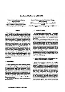
The component presents a set of RFID readers as different reader channels to its clients. When a first client requests access a specific reader, it has to open that channel specifying further parameters like reader gain or transponder subtype, and the opening operation returns the actually used parameters. If another client concurrently requests access to the same reader, it will not be allowed to change the settings, but is able to detect this situation by checking the returned values against its desired parameters. It may then continue with the current settings or decide to abandon its request. While a reader channel is open, the reader hardware periodically starts an RF identification query, and each client can request a set of currently detectable transponders. When the last client closes its reader channel, the actual reader hardware is disabled, i.e. the radio frequency circuits are shut down. A test client application has been implemented to demonstrate the feasibility of the approach. This test uses the software framework to connect to the RFID reader component and to a speech output component. Its local database of transponder IDs and corresponding object description strings allows to tell its audience about the currently detected objects as well as appearing or vanishing objects.
Client1
Client2
RfidComponent
RfidReader
open(config1)
ref
open: config1
create(config1)
RfidChannel init(config1)
request() request: no_tags
detect() set(tags1) open(config2)
detect()
ref
open: config1
detect: tags1
set(tags2)
request()
detect: tags2 detect()
request: tags2
set(tags3) request()
detect()
request: tags3 close()
set(tags4)
detect: tags4 detect()
unref set(tags5) close()
detect: tags3
unref
detect: tags5 detect()
kill()
detect: tags6 shutdown()
kill
Fig. 10 Sequence diagram of multiple clients concurrently accessing an RFID reader
224
T. K¨ampke, B. Kluge, and M. Strobel
Finally, it should be noted that in contrast to other object recognition approaches, an RF identification query will result in unique object instances (e.g. “object no. 1243”), whereas for example a vision based object query will return the classes of the detected objects (e.g. the class “cup”). Therefore, in a component based object recognition framework, an RFID subsystem cannot implement the same software interface as for example a computer vision component.
4 Conclusion The RFID installation onboard the DESIRE platform allowed to detect up to 15 tagged objects in one scene. In order to not disturb the human perception of the objects, tags not exceeding credit card size were used only. Reading ranges onboard the platform were about 120cm which is slightly less than in corresponding lab tests. Estimating distances between the robot and tagged objects by adjusting the reading power proved to be delicate. Anyway, besides mere object identification, disambiguation between tagged objects of identical appearance becomes feasible. The application of RFID technology for service robots operating in everydayenvironments can be expected to go further. Tags attached to furniture, proposed some time ago [11], are becoming standard today. These tags carry inventory information such as a piece of furniture being a ”desk” or ”stove” and the materials of which it is built. It is easy to upgrade this information to include geometric coordinates and handling information for service robots like ”object deposition on surface allowed” and ”deposition of hot objects forbidden” .
References 1. Arumugam, D.D., Engels, D.W.: Characterisation of RF propagation in metal pipes for passive RFID systems. Int. J. Radio Frequency Identification Technology and Applications 1, 303–343 (2007) 2. Deyle, T., Nguyen, H., Reynolds, M.S., Kemp, C.C.: RFID-guided robots for pervasive automation. Pervasive Computing 9, 37–45 (2010) 3. Diana, C.W., Friedman, D.C.W., et al.: Automated tool handling for the trauma pod surgical robot. In: Proc. IEEE International Conference on Robotics and Automation ICRA, Rome, pp. 1936–1941 (2007) 4. Germa, T., Lerasle, F., Ouadah, N., Cadenat, V., Devy, M.: Vision and RFID-based person tracking in crowds from a mobile robot. In: Proc. EEE/RSJ International Conference on Intelligent Robots and Systems IROS, St. Louis, pp. 5591–5596 (2009) 5. Kim, J.-H., et al.: Ubiquitous robot: a new paradigm for integrated services. In: Proc. IEEE International Conference on Robotics and Automation ICRA, Rome (2007) 6. K¨ampke, T., Kluge, B., Prassler, E., Strobel, M.: Robot position estimation on a RFIDtagged smart floor. Springer Tracts in Advanced Robotics 42, 201–211 (2008) 7. Landt, J.: The history of RFID. IEEE Potentials 24, 8–11 (2005) 8. Nemmaluri, A., Corner, M.D., Shenoy, P.: Sherlock: automatically locating objects for humans. In: Proc. MobiSys, Breckenridge, pp. 187–198 (2008)
Exploiting RFID Capabilities Onboard a Service Robot Platform
225
9. Nikitin, P.V., Rao, K.V.S.: Performance limitations of passive UHF RFID systems. In: Proc. IEEE International Symposium on Antennas and Propagation, Albuquerque, pp. 1011–1014 (2006) 10. Olwal, A., Wilson, A.: SurfaceFusion: unobtrusive tracking of everyday objects in tangible user interfaces. In: Proc. 34th Canadian Graphics Interface Conference, Windsor, pp. 235–242 (2008) 11. Omojola, O., et al.: An installation of interactive furniture. IBM Systems Journal 39, 861–879 (2000) 12. Rashid, J.: Towards the development of an ubiquitous networked robot systems for ambient assisted living. In: Proc. IEEE International Conference on Sensor Networks, Ubiquitous, and Trustworthy Computing, Newport Beach, pp. 359–366 (2010)