a nodding 3D scanner with the stop-scan-plan-go operation mode [14] and a ... Surprisingly, the Watchman problem, i.e., a single mobile guard that .... We set up a basic simulation framework to simulate the constantly rotating scanner and the ...
Exploration Strategies for a Robot with a Continously Rotating 3D Scanner Elena Digor, Andreas Birk, and Andreas N¨ uchter Jacobs University Bremen gGmbH, School of Engineering and Science, Campus Ring 1, 28759 Bremen, Germany {e.digor|a.birk|a.nuechter}@jacobs-university.de Abstract. To benchmark the efficiency of exploration strategies one has to use robot simulators. In an exploration task, the robot faces an unknown environment. Of course one could test the algorithm in different real-world scenarios, but a competitive strategy must have good performance in any environment that can be systematically constructed inside a simulator. This paper presents an evaluation of exploration strategies we developed for a specific sensor. A continously rotating 3D laser scanner that scans only into one direction at a time moves through the environment sampling the surrounding. Our evaluation framework features an efficient scanning and robot simulator for kinematic feasible trajectories. We will show that shorter trajectories do not necessarily imply quicker exploration. A simple simulator framework is sufficient for evaluating these properties of path planning algorithms.
1
Introduction
In the last decade, the path planning problems of autonomous mobile robots have received a lot of attention in the communities of robotics, computational geometry, and on-line algorithms. Online exploration is still a crucial issue in mobile robotics. Given an unknown environment, a robot has to find a tour, from which it can eventually see the whole environment. Autonomous robots that can solve the simultaneous localization and mapping (SLAM) problem, need an exploration strategy to operate with true autonomy [10, 16]. However, most of the related problems in computational geometry are NP-hard and it is challenging to program good strategies in a robot control architecture. For example, using a point-like mobile robot model in a polygonal environment and a vision system that is able to see with a 360 degree field of view with infinity range, Hoffmann et al. have presented a strategy yielding a competitive factor of 26.5 [6]. The competitive ratio is the cost of exploration in relation to the optimal exploration with full information. This implies that in the worst case the path of the robot is at most 26.5 longer than the optimal path. Other related theoretical grounded strategies consider the problem of how to look around the corner [3, 4] or optimal search [5]. Despite these impressive theoretical results, real robots face practical problems. Reliable sensors systems are still in the development, real-world environ-
2
ments are not (simple) polygons, and often a decent approximative solution is already considered a good robot behavior. This paper addresses the specific problem of finding a good exploration strategy for a mobile robot with a continuously rotating 3D scanner. Fig. 1 shows such a robot. The main sensor is a RIEGL VZ-400 laser scanner [11] that continuously rotates around the vertical axis and is therfore able to acquire 3D scans while moving. In earlier work, we constructed the mobile robot Kurt3D with a nodding 3D scanner with the stop-scan-plan-go operation mode [14] and a Kurt3D version with a continuously rotating SICK scanner [1]. These robots are regularly used as rescue robots, e.g., in RoboCup rescue, as inspection robots, e.g., for mapping abandoned underground mines, or as surveying system, e.g., for factory design, facility management urban and regional planning. In this paper we develop a simulation-based evaluation framework that allows us to quickly benchmark different strategies while considering kinematic motion constraints.
Fig. 1. The mobile robot Irma3D (Intelligent robot for mapping applications in 3D) with its main sensor, the RIEGL VZ-400.
2
Related Work
Most known approaches use a stop-scan-plan-go method. This problem is an extension of Art Gallery problem [15] : Determine how many guards are sufficient to see every point in the interior of an n-wall art gallery room. The room is assumed to be represented by a simple polygon, i.e., the room can be fully covered by one boundary, which does not cross over itself. The position of the guards can be seen as the points in which the autonomous robot should stop and scan the environment. Lee and Lin [12] proved that the solution to the original Art Gallery problem is NP-hard. Surprisingly, the Watchman problem, i.e., a single mobile guard that moves through the gallery and has to completely see it, can be solved in polynomial time. Unfortunately, robotic exploration is harder. The robot does not know the environment beforehand, so it cannot predict the shape of the environment, and hence any paths it plans cannot be assured to be
3
optimal. Its laser range scanner covers a finite area, in discrete angles and with a maximal distance. A brute force solution to exploring the whole region is to follow the walls and to avoid obstacles. Yamauchi et al. [18] proposed an improved solution for 2D maps, by suggesting to approach the frontiers, i.e. the border between unknown and known regions. The map is usually saved in an evidence grid format, that is a 2 dimensional regular grid, in which a cell contains evidence or probability, based on accumulated sensor readings, that the particular patch of space is occupied. Frontiers are considered to be the cells for which the occupancy probability is equal to a prior probability. The path planning is, then, based on depth first search for finding the frontier regions and for avoiding the obstacles. The robot moves next to a frontier region to take the next scan and to update the evidence grid. We say the environment has been fully explored when the evidence grid has no more frontier regions which are big enough for the robot to go through. A very close solution to Yamauchi, but in 3D this time, is given by Nagatani et al. [13]. Since keeping 3D point clouds is very expensive, the data is preprocessed and it is saved in Multi Level Surface (MLS) map. An MLS map is a 2D grid map, where each cell keeps information about height of objects seen there. Recently, Holz et al. have evaluated [7] exploration strategies. According to their findings, frontier based approaches are sufficiently good in real application scenarios.
3
Exploration Strategies
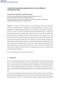
Our exploration strategies are based on frontiers in a 2D grid representation of the environment and extend the flood fill algorithm. Flood fill is often used in image processing applications. The original algorithm colors recursively all the pixels, that neighbor a starting pixel, and that have the same color as it. A neighbor pixel is considered to be the pixel which is up/down/left or right next to the current pixel. An extension of the algorithm’s neighbor definitions, allows us to use it in finding a shortest path to a desired point on the map, in our case, to a frontier point. Since our robot is also allowed to go diagonally at a higher cost, we integrate that part in our exploration model. The classical flood fill algorithm uses depth first search to find and color the neighbors. This is unsuitable for path planning and thus the more efficient Breadth First Filling (BFF) is used. We calculate the radius, i.e., the length of the path from the starting point to the current point, at every step and enqueue the encountered points in a priority queue, instead of an ordinary one, yielding a Breadth First Filling with Priority Queue (BFFPQ) algorithm. The priority queue allows us to sort the points based on their total distance value. Since the map √ resolution is 1 grid cell = 1 cm, a diagonal move is taken to be equal to 2 ≈ 1.44 cm at sub grid cell accuracy. For every grid cell we keep record of the shortest distance from the source (cf. Fig. 2). We implemented the priority queue using a heap. The sort is according to the distance of the inserted points from the source. Hence, an insert and removal from the priority queue has complexity
4 28 24 28 14 0 10
14 24 0 10 20
14 24 0 10 20
28 24 28 14 24 0 10 20
38 34 38 28 24 28 38
38 34 38 28 24 28 38
14 24 34 0 10 20 30
14 24 34 0 10 20 30
Fig. 2. Breadth first filling with priority queue. The grid cells that have been processed are shown in red, the cells in the queue are shown in yellow and the distances (in mm) from the source to the corresponding cell are given in digits.
O(logN ) in worst case scenario. In practice this algorithm runs faster, due to the fact that the sorting operations are on top of the list. The BFFPQ algorithm guarantees to find out the closest frontier. However, we are also interested in the actual path that the robot has to follow to reach that frontier. For finding it we run a backward search algorithm that calculates the path from the frontier point, step by step back to the source. Next, we describe four strategies to explore the whole environment. Their basis is BFFPQ for automatic exploration missions. 3.1
Stop-scan-replanning-go strategy
The Stop-scan-replanning-go strategy starts with a 360◦ scan, and then runs BFFPQ and finds the first frontier grid cell. After finding the path to this cell, the robot follows it to reach the goal. Once it reaches the goal, it stops, and does a 360◦ scan. Next, as the name of the algorithm suggests, the robot re-plans its new goal by finding the closest frontier and the path towards it. The algorithm continues this way until the robot has no more reachable frontiers. In this strategy the 3D scanner is constantly rotating, i.e., also during the path following. 3.2
Scan-replanning-go strategy
A second algorithm is a small deviation from the previous one. Instead of doing constant stops for a full scan of the environment, we instantly compute a new frontier cell to reach. The incentive is to save the time required for stopping and scanning in favor of a shorter overall total time for an entire map exploration. 3.3
Continuously-replanning-with-stopping strategy
The following strategy takes full advantage of the fact that while moving the robot also scans the environment, which in most of the cases might result in opening the goal-frontier, before actually reaching it. Hence, we implemented an algorithm according to which, once the robot opens the frontier point while following a path towards it, the robot instantly searches for another goal point and changes its path towards the new one. Recall that whenever the robot aims to reach a frontier, it tries to reach the closest one. Hence, if the robot opens it before actually reaching it, there is a
5
very small chance that a full 360◦ scan would actually lead to new discoveries on the map. Hence, we do not stop the robot, but make the robot go instantly to the next closest frontier. Reaching the goal point however, implies that the rotating scanner failed to explore the frontier pixel while being on the way towards it. As a result, it seems that most probably the robot is located in a quiet unexplored area, and it would be advantageous for it to stop and do a full 360◦ scan. 3.4
Continuously-replanning strategy
The Continuously-replanning strategy is a modification of the latter one, with the constraint that the robot never stops. Similarly to the scan-replanning-go strategy we aim at saving overall exploration time. The robot starts with a 360◦ scan, and afterwards it finds the closest frontier to go to. It follows the path towards it, and if while moving towards the goal the robot explores the frontier, it sets a new goal and a new path to follow. Again, this exploration is complete when there are no more frontiers on the map that the robot can reach.
4
Scanner and Robot Simulation
We set up a basic simulation framework to simulate the constantly rotating scanner and the mobile robot. 4.1
The Scanner
Scanning is an essential part of our exploration missions. However, since simulator is currently in 2D we have to simulate 72 scans per second to yield a scan resolution of 1◦ . Hence a full 360◦ scan takes 5 seconds, which corresponds to our used hardware the Riegl VZ-400. By having the length of a beam, we can easily calculate a far-most point (in our coordinate system) for each scan line. Hence, at every time step, the simulator has to mark all grid cells starting with the current robot position (x, y) and ending either with far-most point or at the closest encountered obstacle. We use the Bresenham algorithm to quickly simulate the beams [2]. Beam divergence does not have to be considered, since it is negligible for the VZ-400. However, the used Bresenham algorithm has to be altered, if other laser scanners are simulated. For example the laser spot projected by the SICK LMS-200 is already at a distances of 5 meter roughly 4 cm and therefore considerable high. Frontier computation. Since our exploration algorithms are all based on closest frontier method [18], at any point in time the exploration algorithm has to record the current frontiers. A frontier is defined as all unexplored grid cells which directly border with already explored free cells. The frontier pixels are marked on the robot’s generated map. Hence, the frontier regions are continuously marked with every beam that the laser scanner emits (cf. Fig. 3).
6
Fig. 3. Left: A single laser line (white cells) generation via Bresenham algorithm, with frontier markings (green cells) at every construction step (from left to right). Right: A simulated scan in a room. Due to the rotational resolution not all walls are completely sampled.
4.2
The Robot Platform
The robot is the main component being simulated. Irma3D is a differential drive robot. Besides a manual control, we simulate the kinematics of the differential drive vehicle on the set velocities vl and vr for the left and right wheel on a common axis at a distance 2b one from the other. Let u e1 and ω e2 be the linear and angular velocities of the mid point of such axis being e1 and e2 body fixed unit vectors as depicted in Fig. 4. Let e1 vr and vl e1 be the velocities of the center of the right and left wheels that are assumed to roll perfectly. The kinematic model linking the scalars u, ω, vr and vl is: u=
1 (vr + vl ) 2
ω=
1 (vr − vl ) 2b
(1)
where |vr | and |vl | will be bounded by some given value Vm . As known, a differential drive vehicle modeled by equations (1) can move on paths of arbitrary curvature κ, as κ=
1 vr − vl . b vr + vl
(2)
Fig. 4. Left: Differential drive. Right: The used Frenet frame.
Indeed for any vl = −vr the corresponding path curvature would be infinite, i.e. the vehicle would turn on the spot. Arbitrarily large curvature values can be implemented if the wheels rotate in opposite directions. Yet if the vehicle should be required to move nicely and possibly at high linear speeds, commanding
7
wheel speeds of different sign in order to make sharp turns should be avoided in practice in order not to overstress the electromechanical structures of the robot, e.g. gear boxes, tires, DC motor H-Bridge power circuits. If the wheel speeds vl and vr should be constrained to positive values only, than the curvature κ given by equation (2) would be bounded � � 1 1 if vl , vr ∈ [0, Vm ] (3) κ∈ − , b b and the linear speed u > 0 should be constrained to u ≤ Vm /2 to let κ span its full range [−1/b, 1/b] [8]. Our simulation environment considers the path following controller designed in [17]: given a Serret-Frenet frame {F } moving along the planar path, call P its origin having curvilinear abscissa s with respect to an arbitrary path point (origin of the curvilinear abscissa). Call {I} a fixed inertial frame and Q the mid point of the differential drive robot axis such that Q has coordinates (s1 , y1 ) in {F } and (x, y) in {I} (cf. Fig. 4, right). Calling κr the curvature of the reference path, the kinematics of Q in {I} would be given by the unicycle model x˙ =u cos θm
y˙ = u sin θm
θ˙m = ω
(4)
and by s˙ 1 = − s˙ (1 − κr y1 ) + u cos θ
(5)
y˙ 1 = − κr s˙ s1 + u sin θ θ˙ =ω − κr s˙
(6) (7)
in {F } (refer to [17] for details) being θm and θ the vehicle’s heading in {I} and {F } respectively. Following [17] we consider the Lyapunov candidate function V1 =
� 1 1 2 2 s1 + y12 + (θ − δ(y1 , u)) 2 2γ
(8)
for some positive γ to derive the closed loop, time invariant and globally stable control law: sin θ − sin δ θ˙ = δ˙ − γ y1 u − k2 (θ − δ) θ−δ s˙ = u cos θ + k1 s1 with k1 > 0, k2 > 0
(10)
The above control law yields the commanded wheel velocities as � � � � vr = u + b κr s˙ + θ˙ vl = u − b κr s˙ + θ˙
(11)
(9)
in which the maximal set values can be incorporated [9], preserving the property of a closed loop, time invariant and globally stable controller.
8
5
Experiments and Results
The performance of our developed algorithms was analyzed on our testing bench, the simulator. The testing was based on 5 different maps, which are presented in Fig. 5. For each of the five maps we created 10 different random starting states for the robot. All four algorithms were applied to each testing case.
Fig. 5. Five maps used for evaluation: Simple map, empty office map, office map with obstacles, campus roads and campus buildings. Bottom right most map is a satellite view of the campus
Fig. 6 shows the resulting trajectories of 4 algorithms on the simple map. We notice that in all the cases where the exploration algorithm implied no full stop for a 360◦ scan, i.e. Scan-replanning-go strategy, and Continuously-replanninggo strategy, the path comes out to be longer and jittery. In Fig. 6 (second), one can see that the robot, even has a tendency to go in a circular trajectory. This behavior is due to the fact that the robot does not stop, and it’s doing planning and scanning while moving. Hence, it might be the case, that while reaching a goal point on the map, the environment around is still barely explored. A full scan is done in 5 seconds, which means every time step the robot does a move, it covers only 72◦ of the environment. Similar results have been obtained in the other maps, see Fig. 7 and Fig. 8. Exploration path lengths for all strategies are given in Fig. 9 and the corresponding exploration time in Fig. 10. Please notice the scaling of the y-axis. An additional observation is that once the office map contains clutter, i.e., obstacles, the total path length increases significantly for the non-stopping algorithms. The reason is that the obstacles, being of different geometrical forms, block the laser
Fig. 6. Results in the simple map. From left to right: Stop-scan-replanning-go, Scanreplanning-go, Continuously-replanning-with-stopping, and Continuously-replanninggo strategy.
9
Fig. 7. Results in the office map with clutter. From left to right: Stop-scan-replanninggo, Scan-replanning-go, Continuously-replanning-with-stopping, and Continuouslyreplanning-go strategy.
Fig. 8. Results in the large outdoor map. From left to right: Stop-scan-replanninggo, Scan-replanning-go, Continuously-replanning-with-stopping, and Continuouslyreplanning-go strategy.
beams from reaching the entire room, and as a consequence the robot has to wander around more, before it explores one entire room.
10 Average path length for ’Simple map’
Average path length for ’Office Map’
Average path length for ’Office map with obstacle 3500
500 400 300 200 100 0 Alg0
Alg1
Total path length [cm]
3500 Total path length [cm]
Total path length [cm]
600
3000 2500 2000 1500 1000 500 0 Alg0
Alg2 Alg3 Joystick Algorithm #
Alg1
Average path length for ’Campus roads’ Total path length [cm]
Total path length [cm]
5000 4000 3000 2000 1000 0 Alg0
Alg1
Alg2
2500 2000 1500 1000 500 0 Alg0
Alg2 Alg3 Algorithm #
7000 6000
3000
Alg3
Alg1
Alg2 Alg3 Algorithm #
Average path length for ’Campus Buildings’ 8000 7000 6000 5000 4000 3000 2000 1000 0 Alg0 Alg1 Alg2 Alg3
Algorithm #
Algorithm #
Fig. 9. Average and deviation of the path lengths for the four exploration strategies in our five maps. From top left to bottom right: Simple map, empty office map, office map with obstacles, campus roads and campus buildings. The visualization for the simple map contains in addition the path length for exploration by an operator. Average path length for ’Simple map’
Average time steps for ’Office Map’
6000 4000 2000 Alg1
Alg2
Total time [time steps]
8000
0 Alg0
Average time steps for ’Office map with obstacle 30000
30000 Total time [time steps]
Total time [time steps]
10000
25000 20000 15000 10000 5000 0 Alg0
Alg3 Joystick
Alg1
Algorithm #
Alg2
20000 15000 10000 5000 0 Alg0
Alg3
Alg1
Algorithm # Average time steps for ’Campus Roads’
50000 40000 30000 20000 10000 0 Alg0
Alg1
Alg2 Algorithm #
Alg3
Alg2
Alg3
Algorithm # Average time steps for ’Campus Buildings’
Total time [time steps]
Total time [time steps]
25000
60000 50000 40000 30000 20000 10000 0 Alg0
Alg1
Alg2
Alg3
Algorithm #
Fig. 10. Average and deviation of exploration times for the four strategies in our five maps. From top left to bottom right: Simple map, empty office map, office map with obstacles, campus roads and campus buildings. The visualization for the simple maps contains in addition the time needed for exploration by an operator.
The large scale maps (Fig. 5 bottom) emphasize our observation that in all the cases where the exploration algorithm implies no full stop for a 360◦ scan, i.e. Scan-replanning-go strategy, and Continuously-replanning-go strategy, the path comes out to be very long and jittery. On the other hand, the overall time for the exploration was much shorter than for the other two algorithms. Moreover Stop-scan-replanning-go and Continuously-replanning with stopping strategies seem to do similarly good in total path length, but the latter one seems to have an advantage in the total time spent for the entire exploration. Furthermore, for the large maps, we see a considerable gap between the total path length of the strategies with stopping compared to the ones without. Since both of the maps appear relatively uniform, and very big, statistically speaking,
11
there are no more favored starting positions. Any position the robot will start from will cover a very small portion of the map, and every stop cleans up a small circle area. Hence the robot will more or less go through many small areas, A video of the exploration strategies can be found under the following links: http://plum.eecs.jacobs-university.de/download/simpar2010.mpg and http://plum.eecs.jacobs-university.de/download/simpar2010 cmp.mpg
An additional finding is that the paths, that have been computed by the planner, were most of the time feasible by the closed loop, time invariant and globally stable control law with bounded wheel velocities. However, sometimes the robot control has to revert to a much simpler path following strategy, where the robot is allowed to turn on the spot.
6
Conclusion and Future Work
Exploration is an ongoing research area in robotics. The emerging technology of 3D sensing devices results in additional challenges exploration algorithms must handle. Most of the literature cover the theoretical analysis of different stop and scan methods with a scanner that has a fixed field of view and which is attached on the top of the robot. Our aim was to take usage of a constantly rotating 3D scanner, and to consider its advantages by using scanning on the fly methods. We developed and tested in simulation four different exploration strategies which are based on the frontier approach combined with an extension of flood fill algorithm. Two of the algorithms involve stopping at frontier points to take full 360◦ scans of the environment, and the other two implied constant movement until the entire map is covered. In order to test the soundness and consistency of our exploration methods, we have implemented our own small simulator. The robot is simulated by a differential drive model, with a constantly rotating scanner attached to it. The scanner does a full 360◦ scan of the environment in a certain time, and updates the map accordingly. Furthermore, the proposed small simulator enables us to test kinematic robot control laws, such as the presented de Wit’s control. This enables us to quickly determine control parameters, without using real hardware. This paper has shown that for certain problems there is no need for a sophisticated simulation environment. A home-brew small simulator enables the roboticist to study important issues of a real robotic system. In future work, we will test the proposed exploration strategies in combination with the closed-loop path following on the real robot Irma3D. All application scenarios that require 3D robotic mapping benefit from the proposed study. In addition, we’ll work on the theoretical foundations of the exploration method and aim at finding the competitve ratio of exploration with a continously rotating sensor.
12
References 1. C. Brenneke, O. Wulf, and B. A. Wagner. Using 3D laser range data for SLAM in outdoor environments. In Proceedings of the IEEE/RSJ International Conference on Intelligent Robots and Systems (IROS ’03), Las Vegas, USA, October 2003. 2. J. E. Bresenham. Algorithm for computer control of a digital plotter. IBM Systems Journal 4, 4(1):25–30, 1965. 3. S. P. Fekete, R. Klein, and A. N¨ uchter. Online searching with an autonomous robot. Computational Geometry: Theory and Applications (CGTA), 34(2):102–115, 2006. 4. S. P. Fekete and C. Schmidt. Polygon exploration with time-discrete vision. Computational Geometry: Theory and Applications (CGTA), 43:148–168, 2010. 5. R. Fleischer, T. Kamphans, R. Klein, E. Langetepe, and G. Trippen. Competitive online approximation of the optimal search ratio. In Proc. of the 12th Annual European Symp. on Algorithms (ESA ’04), pages 335–346, Bergen, Norway, 2002. 6. F. Hoffmann, C.Icking, R.Klein, and K.Kriegel. The polygon exploration problem. SIAM Journal on Computing (SICOMP), 31:577 – 600, 2001. 7. D. Holz, N. Basilico, F. Amigoni, and S. Behnke. Evaluating the efficiency of frontier-based exploration strategies. In Proceedings of the joint conference of the 41st International Symposium on Robotics (ISR 2010) and the 6th German Conference on Robotics (ROBOTIK 2010), Munich, Germany, 2010. 8. G. Indiveri and M. L. Corradini. Switching linear path following for bounded curvature car-like vehicles. In Proceedings of the IFAC Symposium on Intelligent Autonomous Vehicles (IAV ’04), Lisbon, Portugal, July 2004. 9. G. Indiveri, A. N¨ uchter, and Kai Lingemann. High speed differential drive mobile robot path following control with bounded wheel speed commands. In Pro. of the IEEE Intl. on Conf. Robotics and Automation (ICRA ’07), Rome, Italy, 2007. 10. S. K¨ onig, C. Tovey, and W. Halliburton. Greedy mapping of terrain. In Proceedings of the IEEE International Conference on Robotics and Automation (ICRA ’01), pages 3594–3599, Seoul, Korea, May 2001. 11. Riegl Laserscanner. http://www.riegl.co.at/, 2010. 12. D. Lee and A. Lin. Computational complexity of art gallery problems. Information Theory, IEEE Transactions on, 32(2):276–282, Mar 1986. 13. Keiji Nagatani, Takayuki Matsuzawa, and Kazuya Yoshida. Scan-point planning and 3-d map building for a 3-d laser range scanner in an outdoor environment. In Field and Service Robotics (FSR ’09), volume 62 of Springer Tracts in Advanced Robotics, pages 207–217, 2010. 14. A. N¨ uchter, H. Surmann, and J. Hertzberg. Planning robot motion for 3D digitalization of indoor environments. In Proceedings of the 11th International Conference on Advanced Robotics (ICAR ’03), pages 222–227, Coimbra, Portugal, June 2003. 15. Joseph O’Rourke. Art Gallery Theorems and Algorithms. Oxford University Press, New York, NY, 1987. 16. D. Pierce and B. Kuipers. Learning to explore and build maps. In Proceedings of the twelfth national Conference on Artificial Intelligence (AAAI ’94), pages 1264– 1271, Seattle, W.A., U.S.A., July 1994. 17. D. Soetanto, L. Lapierre, and A. Pascoal. Adaptive, Non-Singular Path-Following Control of Dynamic Wheeled Robots. In Proceedings of the 42nd IEEE Conference on Decision and Control (CDC ’03), pages 1765–1770, Maui, Hawaii U.S.A., December 2003. 18. B. Yamauchi. A frontier-based approach for autonomous exploration. In Proc. IEEE Intl. Symp. on Computational Intelligence in Robotics and Automation (CIRA ’97), pages 146–151, 1997.