[1] Andrew Adams, EinoVille Talvala, Sung Hee Park, David E. Jacobs, Boris. Ajdin, Natasha Gelfand, Jennifer Dolson, Daniel Vaquero, Jongmin Baek, Mar.
EXPLORING ABSTRACT INTERFACES IN SYSTEM-ON-CHIP
INTEGRATION
A DISSERTATION
SUBMITTED TO THE DEPARTMENT OF ELECTRICAL
ENGINEERING
AND THE COMMITTEE ON GRADUATE STUDIES
OF STANFORD UNIVERSITY
IN PARTIAL FULFILLMENT OF THE REQUIREMENTS
FOR THE DEGREE OF
DOCTOR OF PHILOSOPHY
Andrew Danowitz
July 2014
© 2014 by Andrew Robert Danowitz. All Rights Reserved. Re-distributed by Stanford University under license with the author.
This work is licensed under a Creative Commons AttributionNoncommercial 3.0 United States License. http://creativecommons.org/licenses/by-nc/3.0/us/
This dissertation is online at: http://purl.stanford.edu/tx933ws5747
ii
I certify that I have read this dissertation and that, in my opinion, it is fully adequate in scope and quality as a dissertation for the degree of Doctor of Philosophy. Mark Horowitz, Primary Adviser
I certify that I have read this dissertation and that, in my opinion, it is fully adequate in scope and quality as a dissertation for the degree of Doctor of Philosophy. Christos Kozyrakis
I certify that I have read this dissertation and that, in my opinion, it is fully adequate in scope and quality as a dissertation for the degree of Doctor of Philosophy. Stephen Richardson
Approved for the Stanford University Committee on Graduate Studies. Patricia J. Gumport, Vice Provost for Graduate Education
This signature page was generated electronically upon submission of this dissertation in electronic format. An original signed hard copy of the signature page is on file in University Archives.
iii
Abstract
Modern mobile devices are marvels of computation. They can encode highdefnition video, processing and compressing over 350MB/s of image data in real time. They have no trouble driving displays with as much resolution as a full laptop, and smart phone manufacturers boast of running games with "console quality" graphics. Mobile devices pack all of this computational power into a 12\ handheld package by inte grating a number of specialized hardware accelerators (IP) along with conventional CPU and GPUs in a systemonchip (SoC). Unfortunately, creating these specialized systems is becoming increasingly expen sive. Since hardware accelerators come from a number of diferent sources and design cycles, diferent accelerator blocks will often contain incompatible hardware inter faces. Therefore, a large portion of SoC design cost comes in the form of designers manually interfacing each accelerator into a system. This work includes everything from building custom logic to wire up a block, to developing the drivers and API needed to take advantage of the hardware. My research focuses on generating these interfaces, including the physical hard ware used to tie IP blocks into a system and the associated software collateral. Lever aging recent trends such as High Level Synthesis and other hardware "generator" methodologies, I propose an IP interface abstraction and parameterization designed to describe the interface of most current IP blocks. By encoding this knowledge at a higherlevel of abstraction, I am able to construct and demonstrate a hardware gen erator that maps an interface protocol description into synthesizable register transfer language (RTL), and that can automatically create hardware bridges between difer ent interconnect standards.
iv
To ease the integration of the next generation of IP blocks-blocks that are au tomatically generated based of of user specifcation-I propose a set of interface primitives. \hen integrated into an IP generator, these primitives can automatically generate an interface that my interface system can tie to the rest of the system. I also demonstrate how the information stored in these types of primitives can be used to automatically generate a lowlevel software driver that manages access to the IP blocks. Finally, I show how the simulation environment provided with an IP generator can be used to provide a domain appropriate application programming interface (API) to drive the software. Using an image signal processor generator as my platform, I demonstrate the construction of a map between the simulation software and hardware driver that enables a full onebutton fow from algorithm development to applications running on specialized hardware within a working system.
v
Acknowledgments I dedicate this thesis to my family and friends whose love and support helped me through graduate school. I would also like to thank my advisor, Mark Horowitz for his guidance, insight, and patience, and my mentors, Ofer Shacham and Stephen Richardson.
vi
Contents Abstract
iv
Acknowledgments
vi
1 Introduction
1
1.1
Hitting a Power \all: The Continued Case for Custom Design . . . .
3
1.2
Automating SoC Integration . . . . . . . . . . . . . . . . . . . . . . .
6
2 Previous Work in Interface Generation
10
3 Interface Abstraction
16
. . . . . . . . . . . . . . . . . . . . . . . .
17
3.1
Defning a Basic Interface
3.2
Creating an Interface Description
. . . . . . . . . . . . . . . . . . . .
18
3.3
Handling Interface Complexity . . . . . . . . . . . . . . . . . . . . . .
22
3.4
Mapping Real Interfaces
. . . . . . . . . . . . . . . . . . . . . . . . .
23
3.5
Generating Interface Bridges . . . . . . . . . . . . . . . . . . . . . . .
30
3.6
Validating the Abstraction . . . . . . . . . . . . . . . . . . . . . . . .
34
3.7
Extending the Generator . . . . . . . . . . . . . . . . . . . . . . . . .
35
3.8
Summary
37
. . . . . . . . . . . . . . . . . . . . . . . . . . . . . . . . .
4 Advertising Native Interfaces
38
4.1
Image Signal Processor Generator . . . . . . . . . . . . . . . . . . . .
40
4.2
Mapping HLS to RTL
. . . . . . . . . . . . . . . . . . . . . . . . . .
42
Specifying Flow Control and Access . . . . . . . . . . . . . . .
45
4.2.1
vii
4.3
Building an HLStoRTL System
. . . . . . . . . . . . . . . . . . . .
48
4.4
Interconnect Generator . . . . . . . . . . . . . . . . . . . . . . . . . .
51
4.5
Testing and Summary
54
. . . . . . . . . . . . . . . . . . . . . . . . . .
5 Automating Software Generation 5.1
5.2
56
Building Drivers . . . . . . . . . . . . . . . . . . . . . . . . . . . . . .
57
5.1.1
Driver Design Techniques
. . . . . . . . . . . . . . . . . . . .
58
5.1.2
Generating the Driver
. . . . . . . . . . . . . . . . . . . . . .
61
Generating the API . . . . . . . . . . . . . . . . . . . . . . . . . . . .
66
5.2.1
Mapping the API to the Driver
. . . . . . . . . . . . . . . . .
68
5.2.2
API Limitations and Future \ork . . . . . . . . . . . . . . . .
69
5.2.3
API Summary . . . . . . . . . . . . . . . . . . . . . . . . . . .
70
6 Conclusions
71
Bibliography
74
viii
List of Tables 2.1
Signal and encoding diferences between AXI3 and AXI4. . . . . . . .
11
3.1
Parameters required to encode the basic IP interface.
. . . . . . . . .
19
3.2
Parameters required to encode the basic bus. . . . . . . . . . . . . . .
24
3.3
Parameter Mappings for the system buses.
. . . . . . . . . . . . . . .
27
3.4
Keywords used to map interface functionality to specifc signal names.
28
4.1
Summary of my Genesis 2 interface primitives. . . . . . . . . . . . . .
45
4.2
Summary of fow control details primitives pass to HLS. . . . . . . . .
49
4.3
Sufxes for constructing diferent control signal names.
. . . . . . . .
50
5.1
Summary of IP interface information provided by each primitive. . . .
63
ix
List of Figures 1.1
Die photo and block diagram of NVidia Tegra K1 processor [23]. . . .
2
1.2
Annotated die photo of Intel "Haswell" processor [27]. . . . . . . . . .
3
1.3
Frequency scaling of processor designs over time [14].
. . . . . . . . .
4
1.4
Power density of processor designs over time [14].
. . . . . . . . . . .
5
1.5
Voltage versus feature time of historical processors [14]. . . . . . . . .
5
1.6
Energy efciency for algorithms on diferent platforms [33]. . . . . . .
7
3.1
High level fow for the interface generator.
. . . . . . . . . . . . . . .
30
3.2
High level architecture of the prototype bridge generator. . . . . . . .
32
4.1
Block diagram of an RTL IP architecture.
43
4.2
Code to instantiate and confgure
4.3
Code used to map an interface bus in an IP design to a
4.4
Code used to generate Verilog module instantiation from primitives. .
51
4.5
Code used to map an interconnect standard to my primitives.
. . . .
53
4.6
Flow diagram of how my primitives work with Genesis 2.
. . . . . .
55
5.1
Block diagram of my driver generator system.
. . . . . . . . . . . . .
61
5.2
A C struct mapping interface resources to the
x
buffrfd
. . . . . . . . . . . . . . . primitive.
mmap
. . . . . . . . .
buffrfd
structure.
50
primitive. 51
. . . .
65
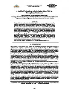
Chapter 1 Introduction As seen in Figure 1.1, SoCs incorporate traditional processor cores as well as a myr iad of custom hardware accelerators.
These accelerators are designed to compute
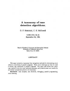
data intensive applications in realtime, like graphics, image processing, and wireless communications, and are optimized to do so in a very energy efcient manner. As a result, they are widely used in the mobile space where packaging and battery life requirements necessitate highly efcient computing solutions. In recent years, the energy and performance benefts of integrating custom hard ware ondie with the processor has led traditional desktop processor manufacturers to start moving towards SoClike designs. Figure 1.2 shows the die of Intel's latest generation "Haswell" desktop processor. \hile the processor cores and cache take up more area here than in mobile SoCs, over a third of the die is dedicated to acceler ators and peripheral controllers, including graphics, memory controllers, and display handlers. The energy benefts of SoCs, however, come with a price.
The complexity of
getting all of these diferent hardware accelerators, or "IP blocks" to work together has caused the engineering costs of developing and verifying an SoC design to skyrocket, and by some estimates, the cost of developing the software to get an SoC system to function now dwarfs the cost of actual hardware development [21]. These factors have meant that the number of new custom chip starts is actually decreasing [20]. To help alleviate these factors, my doctoral work attempts to leverage recent trends in
1
CHAPTER 1.
2
INTRODUCTION
GPU Cores CPUs
Figure 1.1: Die photo (top) and block diagram (bottom) of upcoming NVidia Tegra K1 processor. In addition to processor cores, the chip contains a substantial graphics fabric, video and image processing units, and a range of other peripherals [23].
CHAPTER 1.
INTRODUCTION
3
Figure 1.2: Annotated die photo of Intel "Haswell" (4th Generation Core Architec ture). Less than half of the die area is dedicated to processor cores [27].
highlevel synthesis (HLS), hardware generation, and domain specifc programming languages (DSLs) to help automate the process of IP integration.
1.1 Hitting a Power Wall: The Continued Case for Custom Design \ith the rising costs of chip design, one might expect that custom would be on its way out. The historical growth in the performance of general purpose processors made it seem like many of the applications that used to require custom accelerators could eventually be migrated into software. In practice, however, more and more portions of die area dedicated to custom accelerators and other types of specialized computation engines: since the release of Intel's Sandy Bridge and AMD's Llano architectures in 2011, many mainline desktop parts have started incorporating programmable graph ics engines, among other accelerators directly ondie, providing a huge boost to the mathematical abilities and parallel computing resources of these parts. Also, modern mobile and desktop processing parts like the K1 and Haswell continue to dedicate large portions of die area to custom logic. The reason for the continued success of custom is that most modern processor designs are power limited. As seen in Figure 1.3, the rate of general purpose processor
CHAPTER 1.
4
INTRODUCTION
Figure 1.3: Frequency scaling of processor designs over time [14].
performance growth, as measured by operating frequency, has slowed considerably since 2005.
The reason for this is that designers had been exploiting architectural
techniques that increase performance at the cost of increasing power density [14]. This is shown in Figure 1.4. \hen processor power density reached roughly
1W/mm2
[14]
in 2005, however, designers reached the limit of what could be efciently aircooled. From that point on, architects could no longer trade power for performance, which greatly slowed the rate of performance scaling. To make matters worse, since roughly the 45nm generation, power and perfor mance benefts from technology scaling have declined. According to Dennard's Con stant Field Scaling [15], if all of the physical dimensions and the threshold voltage of a transistor are scaled down by a factor of drops by a factor of factor of
√ 2
α
3
α,
the energy required to switch a transistor
. Historically, this meant that as feature size has dropped by a
with each technology node, designers were able to double the number of
CHAPTER 1.
5
INTRODUCTION
Figure 1.4: Power density of processor designs over time [14].
Vdd
5
3
2
1.5 10
2.37
0.56 Feature Size [um]
0.13
0.03
Figure 1.5: Voltage versus feature size. Voltage scaling, which began at roughly the half micron node, has largely leveled of since the 45nm generation [14]. The trendline is provided to show the sharp cutof in scaling.
CHAPTER 1.
6
INTRODUCTION
transistors, increase the processor's operating frequency, and still maintain a constant power density. Unfortunately, for performance to improve as operating voltage, scaled, the threshold voltage,
Vth ,
Vdd ,
needs to scale as well. Due to leakage power con
cerns, however, threshold voltages are no longer scaling at the same rate as the rest of the transistor, as illustrated in Figure 1.5, and thus
Vdd
scaling has dramatically
slowed as well. Since performance is proportional to operations per second and power is propor tional to the product of energy per operation and performance (P
∝
ops s
×
E ), if op
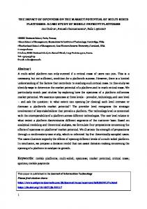
power is fxed, the only way to increase performance is through decreasing energy per operation. This can be accomplished by tailoring hardware to specifcally match the needs of the underlying algorithms. Custom accelerators are designed to do this. By giving up the generality found in general purpose processors and optimizing data paths for a certain class of algorithms, custom accelerators can achieve up 1000 times lower energy than general purpose processors [22], as shown in Figure 1.6. As a result, the SoC design methodology and customization are likely to play an important role in chip design for the foreseeable future.
1.2 Automating SoC Integration In this thesis, I attempt to reduce some of the hardware and software related design costs through automation. My work does this by using the hardware generator design methodology-rather than building a single hardware instance, we build softwarelike constructors to generate customized hardware instances-to automate the integration of IP blocks into an SoC design. Much work has already been done to simplify the process of wiring an IP block into a system on chip, and this work is overviewed in Chapter 2. IP blocks generally adhere to one of many industrystandard interfaces that were designed to aid the problem of integration. Unfortunately, the wide range of interface standards, and backwards compatibility issues between interface revisions mean that an SoC integrator will likely end up using IP blocks with incompatible interface standards. To address this problem, researchers have explored various ways to encode the IP communication
CHAPTER 1.
INTRODUCTION
7
Figure 1.6: Energy efciency for algorithms implemented on diferent platforms [33]. Each mark on the XAxis represents a unique design published in JSSC.
CHAPTER 1.
8
INTRODUCTION
protocol at a higher level, and automatically generate bridge logic.
This chapter
will review these methods, and highlight some improvements that a generatorbased approach can address. Chapter 3 attempts to address the problems of connecting IP with fxed interface standards to each other and to modern highlevel designs by introducing an abstrac tion for IP style interfaces. I identify four key characteristics that must be present in any IP interface and then propose a parameterization of this interface space that is fexible enough to account for the diferences between most IP buses.
Using my
abstraction, I demonstrate a method for automatically generating hardware to bridge between any two supported interfaces. The conversion method I use is based on three steps that handle signal resynchronization, physical resources provisioning, and con trol signal conversion, and is implemented in the Genesis 2 [43] generator language. I verify my generator's functionality by producing and simulating bridges for a number of popular interconnect standards. \hile my interface abstraction works well for existing IP blocks, future SoC de signs are likely to use highlevel design methodologies to help ease the process of IP design and to automate hardware integration. Since designers may still rely on RTL based design methodologies for certain specialized accelerators that don't map well to their highlevel design tools, in Chapter 4, I demonstrate a system for mapping high level interface elements to RTLbased accelerator blocks.
The work discussed here
allows any IP designs that must be specifed through RTL to still take advantage of the systemintegration benefts of highlevel synthesis. Next, to push the capabilities of IP integration into the software domain, Chap ters 4 and 5 discuss my work to introduce transaction level model (TLM) based interfaces into Genesis 2, and to adapt the interface information found in these inter faces to automatically generate a C driver for generated IP blocks. I demonstrate and verify the functionality of my interface primitives and driver generator in the context of an image signal processor (ISP) IP generator (ISPGen) [10]. \ith a mechanism for automatically generating a software driver, Chapter 5 then focuses on how we can automatically generate software APIs for the IP so that do main experts without hardware knowledge can take advantage of the hardware. This
CHAPTER 1.
INTRODUCTION
9
chapter demonstrates a proofofconcept methodology for automatically generating hardware APIs. All IP generators will come with some sort of simulation collateral that allow a system designer to test various parameter options before settling on a fnal fxed IP. Since the same set of generator parameters and design constraints gov ern how the hardware and the software simulator are created, for a given set of IP parameters, it is generally possible to create a mapping between the relevant simula tion interface and the required driver commands to complete the same computation on the hardware. By integrating this technique into the ISP generator, we are able to construct a system that allows for domain experts with little knowledge of computer hardware to experiment with novel image processing algorithms in realtime.
Chapter 2 Previous Work in Interface Generation SoC design methodology is widely used in chip design. It allows users to assemble entire systems out of prebuilt, preverifed IP blocks. These IP blocks can be sourced from both internal and external vendors, so, for example, an SoC might feature a processor design from ARM, and graphics from Imagination. It is the job of the SoC designer to integrate these devices together to form a fully functional system. To help manage the complexity of integrating IP blocks from diferent vendors, most IP blocks adhere to one of a variety of interface standards.
These standards
defne the signals, timing, and handshaking protocols used by the IP blocks to com municate.
Major system designers like IBM [26], Intel [28], and ARM [2], and a
number of consortia like Accelera [36] and Hypertransport [24] all maintain sets of incompatible interconnect standards. Therefore, it is likely that not all of the blocks a system designer plans to use advertise the same interface standard. To make matters worse, standard groups often maintain more than one standard for IP interfaces. The widely used ARM AMBA standard, for example, is actually
1
a family of 10 buses and bus variants .
Each of these buses is designed with a
diferent use case in mind. For example, AXI is used as an interface for generic high performance peripherals. AXIStream, on the other hand, is specifcally designed for
1 APB,
ASB, AHB, AHB-Lite, ATB, AXI, AXI-Stream, AXI-Lite, ACE, ACE-Lite
10
CHAPTER 2.
11
PREVIOUS \ORK IN INTERFACE GENERATION
blocks with streaming interfaces, and APB is used for low performance functions, like control interfaces. These buses are all incompatible, and custom bridge logic is needed to convert between the ARM interfaces. Therefore, even if a particular group's standard dominates a market, like ARM buses in the mobile space, designers may still face the problem of trying to integrate multiple interface standards. Finally, even if blocks conform to the same nominal standard, there is no guaran tee that they can actually communicate with each other. As technology progresses and designers fnd new ways to optimize their interconnects, interface standards are revised.
Often these revisions are not backwards compatible with the version they
replace. For example, in version 3 of the AXI protocol, information sent along the
writf
bus can be reordered independently of the corresponding data sent on the
ad
drfss
bus. To keep track of which data is associated with each address, the address
and data values of a single transaction are assigned a transaction ID. In AXI version 4, however, address and data can no longer be independently reordered, and the IP blocks are designed to assume that any address and data pairs they receive, regardless of timing, correspond to the same bus transaction. Other discrepancies between the two standards are shown in Table 2.1. Because of these discrepancies, AXI3 periph erals are not directly compatible with AXI4, and require a custom hardware bridge to convert between protocols.
Table 2.1: List of signal and encoding diferences between AXI3 and AXI4. Note that " x" can refer to either "R" or "\" (e.g. ARLOCK) Signal
Change
AxLEN
Incrementing burst extended to support up to 256 transfers.
AxLOCK
AXI4 removes support for locked transaction. This simply becomes a directive to the interconnect arbiter.
AxCACHE
Adds new order requirements for certain transaction types, updated defnitions of bit meanings.
\ID
Only exists in AXI3. AXI4 eliminates ability to reorder write data relative to write access.
All of these factors highlight ma jor issues with the use of IP standards to integrate systems on chip: there is no single standard interface that will allow any IP block to
CHAPTER 2.
PREVIOUS \ORK IN INTERFACE GENERATION
12
seamlessly integrate into any system, nor can there be. It is impossible to know what will be needed in the future, so we need to plan to deal with changing bus interface descriptions. Automation seems like a solution to this evolving interface problem. Rather than forcing system integrators to build custom bridges between diferent interfaces, it would be much more convenient to have a hardware constructor that can take in the protocol used by each component, and automatically synthesize the logic needed to tie everything together.
As a result, there has been a substantial amount of work
on describing and synthesizing protocols going as far back as the mid 1980s [34, 9]. Early work focused on synthesizing interfaces from event graphs and event sequences. In 1997, Rowson et al.
proposed that, for design purposes, interface communica
tion could be treated separately from the lowlevel interconnect implementation [42]. Much like the OSI 7layer network abstraction [41] which provides an abstract frame work for communicating data over heterogeneous networking equipment, this abstract separation has helped shape modern work on system integration. Inspired, in part, by Rowson, much work has already been completed in creating IP independent interconnect networks [31, 13, 46]. Several works propose that the bulk of communication and data routing on chip be completed by a purposebuilt highperformance network on chip (NOC). Since the interconnect is designed inde pendently of the IP blocks, these systems need interfaces between the IP blocks, and have been a target for automatic interface generation. Products from companies like Sonics [45], Arteris [4] and various research projects [7, 40] all ofer the ability to au tomatically generate a custom, highperformance interconnect system. These NOC generators leave options like datawidths, network switching characteristics, and other characteristics as optimization parameters so that SoC integrators can tune the per formance, energy, and area to meet the requirements of their fnal system. \hile NOC generators have been successfully implemented in the interconnect space, a number of factors have limited the success of attempts to automatically bridge the interconnect to the IP interfaces. One major hurdle towards automatic IP integration is that the SoC integrator often has no control over what the interfaces to each IP block looks like. \hile many blocks may adhere to popular standards like
CHAPTER 2.
PREVIOUS \ORK IN INTERFACE GENERATION
13
AMBA, individual blocks may have unique protocols or cutting edge features that the system integrator has not faced before. In order to accommodate these blocks, much of the previous work in automating IPtointerconnect connections has focused on building extremely fexible generators. Finite state machines (FSMs), for example, are widely used to specify formal defnitions of interface behavior protocol and for synthesizing protocol conversion hardware. FSMs formally encode the functionality of an interface protocol by mod eling all of the possible transactions and transitions that may occur on an interface. Recent work by Avnit et al. has demonstrated that FSMbased models are sufcient to represent all of the functionality found in many modern IP bus standards [5]. This same work also demonstrates how FSMsbased interface models can be used to for mally prove whether two interfaces are compatible. Avnit's work also demonstrates an algorithm for synthesizing protocol converters from two protocol models. The for malism introduced by such approaches greatly aids the process of design verifcation by providing increased confdence in the correctness of the IPtosystem interface and by providing simulatable models for each connection. In Avnit's work, the user enumerates the number of distinct states that the bus can operate in and divide channels up into categories of data, input control, and out put control. For each state transition, the user mathematically specifes the "guard" conditions for transitioning to various states. These guards either involve checking for the presence or absence of a desired value on an input control signal, or checking the value of special userdefned bound counters. For each state, the user specifes whether a value should be read or written from the data channel, and specifes which values should be asserted on the output control channels. All of these specifcations exist as mathematical equations. To convert between two protocols, the user specifes a mapping between data and control channels for two protocols, and Avnit's system mathematically determines a state machine description that can convert between the two buses. For complicated buses, building and verifying one of these FSM protocol descrip tions requires a signifcant design efort.
To make matters worse, there's no clear
mechanism for reusing portions of FSMs to describe other interfaces. For example,
CHAPTER 2.
PREVIOUS \ORK IN INTERFACE GENERATION
14
while AXI and APB both use a similar "validready" handshake mechanism, the FSMs are not partitioned in such a way to allow the handshake mechanism from one def nition to be reused in another. Therefore, much of the efort of specifying common interface mechanisms may need to be repeated for each interface modeled. To make fnite state machine models more approachable for designers, we would like to have a highlevel way of specifying them. Ideally, we could develop an abstrac tion for IP interfaces that can encapsulate complex interface protocols in a succinct description.
\e could then build a generator to either map the description into a
mathematical FSM description or create bus converters from the highlevel descrip tions directly. Attempting to address this complexity issue are interface specifc languages or grammars that can be used to defne custom interfaces. Most of these languages di rectly map grammar elements to hardware implementation [30][19]. These grammars tend to limit the communication protocols to what can be defned by composing a set of fxed hardware stages or block, limiting the impact of such tools on design cost. Other groups working on automating IP interconnect have avoided the complexity problem by limiting the number of protocols supported.
For example, companies
like Sonics have developed bridges capable of connecting interconnects produced by their NOC generator to some AMBA and OCP buses. They have not published the mechanisms that they use to complete this conversion, however, and it is not clear how much the interface produced by their NOC changes with diferent implementations. Also, if an IP interface is not explicitly supported, it is up to the systemintegrator to manually create a bridge capable of tying the block to the NOC interconnect. If bus details may vary, perhaps it is better to defne interfaces at a higher level using highlevel synthesis (HLS) design methodologies. One example of an HLS ap proach is the use of transaction level modeling (TLM) to generate IPtointerconnect RTL, as exemplifed by the works of Cho et al. and Lee et al. [12, 32]. Transaction level modeling allows designers to focus on highlevel communications between the controller and various resources on an IP block. From a designer's perspective TLM interface can be as simple as issuing "read" and "write" commands. Lower level de tails, such as fow control mechanisms, and whether data is transfered via memory
CHAPTER 2.
PREVIOUS \ORK IN INTERFACE GENERATION
15
mapped I/O (MMIO) or through a direct memory access engine (DMA), are obscured from the user and automatically implemented by the HLS software. By freeing sys tem designers from specifying the interface implementation details, TLMs provide an important tool for tackling the issues of system integration design cost. Also, since the lowlevel RTL is algorithmically generated from the model by an HLS software package, it potentially reduces the amount of human error in the interface RTL. \hile techniques like this show great promise for systems that are fully generated, there is still the problem of connecting to existing IP blocks with fxed interfaces. TLMbased solutions like Cho et al.'s rely on fxed libraries of protocol defnitions for this compatibility. This means that somewhere in the process, a designer must still model every existing interface that they would like to use. Therefore, like FSM based techniques, TLMbased interface synthesis techniques could also beneft from the creation of a highlevel interface abstraction that's capable of succinctly capturing the functionality of existing interface blocks. For the frst ma jor contribution of my doctoral work, I introduce and validate such an abstraction. In Chapter 3 I identify and defne a constrained interface design space directly applicable to IP interfaces. \ithin this space, I propose a parameterization of interface features that is rich enough to capture the physical designs I have found in a simple description.
Chapter � Interface Abstraction My ability to generate a simple highlevel description of interfaces rests on one ba sic idea:
all IP interface standards are very similar.
Most IP interfaces serve the
same function: to move data to/from a location in the hardware from/to the proces sor/memory space. This function requires 3 ma jor pieces of information: the data being moved, the address it is being moved to or from, and the operation that should be performed on this data. In addition to these pieces of information that are com municated, these IP interfaces need to specify policies for how to control the fow of this information in the network. This chapter uses these concepts to allow a small number of parameters to specify a large number of current IP interfaces, and provides a way to semantically link signals from diferent interface standards. In Section 3.1, I show that completing diferent types of transactions operations requires each interface standard to transmit a common set of information.
Since
diferent standards may include a dizzying array of special operation types-streaming operations, atomic accesses, cache coherent accesses, etc.-Section 3.1 only focuses on the information each interface must encode to perform basic reads and write, leaving a discussion of more advanced interface functionality for later in the chapter. Section 3.2 uses this simplifed interface model to outline my strategy for creating a simple way to specify these buses at a higher level. Later, in Section 3.3, I discuss how I extended my interface defnition to include more advanced functionalities. Finally, I close out the chapter with a discussion of how I used my interface description to
16
CHAPTER 3.
17
INTERFACE ABSTRACTION
construct a hardware bridge generator, capable of automatically creating interface tointerface bridge RTL.
3.1 Defning a Basic Interface \hen analyzed at a highlevel, all of the standards I have encountered are concerned with executing some favor of read and write operations. To complete these opera tions, every IP interface must encode a core set of information. First, IP interfaces must have a
data feld for the read and written operations.
Second, since SoC inter
connect networks are generally designed to connect one or more masters to a set of hardware peripherals, and since many IP blocks have a number of interface resources that the master may want to access, I can also assume that the ma jority of IP in terface standards will have a concept of an
address,
that can be used to route read
and write requests to the proper desination. Finally, if interface standards can handle multiple types of operations, both a read and write, for example, it must also have a mechanism for specifying the fundamental
operation type.
Regardless of physical
layer implementation, all three of these sets of information must be communicated between the sending and receiving blocks in order for the blocks to correctly process each transaction. To complete these transactions, each interface must also defne some aspects of their protocol for sending information over the physical layer. I categorize this type of information as
fow control.
To efectively communicate more than one piece of
information, the interface's fow control must defne what makes a distinct transaction, or message.
This includes defning the information that is contained in a single
transaction-generally some combination of data, address, and operation and control signal. From a fowcontrol perspective, the interface also needs to defne when diferent signals on the interface are part of a valid transaction, and mechanisms for the sender and receiver to negotiate when valid information can be sent-in other words, IP interfaces must have a defnition for synchronization and handshake.
CHAPTER 3.
18
INTERFACE ABSTRACTION
Taken together, these four categories of functionality form the bareminimum func tionality of what's found in any IP interface:
data, address, operation,
and
fow
control.
3.2 Creating an Interface Description \hile all basic buses are similar at a highlevel, they vary greatly in terms of their implementation details and mechanisms. These implementation details must be ac curately captured for each standard in order to accurately represent and reconstruct the bus. I have developed a set of parameters for each category of and
fow control
data, addrfss, opfration,
capable of capturing these mechanisms. My parameters are shown
in Table 3.1. Since my aim is to reduce the amount of efort required to specify an interface defnition, I tried to keep my set of parameters as small as possible. For the basic interface discussed in Section 3.1, the parameterization was fairly simple. I started with the assumption that every interface is going to have a dedicated data bus for each supported operation type. Therefore, the frst thing I need to know about the bus is what operation types are supported, read and/or write. encoded in my
op fnablf
This is
parameter. I also need to know how the data is encoded
at the physical level. In my current set of parameters, I capture information about the size of the data bus (data
sizf ),
the size of a data word (data
word ),
and the
endianness of any information sent over the bus (fndian ). The parameterization for the address space was also fairly straightforward, as I have only come across a handful of mechanisms for specifying address. \hile some IP interfaces may multiplex addressing information with other buses, such as data, the IP blocks and interface standards I have worked with in my research either maintain an explicit address bus, or are pointtopoint links where the address is implicit. There fore, my parameterization assumes that if the bus is addressable (addrfss
fnablf ),
an address bus exists. One of the most common variations that I have seen in the address space is the inclusion of a
chip sflfct
signal.
One bit of this signal is routed to each IP
CHAPTER 3.
19
INTERFACE ABSTRACTION
Table 3.1: Parameters required to encode the basic IP interface.
Parameter
Description
Data Intfrfacf scopf op
Dffnfs thf dirfctionality and basic op typfs
enable
Determines if interface is read, write, or both
Data charactfristics
Dfscribfs thf format of data to bf passfd
endian
Big or little
data
size
Size of data bus
word
size
Size of a data word Address
Addrfss scopf
Dffnfs how addrfssing is accomplishfd
address
enable
Specifes whether bus is addressable
address
size
Specifes the width of the address bus
slave
select
enable
Specifes a onehot IP enable bus
slave
select
map
Maps address range to slaveselect signals
shared
rw
channels
Is address shared by read and data
Flow Control and Timing Handshakf
Handshakf usfd for data transffr
fow
control
High level handshake protocol
fow
map
Map between valid ops and encoding
reply
path
shared
ready
reply
max
valid
map
master slave
Does slave send replies?
Encodings of valid and error responses
stallable
stallable ops
outstanding
data
Can the slave insert idle cycles? Can the master delay a response from a slave?
Synchronization address
Does the reply valid signal also act as slave ready
Number of ops that may be infight at once
Rflativf timing bftwffn componfnts of a mfssagf sync
Is address to data timing fxed or variable Continued on next page
CHAPTER 3.
20
INTERFACE ABSTRACTION
Table 3.1 - continued from previous page Parameter
Description
sync
cycles
write
sync
address
List of control signals sync'd with the address bus
write
sync
data
List of control signals sync'd with the data bus
trans
id
If fxed, how many cycles are they separated by
Specifes if transactions have IDs
reorder
Specifes if transactions can be reordered Operation
Opfration
Dffnfs how rfad/writf arf spfciffd
operation
enabled
Is there an "op" feld?
read
write
type
Is rd/wr specifed by a bit or bus?
read
write
encoding
Encodings for read vs. write ops
block and indicates whether a transaction is relevant to each IP. The other com mon variant is whether a single address bus is shared by read and write channels (sharfd ofers a
rw channfls ).
My parameterization supports both of these variations, and
chip sflfct map
parameter to allow the system to convert from a raw ad
dress on one side of the converter to the appropriate chip select bit on the other. Additionally, there is a category of address characterization that describes the size of the address. The endianness of the address is assumed to be inherited from the data characteristics. As previously discussed, I divided the functionality of fow control into two dis tinct categories.
The frst category, the
handshakf,
encodes the mechanism used
by a master to signal valid data on a bus and the mechanism used by the slave to communicate that it is sampling the data. For the various system bus standards I analyzed, the handshake method was generally limited to simple
opfration typf
rfadyvalid
or
rfady
mechanisms, where the valid and op signals are combined into one
bus. Since handshake protocols are generally designed to be used as a unit, my pa rameters encode the handshake by protocol name (e.g. currently allows for both
rfadyvalid
and
rfadyvalid ),
rfadyopfration
and my system
mechanisms to be specifed.
CHAPTER 3.
21
INTERFACE ABSTRACTION
The number of handshake mechanisms may be expanded, however, to accommodate diferent mechanisms such as creditbased fow control. It is also important to note that the naming convention of some of these handshake protocols implies the timing of the protocol itself.
Rfadyvalid
for example implies
that the slave will issue a ready a signal whenever it can receive data, so that valid data can be consumed as soon as it is available. Conversely, in a
validrfady
handshake, the
slave will only issue ready after the valid signal has been asserted. \hile the signals in the interface are the same in either case, this distinction in protocol can cause a system to lock up if both master and slave are waiting for the other to advertise a possible transaction. In parameterizing the synchronization aspects of fow control, my system makes the assumption that all control signals in an interface are synchronized with either the address or data buses. \ith this assumption, the parameters only need to encode the relative timing between address and data and which control signals are synchronized with which bus to fully capture how each interface is synchronized. My system uses the
sync pfr channfl
map parameter to indicate for both read and write operations
which control signals are associated with data and which are associated with the address. My system uses another two parameters to encode the timing between address and data signals. In some cases, there is no fxed timing relationship between address and data, but instead each bus has its own set of handshake signals to handle syn chronization.
In many cases, however, there is a fxed timing relationship between
the two. Therefore, my system includes one parameter to encode whether the timing between address and data is constant or variable. A second parameter specifes the number of cycles address arrives before data in a fxed timing system. This parameter is only used if there is a fxed timing relationship between address and data signals, and users are allowed to set this value to a negative number if data arrives frst. So long as my assumption about control signal synchronization holds, these parameters should be sufcient to encode any synchronization found in an IP interface. Finally, for each basic IP interface, my parameterization assumes that there is a mechanism for transmitting whether an operation is a read or write. This distinction
CHAPTER 3.
INTERFACE ABSTRACTION
22
can be determined automatically if read and write independent address and handshake buses-e.g. a transaction on the read channel is a read operation. For other protocols, however, it is possible for users to specify a signal in the interface that indicates the type of each operation, and so I ofer them a parameter to map encodings on the selected signal as either reads or writes. Unless an IP interface distributes whether an operation is a read or a write across multiple signals, these two parameters are enough to convey basic operation types.
3.3 Handling Interface Complexity \hile I was able to develop a relatively simple set of parameters to describe the operations of a simple bus, most buses found on IP interfaces are far more complex. Rather than sending a fxedsize word on every transaction, many modern buses are designed to send transactions of varying sizes, or even to allow users to mask out certain bytes of the data word. In fact, many common IP interface standards from ARM [2] and IBM [25] simply do not work for basic transactions if the variable size signals are not implemented. Also, as interface standards evolve and are optimized for diferent use cases, the types of operations that they are capable of completing tends to grow.
Interfaces
specialized for highbandwidth applications, for example, may incorporate streaming reads and writes. Diferent interfaces also incorporate features like atomic data oper ations, or support for cache coherent operations. These types of features often involve sending additional control information with each interface transaction. To support the addition of highlevel features like these, my bus defnition must be expanded with new sets of parameters. As part of my research, I expanded my bus defnition to cover common features, such as variable data size transactions, and streaming or "burst" transmission modes. I prioritized these functionalities over other features since several common interface standards, including ARM's AXI, require both variable transaction size signals and burstmode signals for even basic basic read and write operations to work correctly. In the bus standards I have analyzed, the mechanisms used to communicate data
CHAPTER 3.
INTERFACE ABSTRACTION
size vary substantially. dedicated size bus.
23
In AXI and AHBLite, masters communicate size over a
Masters in OPB, however, uses predefned onehot signals to
indicate transaction width (e.g. there is a bit to indicate a halfword transaction, and another to indicate a whole word). Also, while in certain systems only the master reports transaction size, in others, including OPB, the slave reports its own width to the master.
This allows for the master to determine the maximim transaction
size accepted by each IP block at runtime, but adds to the complexity of the bus specifcation. These diferences can all be abstracted into a set of three parameters: one that encodes which elements (masters and slaves) report size; how the size is encoded, either as a value on a bus or through a set of onehot signals; and a parameter that maps values on the size signals into the numerical word sizes.
If the frst parame
ter indicates that neither master nor slave reports size, the other two size reporting parameters are simply ignored. By giving the system designer the fexibility of spec ifying a map for how size is encoded, these three parameters allow a wide range of sizing mechanisms to be specifed. The full range of parameters for each functionality is enumerated in Table 3.2. Combined, these parameters form my IP interface specifcation.
3.4 Mapping Real Interfaces To ensure that my interface defnition was expressive enough to capture the func tionality of real IP interfaces, I map several standards from ARM and IBM into my defnition. Table 3.3 shows the resulting parameterization for each of the buses. \ith the exception of some advanced features like cacheability that were intentionally left unimplemented, the parameters were able to represent all of the buses' protocol and physical specifcations in the model. This was not surprising, however, since the de sign of my parameterization space was informed by the variations found in many bus standards, including the ones I mapped. During the course of my development, whenever I ran into a required bus feature that did not exist in my current description, I either refactored existing parameters or
CHAPTER 3.
24
INTERFACE ABSTRACTION
Table 3.2: Parameters required to encode the basic bus.
Parameter
Description
Data Intfrfacf scopf op
Dffnfs thf dirfctionality and basic op typfs
enable
Determines if bus is read, write, or both
Data charactfristics
Dfscribfs thf format of data to bf passfd
endian
Big or little
data
size
Size of data bus
word
size
Size of a data word
dynamic sizing
How is transaction sizf rfportfd (opt)
size
reply
Adds size buses from slave
size
encoding
Is it a "bus" or "onehot"
sizes
\hat sizes are supported "word," "halfword," etc.
mask
enable
Enables mask bus
mask
granularity
Number of data bits a match bit applies to Address
Addrfss scopf
Dffnfs how addrfssing is accomplishfd
address
enable
Specifes whether bus is addressable
address
size
Specifes the width of the address bus
slave
select
enable
Specifes a onehot IP enable bus
slave
select
map
Maps address range to slaveselect signals
shared
rw
channels
Is address shared by read and data
Flow Control and Timing Handshakf
Handshakf usfd for data transffr
fow
control
High level handshake protocol
fow
map
Map between valid ops and encoding
reply shared
path ready
Does slave send replies? valid
Does the reply valid signal also act as slave ready Continued on next page
CHAPTER 3.
25
INTERFACE ABSTRACTION
Table 3.2 - continued from previous page Parameter reply
map
master slave max
Description Encodings of valid and error responses
stallable
stallable ops
Can the master delay a response from a slave?
outstanding
Synchronization address
data
Can the slave insert idle cycles?
Number of ops that may be infight at once
Rflativf timing bftwffn componfnts of a mfssagf sync
Is address to data timing fxed or variable
sync
cycles
If fxed, how many cycles are they separated by
write
sync
address
List of control signals sync'd with the address bus
write
sync
data
List of control signals sync'd with the data bus
trans
id
Specifes if transactions have IDs
reorder
Specifes if transactions can be reordered Operation
Opfration operation
Dffnfs how rfad/writf arf spfciffd enabled
Is there an "op" feld?
read
write
type
Is rd/wr specifed by a bit or bus?
read
write
encoding
Encodings for read vs. write ops
Burst modf
Dffnfs burst modf mfchanisms
burst
enabled
Does bus support burst?
burst
only
Are all transactions "bursts"?
early
term
Can a master terminate a burst?
wrap
enable,
Does the bus support address wrapping bursts?
inc
enable,
fxed
enable
Does the bus support incrementing address bursts? Does the bus support fxed address bursts?
length
provided
Does burst send number of transactions in the burst?
length
map
Map between burst length and signal encodings
last
provided
Does the burst raise a fag on the last transmission?
frst
provided
Does the burst raise a fag on the frst transmission? Continued on next page
CHAPTER 3.
INTERFACE ABSTRACTION
26
Table 3.2 - continued from previous page Parameter master
updates
Description addr
Does the master update the burst address each cycle?
added new ones to implement the required features. For example, an early version of my parameters only allowed bus masters to report the data size of a given transaction, and assumed that the data value being passed on the data size bus would be the number of bytes being transmitted. \hile these assumptions held for AMBA buses, the OPB implementation did not ft. OPB requires both masters and slaves to report their sizes on a per transaction basis, use a onehot mechanism for advertising size, and encodes larger message sizes in terms of number of data words, rather than number of bytes. To accommodate the OPB bus, I expanded the set of parameters dealing with advertising transaction size. Since my old defnition had no concept of a slave ofering a size and always assumed that size information traveled over a single bus, I added two new parameters to specify whether slaves replied and how these messages are physically transmitted.
To accommodate sizes defned in terms of wordlength, I
merely expanded the scope of the datasize encoding map parameter to allow users to defne size encodings in terms of number of words as well as number of bytes. Since my defnition captures word size in a separate parameter, it is trivial for any system using my defnition to convert between words and bytes. Note that while adding support for OPB required me to add some new parameters, by splitting OPB's size reply behavior into several orthogonal components and by incorporating these parameters into the existing size reply parameter subset, I was able to expand my interface defnition in a way that could potentially allow me to support size reply mechanisms that difer from any of the buses I have already seen. In addition to providing parameters capable of specifying the basic architecture of each IP bus, I also added a separate set of parameters that map interface functionality to the physical wire names found in each interface standard. This list of parameters is shown in Table 3.4, and can be flled out for each interface instance to generate
CHAPTER 3.
27
INTERFACE ABSTRACTION
Table 3.3: Parameter Mappings for the system buses. These parameters are defned in Table 3.2
Parameter
APB
AHBLite
AXI
OPB
IXF
Data op
enable
dynamic
sizing
Both
Both
Both
Both
Both
False
True
True
True
True
size
reply
False
False
False
True
True
size
encoding
NA
bus
bus
onehot
bus
sizes
NA
(byte, halfword, word, double, quad)
mask
enable
True
True
True
False
True
mask
granularity
8
8
8
NA
8
little
little
either
big
little
endian
Address slave
select
enable
True
True
False
False
False
rw
channels
True
True
False
True
True
shared
Flow Control and Timing fow
control
shared slave max
ready stallable
ops
address sync trans
repvalid
outstanding
data
sync
cycles id
reorder
rdyval
rdyop
rdyval
rdyval
rdyvalid
True
True
False
False
False
False
False
True
False
True
1
1
NA
1
NA
Fixed
Fixed
Variable
Fixed
Fixed
0
1
NA
0
0
False
False
True
False
False
null
null
rd, wr, rdwr
null
null
Operation read
write
type
bit
bit
NA
bit
bit
burst
enabled
False
True
True
True
True
burst
only
NA
False
True
False
False
early
term
NA
True
False
True
True
Continued on next page
CHAPTER 3.
28
INTERFACE ABSTRACTION
Table 3.3 - continued from previous page Parameter
APB
AHBLite
AXI
OPB
IXF
wrap
NA
True
True
False
True
NA
True
True
True
True
NA
False
True
False
True
NA
True
True
False
True
inc
enable
enable
fxed
enable
length
provided
last
provided
NA
False
True
False
True
frst
provided
NA
True
False
False
True
NA
True
False
True
True
False
False
True
True
True
master
updates
lock
addr
Table 3.4: A sampling of the keywords used to map interface functionality to interface specifc signal names. Note that if the interface has fully independent read and write channels, many of the keywords below must be duplicated to distinguish the read channel signals from the write channel signals.
Keyword
Description Data
rddata
Read data bus
wrdata
\rite data bus
rdid
Read transaction ID
wrdid
\rite transaction ID
id
Transaction ID for buses with shared address
size
Size of data in transaction
mask
Mask for the data bus Address
rdaddr
Read address bus
wraddr
\rite address bus Continued on next page
CHAPTER 3.
INTERFACE ABSTRACTION
Table3.4 - continued from previous page Keyword
Description
addr
Address bus for buses with shared address
rdslvselect
Slave select for read
wrslvselect
Slave select for write
slvselect
Slave select for buses with shared address Flow Control and Timing
rdvalid
There is a valid read transaction
wrvalid
There is a valid write transaction
valid
There is a valid transaction on a shared bus
rdrdy
Slave is ready for a read transaction
wrrdy
Slave is ready for a write transaction
rdy
Slave on a shared bus is ready for transaction
transtyp
Bus conveying whether a valid transaction is occurring
repvalid
Slave is transmitting a valid reply.
reprdy
Master is ready for slave reply Operation
rdwr
Transaction is read/write
rep
Holds reply to transaction
bsttyp
Type of burst, fxed, wrap, or increment
bstlgnth
Number of transactions in a burst
bstfst
Flag/bus specifying the frst transaction of a new burst
bstlst
Flag/bus specifying the last transaction in a burst
hwxfer
Specifes a half word data size
wxfer
Specifes a full word data size
dwxfer
Specifes a double word data size
hwack
Specifes slave width is a halfword
wack
Specifes slave width is a word
dwack
Specifes slave width is a double word
29
CHAPTER 3.
Figure 3.1:
30
INTERFACE ABSTRACTION
High level fow for the interface generator.
It takes in two interface
descriptions-one master, one slave-and produces RTL for a bridge capable of con verting between them.
a pincompatible interface converter.
If not specifed, my defnition will still faith
fully capture the interface functionality, but the RTL wire names for any interface generated by my description may be diferent from those found in the standard.
3.5 Generating Interface Bridges Even though each bus feature from my sample of ARM and IBM buses could map to my defnition there was no guarantee that the description was complete enough to fully reconstruct the full interface protocols. To test my IP abstraction's ability to encode and interface with existing IP, I used the parameterized bus description to build an IPinterfacetoIPinterface converter generator. The fow of my converter generator is shown in Figure 3.1.
The idea behind
this converter is that it would take in two of the descriptions of IP interfaces and, using only the knowledge encoded in the description, would generate RTL capable of translating from one protocol to the other. Such a generator would indicate that the parameterization is sufcient to fully describe the physical signals and highlevel protocol advertised by each IP.
CHAPTER 3.
INTERFACE ABSTRACTION
31
I implemented the converter system with a design tool called Genesis2 [43]. High level synthesis languages like Bluespec [35] and Chisel [6] could also have been adapted to build this converter; however, generators are ready made for converting a list of architectural parameters and implementation mechanisms like those found in my bus defnition into efcient, domainspecifc hardware. As exemplifed by Ofer Shacham's Genesis 2 [43] tool, generators enable the cre ation of domainspecifc hardware generators. \ith generators, domain experts codify all of the design decisions that they would make in developing a hardware instance into a set of highlevel architectural parameters. They then use a tool like Genesis 2 to create a hardware template capable of directly parsing these architectural parameters and creating RTL for a fxed hardware instance. Domain experts are able to place limits on the values that users can select for each parameter to help ensure that the generated hardware instances are efcient. Researchers have already used these tools to create a foating point mathematical unit generator capable of generating highly efcient hardware implementations across a range of area, energy, and performance targets [18]. Genesis 2 hardware generator templates are composed Perl interleaved with the designer's RTL of choice.
The template developer uses Perl to describe how the
design should be elaborated, e.g. how many of which instances to create and which algorithmic RTL implementation to include, while all of the underlying hardware for each elaboration choice is specifed in RTL. During the elaboration, or generation phase of compilation, Genesis 2 parses out the Perl code to construct a fnal, fully specifed RTL module. The tool elaborates the design hierarchically, meaning that Perl elaboration code can be written to take into account the module's position in a design and adjust its parameters based of of values set for its child and parent blocks. A full description of the Genesis 2 language and design principles can be found in the doctoral thesis of Ofer Shacham [44]. Data structures containing all of the parameters from my interface defnition were used to encode each bus description consumed by my interface generator. The param eters in the data structure are identical to the parameters enumerated in Table 3.2. For my generator, I created data structures that defne AMBA's APB, AHBLite,
CHAPTER 3.
INTERFACE ABSTRACTION
32
Figure 3.2: High level architecture of the prototype bridge generator. The source and target interface ob jects are used to specify the functionality of all six blocks. and AXI standards, and IBM's OPB. The architecture of the interfacetointerface translator is shown in Figure 3.2. At a high level, the translator operates by converting both input bus defnitions into a common interchange format (IXF), and then connecting the buses through this in termediary interface. The detailed interface defnition for the IXF block is available in Table 3.3. The interface generator architecture is conceptually similar to the Uni versal Bridge proposed by Cho et al. [12], except instead of using a microcontroller to handle all aspects of protocol and encoding conversion, I break the bus conversion into three distinct steps and generate custom logic for all control. My generator separates the mastertoIXF conversion into three architectural steps:
sync, mfrgf,
and
convfrt.
Internally, the stages communicate in a latency
insensitive manner, using the master's handshake format to determine when the next stage can accept new data. The convert block handles the actual handshake conver sion, and the IXF communicates using a readyvalid protocol. The sync stage is responsible for converting the input interface's signal synchro nization into the synchronization used by the IXF format-all parts of a transaction are synchronized to the same cycle. The sync stage accomplishes this task through the use of a set of FIFOs for each input signal. Based on the interface description, the synchronization stage is confgured to determine the basic operation type taking place, generally a read or a write, and determine which signals are necessary to com plete a transaction of this type. Once all of the signals required for a transaction are present, and the slave side of the interface indicates that it is ready for data, the sync
CHAPTER 3.
33
INTERFACE ABSTRACTION
stage sends the transaction along. Since diferent protocols use diferent combinations of handshakes and synchro nization to indicate when data is ready, the sync stage has a built in controller that interprets the handshake protocol and manages the FIFOs. For example, in the AHB Lite protocol where address information is sent the cycle before data, the controller will capture the address signals when it receives a valid transaction, and, if the op eration is a write, will capture the associated write signals on the next cycle. The controller is also designed to optimize for latency, and, when possible, will bypass bufers and retransmit data on the same cycle it is received. The
mfrgf
block takes buses that, like AXI, have separate read and write ad
dresses, and merges their transactions onto a single shared address bus. The merge block arbitrates between requests on the two input channels to serialize the bus's op erations. By default, the arbiter uses a roundrobin scheme; since this is a generator, however, it is a simple matter to implement other priority schemes. On the return path, the merge unit keeps track of the outstanding bus transaction types. \hen a response comes back through IXF, the merge unit uses this record to route the response to the appropriate interface channel (read or write). The number of transactions that the merge unit keeps track of is determined by the
max ops outstd
parameter. Finally, the
convfrt
stage of the generator implements the logic necessary to con
vert control, handshake, and other signals from the way they are specifed in the input bus into the format expected by IXF. For signals that exist in IXF but not in the master interface-data mask, for example-this stage maps them to a logical default value-data mask is hardcoded to all 1's.
This also handles all of the handshake
conversion work. \hile some of this is a simple combinational mapping of diferent signal types, other conversions involve limited synchronization. For example, if the master protocol has
sharfd rdy rfpvalid
enabled, where ready and reply valid are
represented by the same signal, the convert block tracks outstanding operations and valid responses to ensure that each op replies valid at the appropriate time. The IFXtoslave conversion operates much the same way. The
unconvfrt
block
reformats the information transmitted by IXF into the types of information specifed
CHAPTER 3.
INTERFACE ABSTRACTION
34
in the output bus. Most of its functionality is analogous to what's found in the convert block. There is also additional bufering to hold a slave's reply if the slave cannot be stalled directly. For buses like AXI,
unmfrgf
separates operations on the single shared readwrite
channel onto dedicated read and dedicated write channels. \hile conceptually this should just be a demultiplexer, since the IXF bus only has a single ready signal, there is no way for the unmerge unit to advertise which type of operation the AXI bus is ready for. The unmerge unit solves this with an input bufer that allows it to accept and store a valid transaction of either read or write if the slave is not yet ready for that type of operation. Finally,
unsync
converts from the synchronization format ofered by IXF into the
format required by the output bus.
The unsync unit uses FIFOs to capture valid
transactions from IXF and release various signals at the protocoldetermined timing interval.
3.6 Validating the Abstraction I tested my bridge generator by feeding diferent combinations of the model ob jects for APB, AHBLite, and AXI into the bridge generator.
I then tested each of the
resulting RTLlevel protocol converters. To test the converters, I obtained RTL for peripheral memory blocks that advertised compatibility with one of the four mapped
1
standard system interfaces [37, 39, 38] , and issued read and write operations across the converter. For AXI, I was able to obtain ARMprovided SystemVerilog assertions designed to test the protocol [3].
\hile the validation suite is not of production
quality, the bridge generators performed correctly in simulation, indicating that my proposed parameterized interface specifcation can map both the physical signals and highlevel protocols of IP interfaces. In practice, my bridge generator has some performance limitations. The design choice to frst convert to a fxed intermediate standard, IXF, before converting to
1 Minor ronment.
alterations were made to integrate these modules into my SystemVerilog-based test envi-
CHAPTER 3.
INTERFACE ABSTRACTION
35
the fnal interface format leads to inefciencies and extra logic in cases where the master and slave buses have characteristics that are diferent from IXF. An AXIto AXI bridge, for example, loses about half of AXI's theoretical peak performance due to the need to merge reads and writes onto IXF's single communication channel. A more efcient implementation is likely possible if I directly converted from input to output interface formats. As a more promising alternative, however, I could create a generator that converts my bus descriptions into fnite state machine representations like those proposed by Avnit et al. and discussed in Chapter 2. This would allow bridges generated from my defnition all of the formalism advantages of FSMs and would allow me to leverage the synthesis work already completed for FSM structures. My bridge generator was only constructed to help me test the completeness of my interface abstraction, however, and the current limited architecture accomplishes that task, so I leave new and improved implementations to future work.
3.7 Extending the Generator As we mentioned, buses evolve over time, so it is criticial that the generator can evolve as well. This raises two questions: how hard is it to modify the bridge gener ator to support the expanded defnition, and how hard is it to maintain backwards compatibility with older interfaces? Since a major motivation for this research is to ease the integration of existing blocks into an SoC: it is essential for the generator to connect older IP blocks to newer interface standards. In some cases, maintaining backwards compatibility can be relatively straightfor ward.
If a user comes across a bus that has a new implementation mechanism for
a feature that is already handled by the generator-a new handshake protocol for example-they can go through the generator code and modify any areas that handle the afected parameters to support the new defnition.
As part of this task, they
would teach the generator how the hardware specifed by the new mechanism trans lates into the older mechanisms, allowing the generator to map old and new interfaces together.
CHAPTER 3.
36
INTERFACE ABSTRACTION
\hen a user adds a new highlevel feature to the interface defnition, however, backwards compatibility becomes trickier to achieve. The problem is that not all new features have a close analog to features found in existing buses. For example, when mapping IBM's OPB bus into the parameter set, I was confronted with the fact that OPB peripherals can request rearbitration through the
sln rftry
signal if they cannot
complete the request in time. The AMBA buses I had already mapped, however, do not support peripheralinitiated rearbitration. If the OPB bus is used as a master, there is no major backwards compatibility issue: AMBA peripherals are incapable of requesting rearbitration. By tying the OPB master's rearbitrate signal to ground, I am able to ensure backwards compatibility with AMBA peripherals. If an AMBA bus were updated in a future revision to support a peripheral rearbi tration request, compatibility would also not be an issue. In this case I could simply map OPB's implementation of rearbitrate to the new AMBA bus's, and the system would work properly. For the case where a current AMBA standard with no concept of rearbitration is the master, however, there is no simple mapping that will sufce. If I allow the AMBA master to ignore the rearbitration request, the interconnect may stall waiting on a response that will never come. On the other hand, if I map the rearbitrate to an AMBA bus error, which seems like the only mechanism AMBA has for handling a peripheral that is unable to complete a request, and if the master is not programmed to know about errors caused by rearbitration, it may simply give up on a request, rather than try again later. This could afect overall system performance, and make use of certain OPB peripherals unreliable. Fortunately, the AMBA master's driver software could be modifed to handle the rearbitration error in an appropriate way. Therefore, I chose to map the rearbitrate signal to an AMBA error response. As this example indicates, backwards compatibility for new types of transactions can sometimes be maintained by carefully choosing a default mapping of new features to older buses and modifying the software driver controlling the interface masters. Un fortunately, the framework presented in this chapter is only concerned with mapping the lowlevel signals and protocols between multiple interface standards and has no mechanism for changing the software used to power the devices.
CHAPTER 3.
37
INTERFACE ABSTRACTION
If there was an automated mechanism that handled hardware integration and driver generation, however, it could make achieving backwards compatibility between old and new buses much simpler for the system integrator. In Chapter 5, I discuss the creation of a software driver generator that uses information about the lowlevel IP interface to build a custom driver. \hile such a driver generator could be extended to incorporate interconnect information to handle these sorts of interface mismatch problems, implementing and testing that feature is left for future work.
3.� Summary Integrating IP blocks into a system is much harder than it could be.
\hile stan
dardized buses were supposed to address this issue, the evolution and proliferation of diferent standards means every SoC design is likely to incorporate IP blocks that use multiple diferent interface protocols. \hile much work has been completed to try to automate the IP integration process, current techniques could beneft from a simple way of specifying existing IP interfaces at a higher level of abstraction. To address this issue, I created a fexible, IPspecifc interface abstraction.
My
system is designed to be extensible so as SoC interconnects evolve over time, the gen erator and interface description can be expanded to connect older IP blocks to these new interfaces. To test my interface abstraction, I constructed a hardware generator capable of creating bridge logic between any two IP buses that can be described in my description. I then used this system successfully to encode and translate among a number of diferent IP interface standards, including AXI, AHBLite, APB, indi cating that my description has sufcient fexibility to represent commercial IP block standards.
Chapter 4 Advertising Native Interfaces \hile the interface defnition proposed in Chapter 3 provides a mechanism for inte grating existing IP blocks that already advertise fxed bus standards, this mechanism is not always the most efcient way to link IP blocks into designs. In fact, translating between interfaces in a system can add excess logic and hurt overall bandwidth. Any time we have to bridge an IP block that ofers one interface to a system interconnect that ofers another, we are essentially instantiating two interface trans lations in our design. First, the IP designer had to translate from the communication expected by the internals of the IP block into the communication protocol specifed by the advertised bus standard. Second, my system, or any other bridge mechanism, converts from the advertised bus standard into the interconnect standard. Depending on the protocol and synchronization changes required by each of the steps, the dou ble conversion process may introduce throughput bottlenecks into the systemtoIP communication. The double conversion also puts us into a position where the logic in the IP interfacetointerconnect conversion step may be primarily designed to undo some of the translations that occur in the IPtoIP interface conversion step, adding unnecessary logic and complexity into the design. In older design methodologies, the convenience for system designers of having a single standard bus per IP block meant that these inefciencies were often worth the cost. \ith highlevel synthesis design methodologies, the interface information can be communicated at a higherlevel, allowing IPs to be automatically integrated
38
CHAPTER 4.
ADVERTISING NATIVE INTERFACES
39
without advertising a fxed physical standard. Highlevel synthesis tools can encode information about the diferent data struc tures that the IP would like to receive and pass directly, and automatically synthesize the necessary IP interface hardware.
Highlevel synthesis languages enable this by
requiring both IP designers and system integrators to deal with information fow at a highlevel.
In Bluespec, for example, designers can declare interface classes and
defne access methods for each piece of information they wish to pass to an IP block. This sort of interface synthesis is also known as transaction level modeling (TLM), since it allows IP and system designers to only focus on the higherlevel, transactional datafow between modules without needing to worry about implementation details. \hen the designer uses TLM, the synthesis program can use information provided by the interface class to determine the required timing and fowcontrol mechanisms for communicating data between the IP blocks and the rest of the system. The syn thesis program then uses this information, and its knowledge about how all of the diferent peripherals in the system are related and interconnected to automatically generate lowlevel interconnect hardware. \hile the generated hardware may consti tute a custom interconnect network, some researchers have proposed mechanisms for using highlevel synthesis to map these IP interfaces into existing system bus interface standards [12]. There are still many design cases that cannot beneft from TLM, however. First, if a system designer has a large amount of legacy hardware collateral and RTL they would like to use, the designer may not have the resources to rewrite it in a TLM friendly manner. In this case, the designer needs a way to map their legacy modules into a TLMlike fow. Even if a designer is not tied to legacy RTL, an HLSbased fow may not be the best for all of the components the designer would like to integrate into the design. For example, for certain highperformance, highefciency accelerators, an IP designer may fnd that his or her highlevel synthesis tool does not encode all of the knowledge required to synthesize an efcient IP block, and decide to implement the IP in RTL instead. There are many benefts to a system integrator, however, to relying on an HLS tool to design the system interconnect; not the least of these being the ability of
CHAPTER 4.
ADVERTISING NATIVE INTERFACES
40
an HLS tool to pull in required bandwidth information from each of the blocks and provision the interconnect network accordingly. Therefore, it would be ideal if these RTLbased blocks could be included in the HLS interconnect design fow. Any mechanism designed to map an RTL block to a TLMlike interface must provide two things. First, it must encode the same set of fow control information that a highlevel interface language would normally extract from a block, such as fow control and timing information. This is required so that the highlevel synthesis tool knows what sort of interconnect hardware it must generate in order to properly com municate with the block. Second, the mapping mechanism must provide predefned RTL hardware access points that the highlevel synthesis environment can map the generated interconnect into. In other words, it would need to have a model for the sorts of hardware that it will be connected into. In this chapter, I discuss a system I have built for mapping highlevel synthesis interfaces into standard RTL. In Section 4.1, I briefy discuss the image signal pro cessor generator system that provided my main inspiration and test case for pursuing this work. In Section 4.2, I discuss the types of RTL hardware I expect to fnd in the interface of an IP block, which I need to map into to successfully integrate HLSstyle system integration with existing designs. I then discuss the types of fow control and timing information I need to know for each interface element in order to automati cally generate the lowlevel interface hardware in Section 4.2.1. Finally, I discuss my implementation of this highlevel interface system in the Genesis 2 design language.
4.1 Image Signal Processor Generator To make this discussion more concrete, this chapter will use the image signal pro cessor generator (ISPGen) created by Brunhaver [10] as the IP generator example to demonstrate the issues that need to be addressed and the mechanisms used to address them. The key concept behind ISPGen is that almost all image processing tasks can be put into the form of a
stfncilbasfd
computation which can be calculated with
high energy efciency. The ISPGen creates efcient compute engines for the specifc stencil program it is given.
CHAPTER 4.
41
ADVERTISING NATIVE INTERFACES
Stencil based computation describes any types of operation where a set of map and mapreduce mathematical operations are applied to a 2D array, or matrix operands.
stfncil
of
This operation is then iterated over every matrix element, with
the result of each mapreduce operation stored in a separate output matrix.
This
class of operations includes basic 1D and 2D linear convolutions, and weighted averaging techniques among other mathematical operations.
These operations are
highly parallel and have extreme locality by nature, feature large operating sets and low precision operations, and they can be cascaded together into extremely efcient hardware implementations. Stencil operations have a broad application to the domain of image processing. Operations such as applying a Gaussian blur or a sharpness flter to an image can be modeled as stencil operations, as can most steps in a basic photographic pipeline. The basic image pipeline in any camera requires tens of diferent stencil computations to complete. To create IP blocks capable of handling these operations, the image signal processor generator allows users to specify their desired algorithm in an assemblylike programming language called Data Path Description Assembly, or
DPDA.
A special
DPDA compiler analyzes the user's algorithm, creates custom stencil hardware to perform each of the stencil operations, and creates a custom IP block that cascades stencil operations together. Depending on the algorithm specifed, the generated IP block will feature a wide range of interface resources. For each stencil operation, there will generally be a set of registers designed to hold the map coefcients for the mapreduce operation. Depend ing on the operation, the IP block may also feature items like interface memories, for example to hold lookup values to be used during the computation. \hen specifying the DPDA, the user may also request that certain statistics be exported from the IP block.
For example, a user can specify that a histogram of pixel brightness be
created. Each of these interface resources may have fow control restrictions on when they can be updated and read. This is a critical issue for control registers in particular, which should generally not be changed partway through processing an image. These constraints then need to be converted into accesscontrol hardware on the IP interface.
CHAPTER 4.
ADVERTISING NATIVE INTERFACES
42
In addition to hardware timing issues, these blocks require drivers to interact with the IP interface from software. ISPGen is in part being developed to ofer hardware acceleration for experimental image processing algorithms on the next generation Frankencamera [1]. For this plat form, we want to enable computational photography and computer vision researchers with no background in hardware design or system architecture to write an algorithm in software, and have it automatically implemented on the Frankencamera's FPGA so that the algorithm can process a live image stream in real time. If the fnal system requires researchers to write IP specifc drivers, however, then researchers will still need to know about the underlying hardware mechanisms in order to use the system. Manual driver development would also slow down the rate at which new algorithms could be prototyped and integrated into a test system. The wide range of interfaces and interface requirements found in the ISP generator made it an ideal target for my research into interface synthesis and driver software generation.
As confgurable data engines, each ISPGen instance advertises a wide
variety of interface elements ranging from fowcontrol heavy programmable registers, to highbandwidth ports designed to stream in image data as quickly as possible. The number of interface elements found in these blocks can also vary widely, ranging from a few registers used as flter taps for a basic fltering IP to hundreds of registers and memory structures used to control an entire photographic pipeline. Finally, the fact that this generator may be used by programmers with limited hardware knowledge means that any solutions I implement to generate interface hardware and software must be completely automated and transparent to the user; e.g. there's no way for a solution to "cheat" and require manual user intervention for synthesis.
4.2 Mapping H�S to RT� In order to use RTLbased modules in the context of a highlevel synthesis fow, we need a set of well defned interface hardware for the highlevel tool to map into. In Chapter 3, I addressed this problem by limiting my work to cover RTL modules that
CHAPTER 4.
Figure 4.1:
43
ADVERTISING NATIVE INTERFACES
Block diagram of an RTL IP architecture, illustrating the functional
units, the intrinsic interface, and standard bus interface. In this chapter, I attempt to eliminate the bus interface segment and bring the highlevel interface fow to the level of the intrinsic interface.
advertise an instance of an IP interface. This ensured that there were always well defned address, data, and fowcontrol mechanisms. As already discussed, however, the reliance on fxed interface standards can lead to interconnect inefciencies and bandwidth limitations if there are conficts between how the IP interface and system interconnect expect to communicate. Rather than rely on a fxed interface standard, the goal of this part of the work was to bring the highlevel synthesis tool directly to the internal interface of the IP block. This meant defning what an internal, or
intrinsic
IP interface looks like. For
the purposes of my research, I view the internal IP interface as a number of data storage elements that exist at the periphery of the hardware's functional units. This setup is shown in Figure 4.1. At the lowest level, an IP block may feature resources that correspond to simply bits and buses. Since these resources require no additional fow or access control, all a highlevel synthesis tool needs to do to map to these is to create a single set of wires, making this the simplest type of resource that a highlevel synthesis fow can be mapped into. I refer to this class of intrinsic IP interface resources as a
mfssagf.
As a special case of message, the IP blocks that I have encountered often feature a
CHAPTER 4.
44
ADVERTISING NATIVE INTERFACES
number of onebit signals used for control and synchronization. These signals include things like clock, reset, and idle.
Control signals may either be active high or low
(or trigger on posedge or negedge) as there is no single convention that all designers follow.
I capture these signals with the control port or
cport
primitive.
The only
diference between a cport and a message is that a cport is assumed to be associated with additional encoding information:
e.g.
is it
activf low
or
activf high.
This
information is required for extending the highlevel synthesis tool to the IP block since, at generation time, the HLS tool will need to know how IP control signals map to the same signals coming from the system scope. The next object, or interface primitive, is the
buffrfd
type, which represents
simple bufering memory elements like registers, queues, and FIFOs.
Much of the
hardware I have run into uses control registers to hold confguration values at the interface, and uses FIFOlike elements to quickly stream in data, therefore, this is arguably one of the most common types of hardware that HLS needs to be mapped into. Fortunately, these elements all have very similar physical interfaces: they likely have a physical port for writing in a new word, a port for reading out the current word, and an enable (or push) signal that controls when they can be written. The resource may also have a full, busy, or similar signal indicating that they can temporarily not be written. Therefore, the HLS interface generator must be able to map all of these signals in order to properly interface with bufered type interface elements. Finally, on the intrinsic interfaces I have encountered, I have also run into a number of
addrfssablf
memory elements, such as register banks, SRAMs, and lookup tables.
Basic addressable memory structures also tend to share similar physical interfaces as well. All of these elements contain physical address buses for accessing a specifc data location, buses for taking in write data and driving out read data, and either a bus for specifying the operation type (read or write), or specifc ports for a given access type. The HLS tools must be taught how to map into this interface as well in order to support interface generation for RTL blocks. As a sidenote, some memories that may exist on an interface are multiported to handle multiple memory requests, and each port generally has its own address, data and fow controller, meaning that it can be encoded by modeling the multiported block as multiple singleported memories.
CHAPTER 4.
45
ADVERTISING NATIVE INTERFACES
Therefore, for now, I have not worried about explicitly mapping HLS tools into multi ported blocks. To bring an HLS type interface generation fow into the IP intrinsic interface, the HLS hardware must be able to connect the lowlevel interfaces that are likely to be advertised by the IP block. These four distinct interface types cover most of the mechanisms that will be found on an intrinsic interface: message, cport, bufered, and addressable. This list of primitives, the type of hardware each primitive is capable of mapping to, and their lowlevel physical interface are summarized in Table 4.1.
Table 4.1: Summary of primitives used to map TLM style interfaces into Genesis 2 generator designs.
Type Message Cport Bufered Addressable
Sample Hardware
Interface Signals
signal bus
data
1bit control signals
data
register, FIFO, queue
rd
data, wr
data, enable, clock, reset,
full/busy memory, lookup table
address, rd
data, wr
data, enable, clock,
reset, full/busy
4.2.1
Specifying Flow Control and Access
Simply giving the RTL's hardware connection points to the highlevel synthesis tool is not enough to automatically generate an interface between the IP block and the rest of the system. For example, if an IP designer is creating a hardware accelerator to apply a uniform Gaussian blur across an entire image, the designer may confgure the block to read the flter weighting coefcients from control registers. Once integrated into a system, the interconnect will need to write these control registers in order to set up each new Gaussian blur. If these values are changed in the middle of processing a frame, however, the fnal image may exhibit tearing from where the old values were replaced by the new. Likewise, if an IP block advertises a set of statistics registers that store data about the current run, the IP designer may wish to prevent the processor from writing to it.
Given the way I have defned the intrinsic interface for the IP
CHAPTER 4.
ADVERTISING NATIVE INTERFACES
46
block, in each of these cases, it would be up to the highlevel interface generator to implement the lowlevel hardware or software mechanisms necessary to prevent these kinds of illegal accesses from happening. In a conventional HLS fow, creating these fow restrictions is possible since the tool has created the hardware it is interfacing, and is "aware" of the required access patterns. In our case, however, we must frst develop a method for communicating the fow control information to the highlevel synthesis tool. For a mechanism to efectively communicate RTL fow control requirements to a highlevel synthesis tool, it must allow fow control information to be specifed on a per IP resource, or per interface primitive basis. Diferent sets of control registers and interface hardware may have diferent requirements, and the RTLtoHLS mapping mechanism must be fexible enough to support this. Beyond that, to create an RTLtoHLS mapping mechanism, it is necessary to defne what sorts of fowcontrol options an IP interface can request. For this work, I used my experience with ISPGen to try to develop a comprehensive set of access control information to share with the HLS tool. The frst fow control parameter that the user can set is the direction of the primitive. This can be set to "input," "output," or "both" depending on whether the interface resource is an input, output, or a bidirectional element from the perspective of the IP block. During generation, the primitives use this distinction to determine which input/output (I/O) signals to generate. For example, if a message primitive is set to "input," the generator will create a unidirectional signal that only allows data to be transmitted from the interconnect to the message resource. Since the processor cannot read this resource, a return data path is omitted.
Since these primitives
are used to generate the connection with the interconnect network, it would also be possible to implement hardware checks that send an error response to the bus if an illegal read or write is attempted. \e leave this as an exercise for future work, however. Regardless of the specifed direction, the interface generator can still provide a full twoway interface to support hardware testing. The bufered and addressable primitive types also have the ability to take in a designer specifed "blocking signal." \hen active, this signal blocks the interconnect
CHAPTER 4.
ADVERTISING NATIVE INTERFACES
47
from writing to the data structures. To use this feature, the user provides a cport type object to be used as the blocking signal. The register and memory primitive use the cport's active high/low parameter to determine when writes should be blocked. This signal is distinct from any sort of "full" signal that might be found on a queue or FIFO, and is used to tell the interconnect generator if there are conditions relating to the IP's state that prevent the resource from being accessed. The reason for this distinction is largely one of optimization. If a resource is only temporarily blocked because of a selfcorrecting issue-e.g. the input FIFO is full because the IP is not running fast enough internally to clear it-it may make sense to leave any requests to write to the FIFO on the interface so that the value can be written as soon as the FIFO frees up. In fact, most fxed interface standards explicitly support handling these sorts of temporary stoppages through some sort of internal "readyvalid" fow control mechanisms. On the other hand, if an IP resource is going to be frozen for an extended period of time-for example, if a user tries to reprogram a control register that cannot be overwritten while the IP is processing an image-it may make more sense to send the master a "resource busy" bus error to the bus master and discard the transaction so as to not lock up the interface resources. Finally, the
buffrfd
and
addrfssablf
primitive types may also need to pass some
performance information to the HLS system in order to ensure that it properly pro visions them with network resources. One important consideration when integrating an IP block into a system is whether it can be fed fast enough to make full use of the block's computational resources. For especially data hungry units, the interconnect generator may need to provision extra data links to a particular unit, or ensure that an IP block can be directly written by a DMA engine to ensure a consistent highbandwidth transfer of data. My system communicates these needs by providing two pieces of information for each primitive: whether the interface resource is "streaming," and, if so, what its required streaming bandwidth is. Using this information, the generator can appropriately generate the interconnect for these units. As a further optimization, the RTLtoHLS interface generator may also need to
CHAPTER 4.
ADVERTISING NATIVE INTERFACES
48
know about shadow bufers. Shadow bufers are groups of registers that sit on the path to the control register. They can be written at any time, and their output is multiplexed together so the user can select which bufer gets written to the actual control register. Shadow bufers allow the user to load successive confgurations to the IP block in advance and quickly switch between them, helping to mask any inter connect congestion or latency issues that might be present. This resource exists solely as an optimization parameter. Therefore, in an ideal world, the highlevel interface synthesis tool would be able to analyze latency issues and implement shadow bufers automatically if it would help system performance.
Since this is an optimization
parameter, however, and since a tool may not always implement shadow bufers au tomatically or generate the correct number, I leave this as a parameter that a system designer can optionally set. The full list of fow control and optimization options is shown in Table 4.2. \hile the fow control parameters implemented here are limited to basic functionality, they could easily be extended to encode higher level protocol information about how the IP block expects to interact with the rest of the system. For example, if an IP block has a list of "illegal" or "unimplemented" values that should never be written to a control register, the bufered and addressable primitives could be extended to store this information. During generation time, the highlevel interface synthesis tool could then use this protocol information to issue errors if an illegal value is ever sent. So long as such changes do not afect the primitive's interface to the IP or interconnect, generator designers are free to tweak and customize the design primitives.
If the
modifcations do change the interface, however, it is up to the designer to modify the interconnect generator portion of the design to handle the new functionality.
4.3 Building an H�S�to�RT� System Based of of the hardware mappings discussed in Section 4.2, and the information about necessary control fow information in Section 4.2.1, I built a system capable of advertising highlevel interfaces on RTL.
CHAPTER 4.
ADVERTISING NATIVE INTERFACES
49
Table 4.2: Summary fow control and optimization information passed to the high level interface synthesis tool.
Note that "streaming," and "bandwidth" options are
buffrfd and addrfssablf for buffrfd types.
only available for is only available
Feature
Direction Blocking
types, while the "shadow bufers" option
Allowed Values Description "input", "output",
Specifes whether the interface element is
"both"
an input, output, or both to the IP block
cport
Uses the provided cport to block access to the element.
Streaming
True, False
Specifes whether element should be streamed to
Bandwidth
integer
Shadow Bufers
integer
Specifes required bandwidth for full performance (M B/s) Specifes numbers of shadow bufers
Since my target application, ISPGen was already constructed in the Genesis 2 design language, I created my system in Genesis 2 as well. In Genesis 2, I made a software object for each of the hardware interface primitives summarized in Table 4.1. Each of these software ob jects not only contains information about the lowlevel hardware interface that it must map to, but also have methods for setting all of the fowcontrol and optimization options summarized in Table 4.2. To map these primitives into an actual RTL design, the IP designer instantiates one primitive of the appropriate type for each IP resource they would like to adver tise. On instantiation, the user provides each of these objects with basic information about the IP resource it represents, including the name, and width. Using builtin methods, the user can also set the more advanced fowcontrol information used by each primitive to generate the appropriate interconnect hardware. These steps are illustrated in Figure 4.2. On instantiation, the object internally creates a unique set of Verilog signal names for the data, address, and control signals of the IP interface resource it represents. To connect the interface hardware to each primitive, the IP designer uses "assign" statements to attach their internal Verilog signals to the signals advertised by the interface ob ject. The designer can get the interface object's basic Verilog signal name using the object's builtin
m2v function call.
The signal name returned by this function
CHAPTER 4.
50
ADVERTISING NATIVE INTERFACES
II ; # F o r e a c h p i e c e o f t h e i n t e r f a c e , c r e a t e a p r i m i t i v e
II ; # Fi r s t d e f i n e s o m e o f t h e p r i m i t i v e ' s b a s i c p a r a m e t e r s
II ; m y $ d i r e c t i o n = ' b o t h ' ;
II ; m y $ w i d t h = 5 ;
II ;
II ; # Th e n i n s t a n t i a t e t h e o b j e c t f o r t h e p r i m i t i v e .
II ; m y $ m s g = n e w b u f f e r e d ( ' i f c r e s o u r c e n a m e ' , $ d i r e c t i o n ,
II ; $ w i d t h ) ;
II ; $ m s g -> s e t a c c n a m e ( ' i s p i n s t a n c e 1 ' ) ;
II ; $ m s g -> s e t b l o c k i n g ( $ i d l e ) ;
II ; $ m s g -> s e t s t r e a m i n g ( F a l s e ) ;
II ;
II ; # Cr e a t e a G e n e s i s 2 p a r a m e t e r t o h o l d a l l o f t h e
II ; # p r i m i t i v e s , s o t h a t t h e y w i l l b e a v a i l a b l e a t o t h e r
II ; # l e v e l s o f t h e d e s i g n h i e r a r c h y .
II ; m y $ i f c = p a r a m e t e r ( Na m e = > ' i n t e r f a c e ' , Va l = > [ $ m s g ] ,
II ; D o c = > ' A r r a y o f o b j e c t s t o d e f i n e i n t e r f a c e ' ) ;
Figure 4.2: Code used to map an interface resource in an IP design to a
buffrfd
primitive.
call corresponds to the base Verilog name that my HLStoRTL system will use to construct the names for each signal advertised by the primitive. The IP designer can "construct" the other Verilog signals for each resource by appending the signal name sufxes listed in Table 4.3. This mapping process is illustrated in Figure 4.3.
Table 4.3: Summary of sufxes that must be appended to an ob ject's
m2v
provided
signal name to "construct" the other signal names advertised by the primitive. Signal
Sufx
rd
data
rd
wr
data
wr
address
addr
enable
en
full
full
\hile the process of manually mapping the object's Verilog signals to the IP's internal signals can be tedious, my interface objects also contain macros for quickly
CHAPTER 4.
51
ADVERTISING NATIVE INTERFACES
II A s si gn the i n t e r f a c e e l e m e n t s i g n a l s to the p r i m i t i v e I I ; m y $ b a s e n a m e = $ m s g -> m 2 v ( ) ; II Assign the s i g n a l s that o r i g i n a t e o u t s i d e the IP assign elem1 data in = '$base name' rd ; assign elem1 write enable = '$base name' en ; II Assign the IP s i g n a l s to the output assign '$base name' wr = elem1 data out ; Figure 4.3: Code used to map an interface bus in an IP design to a
buffrfd
primitive.
m o d u l e m y i P ( ' m s g 1 -> g e n A c c () ' , ' m s g 2 -> g e n A c c () ' , ���� ); Figure 4.4: Code used to generate the Verilog module instantiation for an IP block that relies on my primitives for interface synthesis.
defning all of the object's input and output Verilog signals in the Verilog module's header. To do this, the user simply invokes each primitive's
genAcc
method. A code
sample illustrating this step is provided in Figure 4.4 \hen instantiating an instance of each of these modules, the user can pull out the list of messages from the Genesis module object and use each message's
gen hw method to automatically create an I/O
list for the instantiated instance that is compatible with the signal names created by the interfacetointerconnect generator discussed in Section 4.4. Once the user has mapped all the interface signals into my primitives, he or she then feeds all of their primitives into another Genesis 2 ob ject I developed called "system
connector" . This object, discussed in greater detail in Section 4.4 forms the
basis for implementing my HLS to interface primitive objects mapping.
4.4 Interconnect Generator \ith Genesis 2 objects exporting fxed physical interfaces and highlevel control infor mation for each interface primitive, the next step in realizing an HLStoIP intrinsic interface system was mapping a highlevel language to the objects I created. Since my
CHAPTER 4.
52
ADVERTISING NATIVE INTERFACES
objects were already in Genesis 2, and since the ISPGen, my test platform, was also in the Genesis 2 design fow, I chose to use Genesis 2 as the high level language for my implementation. Existing HLS tools like Bluespec and SystemC could be mapped to my ob jects as well, however, this is left for future work. My Genesis 2 HLS mapping solution is based around a Genesis2 object I created called the
systfm connfctor.
This ob ject gathers together all of the primitive ob jects
in an IP block, and generates the RTL required to map the IP's interface primitives into a given interface standard. The object also governs the generation of hardware required to enforce the fow control constraints on each interface primitive. For the sake of limiting implementation complexity, the
systfm connfctor
object
has been created to map the hardware primitives into any number of predefned inter face standards. \hile ideally my object would make use of the interface abstraction described in Chapter 3 to map the primitives into a wide variety of interconnect net works, my HLStoRTL interface system was actually completed before I developed my interface abstraction. The use of my
systfm connfctor
primitive is illustrated in Figure 4.5. The object
is designed to be used at the level of the design hierarchy where the IP block it is connecting is instantiated. To instantiate the interface connection hardware created by the
systfm connfctor
object, the user invokes the connector's
gen hw
function
call. Internally, my
systfm connfctor
ob ject is designed to use Genesis 2 generators to
convert between the primitive objects and the interconnect network. This is done to make my tool more easily extensible to more interconnect standards. The template is responsible for handling address decoding for the IP resources, and connecting the IP buses to the read and write data stream.
The template must also convert the
fowcontrol and control mechanisms used by the systeminterconnect into the format required by the IP primitives. This last stage may require special hardware to handle synchronization and other handshaking issues. \hen generating, the
systfm connfctor
object assigns each interface resource an
address space starting from a user defned ofset address ofset. In general, each and
buffrfd
type is granted one 32 bit address word.
cport
If the register has shadow
CHAPTER 4.
ADVERTISING NATIVE INTERFACES
53
I I ; # C r e a t e a n e w s y s t e m c o n n e c t o r
I I ; m y $ s y s c o n n = n e w s y s t e m c o n n e c t o r ( ' I P I F ' ) ;
II ;# Add in the p r i m i t i v e o b j e c t s p ul le d from the IP i n s t a n c e I I ; $ s y s c o n n -> a d d m s g ( $ i p 1 m s g 1 ) ; I I ; $ s y s c o n n -> a d d m s g { $ i p 1 m s g 2 ) ; II I n s t a n t i a t e the c o n v e r s i o n h a r d w a r e ' $ s y s c o n n -> g e n a c c ( ) ' I I ; # C r e a t e g e n e i s m o d u l e i n s t a n c e a n d p u l l o u t i n t e r f a c e o b j e c t s
I I ; m y $ i p I n s t = g e n e r a t e ( ' m y I P ' , ' m y I P 1 ' ) ;
I I ; m y $ i p I n s t I f c = i p I n s t - > g e t p a r a m ( ' i n t e r f a c e ' ) ;
I I ; # B u i l d t h e I I 0 l i s t
I I ; m y $ i p I n s t I o = [ ] ;
I I ; f o r e a c h m y $ m s g ( @ { i p I n s t I f c } ) {
II ; p u s h ( @ { $ i p I n s t I o } , $ m s g - > g e n h w ( ) ) ;
I I ; }
I I I n s t a n t i a t e t h e I P a n d c o n n e c t i t t o t h e i n t e r c o n n e c t
' $ i p i n s t -> i n s t a n t i a t e ( ) ' ( 'join ( ' , ' , @ { $ipinstio }); ); Figure 4.5: Code used to automatically map an interconnect standard (in this case, Xilinx's IPIF) to my primitives.
CHAPTER 4.
54
ADVERTISING NATIVE INTERFACES
bufers enabled, however, it is granted one address per shadow bufer.
Addrfssablf
memory types are also granted an address space proportional to their capacity. Once the address spaces have been assigned, the template creates a combinational decoder that maps and translates the handshake to each protocol.
For a
buffrfd
type, this decoder activates the primitive's "enable" signal whenever the bus issues a write to that address. For
addrfssablf
type, the decoder will send the write operation
to the primitive whenever a valid write is registered to that primitive's address space. For
cports
and
mfssagfs,
the decoder output is used to mask the data signal to these
elements unless they are the target of a transaction. The mapper also computes the correct local address for indexing elements within the addressable primitive based of of the global interconnect address. For reads, my template multiplexes the response signals from the primitives, and uses the address as a select signal. The mapper also automatically acknowledges all operation requests on the cycle after it receives each transaction. Finally, the template calls the builtin
generate
function on each interface prim
itive, which triggers the primitives to generate all of the hardware required to im plement the user defned fow control and optimization requirements. The primitives enforce the block signal by inverting it and "anding" it with the enable signal. If busy is high, the enable passed into the IP interface resource will be low, preventing new values from being written. Finally, my bufered primitives automatically generate the hardware required to implement any shadow bufers specifed by the IP designer. My primitives instantiate the appropriate number of registers and a multiplexer to select among them. The overall fow of my interconnect generator is shown in Figure 4.6.
4.5 Testing and Summary I integrated this system into the ISP generator to automatically integrate ISPGen IPs into the Xilinx Zynq development platform Using my system, we were able to automatically integrate and prototype accelerators for FAST, Canny, Harris, Stereo, Lucas Kanada Optical Flow, SLIC super pixel segmentation, and camera pipeline
CHAPTER 4.
ADVERTISING NATIVE INTERFACES
55
Figure 4.6: Flow diagram of how my primitives work with Genesis 2.
algorithms, demonstrating the functionality of my primitives. \hile bringing highlevel synthesis integration capabilities to RTLlike designs like ISPGen proved useful for our goals, it is not necessarily groundbreaking.
The
real beneft of my primitives is that they export a substantial amount of information about the physical IP interface in a predictable, parseable datastructure. As I will discuss in Chapter 5, I can leverage the standardized interface information contained in the primitives and
systfm connfctor
to automatically generate custom lowlevel
software drivers for IP blocks produced by ISPGen.
Chapter 5 Automating Software Generation Up until now, my contributions have mostly focused on wiring an IP block into a larger SoC system.
This, however, only solves part of the interface problem.
For
the hardware to be used in the system, the processor still needs software collateral, including lowlevel C drivers to make the hardware accessible to the software, and a highlevel API to make it accessible to application developers. How this software is created has major ramifcations for the nascent IP genera tor design methodology. One of the proposed benefts of generator framework, and one that features a prominent role in the goals of ISPGen, is the generator's ability to enable rapid prototyping and design refnement at low nonrecurring engineering costs. This would enable feldtesting a wide variety of designs on reconfgurable fab rics like FPGAs.
If a new driver and software stack needs to be manually written
for each instance that the generator creates, however, system designers will still be severely limited in their abilities to iterate through and test multiple designs, and a sizable portion of the benefts from using generators will be lost. If the software collateral could be automatically generated along with the hardware, however, then the generator design methodology could truly enable rapid prototyping. This chapter discusses the driver and API generator I created for ISPGen. My generator leverages the IP and interconnect information encoded in the primitives I proposed in Chapter 4 and combines it with an Operating System specifc template in order to create a full Linux driver.
I then leverage this same information along
56
CHAPTER 5.
57
AUTOMATING SOFT\ARE GENERATION
with other algorithm specifc collateral produced by the Darkroom DSLtoDPDA hardware synthesis fow to create the highlevel API.
5.1 Building Drivers To function, a device driver must contain information about the hardware it is driving-including the IP's advertised interface, and knowledge about the system interconnect-to be able to efciently send data to the IP. For my generator, I al ways assume that the IP is mapped via some type of memorymapped input/output (MMIO) system-e.g. from the processor's perspective, the various device resources can be accessed just like standard memory addresses. From the IP, the driver needs to know the number and types of interface elements, the fow control requirements, and how each of these elements map to the device's address range. To make things easier for the programmer and driver designer, it is also helpful to know the mapping of the architectural name for each resource to each of the interface elements. From the interconnect, the driver needs information like the base address of each block, whether there are DMA engines available, and how to use all of these resources. In addition to information about the hardware, the driver also needs to contain mechanisms on how to interact with both the operating system kernel and the user to advertise the hardware's functionality. Operating systems like Linux often have a set of software methods that all drivers are required to implement. For example, in Linux character and block drivers, which allow devices to be advertised to the user as a fle handle, the driver must implement
open and close methods that defne actions
the system should take when the device's "fle" is accessed. \hile every Linux driver must implement these methods, other operating systems may have diferent hardware access models Additionally, the operating system also places some restrictions on
how
driver
functionality can be advertised to users. In Linux, for example, all driver function ality must be advertised through a handful of standard function calls-read,
iocontrol, mmap,
and a few others.
write,
CHAPTER 5.
AUTOMATING SOFT\ARE GENERATION
58
\ithin these constraints, it is then up to the designer or tool that is creating the driver to determine how best to advertise the device's capabilities to the programmer, and to implement the driver's functionality.
5.1.1
Driver Design Techniques
\hile there are some conventions on how basic drivers interact with the user spacein Linux, simple character drivers use the Linux write and read methods for moving operands to and from the devices-for specialized IPs like those produced by the ISP Generator, that can have hundreds of individually settable IP interface resources, and where there might be a need for some software processing in the kernel space, there may be no single "correct" way to advertise the IP resources to user space software. This means that most driver generator systems will still need some level of user interaction to specify how the generated driver should interact with the system. From an implementation perspective, there are many existing conventions and techniques that help to make driver creation simpler. One of these is to encode the highlevel functionality of a class of devices directly into the communication protocol. One example of this is the USB mass storage device class, which defnes a set of protocols for how all USB storage devices, such as fash drives should interact with the system.
This standard is specifcally written to enable and simplify highlevel
storage tasks like fle transfer, and fle system management. As a result, once a USB mass storage driver is written for an operating system, most USB storage devices will automatically be compatible, negating the need for per device drivers. The concept of one driver being used to power a class of devices has implications for individual hardware instances created by generators.
In ISPGen, while all of
the generated hardware instances have unique interfaces and functionality, they also share a number of characteristics. Functionally, they all use the same mechanisms for moving those images in and out of the device, they share the same highlevel control mechanisms for controlling image processing and per stage fow control, and all have distinct confguration and operation states. Therefore, the kernel optimizations and highlevel I/O protocol for accessing each device, and the general structure of the
CHAPTER 5.
59
AUTOMATING SOFT\ARE GENERATION
driver could be shared. The challenge with creating such a general driver is that the control interface of a generated IP is likely to vary from instance to instance.
Therefore, the generic
driver would need some mechanism for knowing about the IP's specifc confgura tion interface. This interface information could be communicated dynamically by the device as part of a generic ISPGen communication protocol, but this would require added complexity on the part of the IP to store and transmit confguration informa tion. A "driver generator" approach could help to rectify this problem by allowing a user to create a general driver
tfmplatf,
and then populating the template with the
perinstance implementation details. People working in the reconfgurable computing feld have already started to build such driver generators. The Xilinx Vivado design suite [17], for example, addresses this problem by automatically generating a C header fle that maps the architectural name of each IP interface resource to its physical address on the bus. The person or software in charge of creating the full driver can then plug this generated C collateral into a driver template to handle the I/O communications with hardware. My imple mentation of a driver generator expands on the work of previous driver generators by automatically incorporating advanced fowcontrol mechanisms. By leveraging the information encoded in my interface objects from Chapter 4, my driver generator provides functionality like automatically managing shadow bufers, deciding which interface elements should be accessed via DMA, and ensuring that interface resources are only written at legal times. \hile incremental, these advances help to ensure that the resulting driver is both highperformance and easy to interface with. \hile the use of a generic driver or driver template to create a driver for a class of IP blocks helps amortize the required driver development efort across many devices, someone still has to write the driver. To address this fact, a few researchers have built varying types of driver generators over the years. One approach, exemplifed by the work of Bombieri et al. builds drivers directly from test benches [8]. Bombieri uses software to convert the test bench's functionality into a fnite state machine. Either the IP or system designer then manually annotates the sub graphs of the fnite state machine into tasks that they would like to see in the driver.
The designer is also
CHAPTER 5.
60
AUTOMATING SOFT\ARE GENERATION
asked to provide the MMIO addresses for each of the IP block's interface elements. Bombieri's driver generator takes the annotated state machine and mapping table and produces C code for a basic driver. Since most IP blocks come with test benches for use in verifcation, Bombieri's method has a low barrier to entry.
Also, by separating out the graph annotation
and IP resource memory mappings, this technique opens up the possibility for an IP designer to carefully construct and annotate a test bench and driver graph for his block. System integrators would then only need to provide MMIO mappings for the IP block in their system to get a fully functional driver. For generated systems, however, this approach has a few drawbacks. Mainly, this method requires manual user intervention to construct a driver for each generated IP block.
The ISPGen for example is capable of creating hardware for anything
from a simple Gaussian blur flter to a complete photographic pipeline capable of processing raw images from a camera sensor, and the details of the interface for each of these blocks varies substantially both in terms of number and types of interface resources that need to be programmed to compute a task.
\hile ISPGen could
produce a unique test bench for each generated instance, each time a system integrator wished to specify a new IP block they would have to manually annotate the test bench fnite state machine and edit the MMIO mappings to create a driver.
This
would require the system integrator to know about the IP block's functionality, and the added manual design efort would likely limit the ability to rapidly prototype these designs.
Bombieri's annotation technique could potentially be expanded to
automatically handle the sorts of small interface variations found between ISPGen's generated instances, but that is beyond the scope of this work. Therefore, for my driver generator, I still rely on a prewritten driver template to provide me with most of the driver implementation details. \hile the template I use here was specifcally built and tested for the ISP generator architecture, many of the features of the drivers I generate are applicable to a range of fxed hardware accelerators.
Therefore, it is my hope that as part of future work, some of the
mechanisms of the ISPGen driver template can be generalized into a more generic driver generator.
CHAPTER 5.
AUTOMATING SOFT\ARE GENERATION
61
Figure 5.1: Block diagram of my driver generator system. It combines design infor mation from Genesis 2 with a driver template to create an IP specifc custom driver.
5.1.2
�enerating the Driver
As discussed in Section 5.1.2, driver software has two main jobs: handling I/O, and interfacing with the operating system and user. For the I/O portion, my driver gen erator is able to get most of the information it needs from the interface primitives introduced in Chapter 4. To manage the device, however, and to optimize the driver performance through kernel functions, additional knowledge about the lowlevel de vice functionality and architecture is required. In my generator fow, illustrated in Figure 5.1, I rely on a prebuilt driver template to provide these higherlevel functions. The driver generator template is raw C code that implements kernel driver func tions. To create a complete driver, I insert generated code into specifc places in the template to complete the driver. My template advertises the control interface to the programmer through the Linux
mmap
command. For each of the resources found on
the control interface of the ISPGen, there is a corresponding set of addresses in the memory pointer returned by invoking mmap. To change a confguration value, the user simply writes a value to the corresponding mmap pointer, and the driver ensures that the value is passed to the IP block the next time the IP block is idle. Rather than transferring these values directly to the IP block, the driver captures any value
CHAPTER 5.
AUTOMATING SOFT\ARE GENERATION
62
sent to the mmap command internally, and sends the value to the IP only when the user requests that a frame be processed. Linux convention would normally dictate that transferring an image to the IP for processing should be handled by the user passing a pointer to the image to the driver's
write
method. For performance reasons related to our Zynqbased system,
our template designer, Steven Bell, decided to compel users to specially request a pre allocated kernelspace memory bufer for storing their images and transfer the image to there. The template uses the Linux
ioctl
driver interface to provide a pointer to
a free bufer to the user. There is also an ioctl command to "deallocate" each bufer, which essentially just tells the driver that the bufer is no longer in use. There are an additional set of ioctl commands for activating the IP and getting results. This implementation choice made the process of DMA'ing images from user space to the IP device simpler, as otherwise the driver would need to build large scatter gather tables to DMA the image from userspace memory to the hardware.
The
changes made to the advanced ISP driver made the driver more complex to interact with, however. \hile the
read and write driver commands are defned as part of the
standard Linux driver model,
ioctl
commands are driver specifc. Therefore, users
need to know specifc details about the ISP generator driver in order to work with it. Also, depending on how common this sort of bufer preallocation is, optimizations like these may limit the reusability of the driver template. Ultimately, the person in charge of creating the driver template must determine if these tradeofs are worth it. Internally, the driver template uses a queue structure to manage multiple frame requests at a time, associating each requested frame with the
mmap control information
specifed for it. To generate the fnished driver, my system is responsible for pulling in informa tion about the IP's communication interface and integrating this information into the template code. My generator reads information about the IP interface from the outputs of the Genesis II hardware generator language. \henever Genesis II is used to generate an IP instance it produces an XML fle listing all of the diferent con fguration parameters used to generate that instance. This XML fle includes all of
CHAPTER 5.
63
AUTOMATING SOFT\ARE GENERATION
the information about the IP interface encoded by my interface primitives and inter connect generator organized into a fxed, predictable data structure. The full list of interface data that my primitives encode is shown Table 5.1. The interface data from each primitive is aggregated into a single Genesis 2 parameter, sys
DRIVER DATA,
by the
connector ob ject, discussed in Chapter 4.
Table 5.1: Summary of IP interface information provided by each primitive. For the ISPGen implementation,
accelerator
identifes the kernel, and
local name
identi
fes the specifc interface resource. Key
local name accelerator arch name
Description Interface signal name as specifed within the IP RTL Name of the IP accelerator Architectural name of interface resource (accelerator name
+
local name)
start addr end addr addr space groups data width enable index block sig direction
Base address for interface element Last address for interface element Total address space covered by element Number of shadow bufers \idth of data bus Chip enable index for the primitive The signal that gates access to this primitive \hether the primitive is an input, output, or both from the IP's perspective
streaming bandwidth
\hether the primitive should be accessed via DMA Bandwidth required by the IP for full performance
Using this information, my generator sets up the template with the MMIO ad dresses for each interface resource. I also use this information to automatically handle access control to the IP resources. The information stored in the generator allows me to enforce directionality of data to and from IP blocks. For example, I can separate out readonly elements from write and read/write elements, and write the driver so that commands cannot be written to these blocks except in debug modes. My generator also integrates knowledge of the interface primitives' "block" signals into the driver. This guarantees that interface resources are only written at legal times. For any IP resources that are set as "stream" enabled, my driver generator will automatically set up the driver to DMA data to these blocks.
CHAPTER 5.
AUTOMATING SOFT\ARE GENERATION
64
The information allows the generator to build the driver to automatically manage the shadow bufers on control registers. As discussed in Chapter 4, shadow bufers are groups of registers that exist between the interconnect and a confguration register on the IP interface.
These extra registers are used to bufer future confguration
values for the IP block so that the IP can be quickly confgured for the next run. My generator knows which addresses correspond to which IP resources, and which of these correspond to shadow bufers. Using this information, whenever there are more than one requests pending in the work queue, the generated driver can automatically preload the shadow registers with the program values used by subsequent frames. As soon as a control sequence is transferred from the shadow bufers to the IP, the driver can reuse the shadow bufer for the next queued set of control values. \hen combined with driverside optimizations, like only rewriting confguration values when values change between frames, or using a dedicated way of the shadow bufers to "memoize" popular or default control settings (left for future work), such optimizations can decrease interconnect trafc and reduce the time between successive IP runs, and all can be automatically implemented by my generator. Finally, my generator uses knowledge about shadow bufers to simplify the control interface presented to the driver user. Thanks to my generator, when a user memory maps the IP interface, they only see one instance of each control register. All of the complexity of keeping track of which shadow bufer to write and which set of shadow bufers corresponds to which frames is handled automatically by the driver. The information in the generated interface also allows my generator to present a higher level interface to the driver user. The Linux memory map function advertises the control interface as one contiguous bufer of memory space. It does not, however, encode or communicate any knowledge about which index corresponds with which IP interface element. As shown in Figure 5.2, I use the information stored in the Genesis fle to create a C struct that maps between the hierarchical IP interface names and their corresponding memory map indices. This is provided to the user as a C header fle. By design, my generated C struct only includes the IP interface elements that can be written by the user-a separate struct (not pictured) is provided for reading
CHAPTER 5.
AUTOMATING SOFT\ARE GENERATION
65
I* G e n e r a t e d map *I struct name2mem { unsigned int isp filter tap1 , unsigned int isp filter tap2 , u n s i g n e d int i s p a p p r o x t a b l e [5] , unsigned int * isp ctrl fifo , unsigned int isp ctrl fifo len }; Figure 5.2: A C struct mapping architectural names of interface resources to their index in the
mmap bufer.
Both the driver's
mmap interface and C structure are designed
to be aware of the directions of the primitives, the type of hardware the primitives represent, and whether they are streaming.
values from elements-and the struct elements are typed depending on the type of interface primitive they represent. "Addressable" blocks that are not marked as re quiring streaming access are advertised as a C array.
Interface primitives that the
hardware designer has set as "streaming" show up as pointers, so the user can point to the memory location where the data is located. The driver then uses this pointer to set up a DMA between the data and the IP streaming interface element. To program the IP block, programmers simply populate this C struct (from Fig ure 5.2) with the desired parameters, and copy its contents directly into the memory map bufer provided by the driver. Combined, these features ofer full access to the ISP generator hardware.
Pro
grams can easily transfer images stored in memory to the accelerator, and have them processed in real time. \hile the specialized template we constructed was only tested with John Brun haver's ISPGen, it is to a broader class of streaming hardware devices: functionalities like programming control registers and transferring large data sets between the de vice and OS are not exclusive to the domain of image processing. In fact, it is likely that after building driver generators and templates for a number of diferent types of IP generators, we can identify commonalities and design patterns among the types of driver functions that are implemented in diferent classes of devices. This would allow us to create a very general driver template that could be used to create efcient drivers for a wide swath of IP generators.
In addition to commonly used features,
CHAPTER 5.
66
AUTOMATING SOFT\ARE GENERATION
like handling DMAs to various IP interface elements and registering interrupts, such a template could even be built to implement more advanced features like system pro fling, where the driver generator automatically builds performance counters into the driver.
5.2 Generating the API Even with automated driver constructions, application programmers still need to know some lowlevel details about the Linux driver model, and the generated IP to use the hardware. For applications like the ISP generator, where the target user is algorithm developers in the domain of computational photography, many of our users may lack this kind of knowledge. Therefore, we need to create a highlevel API to allow our users to take advantage of our generated driver and hardware. One of the big challenges with automatically creating an API is that APIs are generally written to refect how the IP is going to be used. functionality of the IP block.
This is tied to the
Up until now, the generators discussed here all rely
on the abstractions specifed and implied by the SoC methodology.
I used general
architectural models for IP control interfaces and well known communication models to integrate and implement basic communications with IP blocks. \ith heterogeneous IP blocks, however, no single use abstraction exists; there is not enough information to create an API. Fortunately, in the case of the ISP Generator, we have another mechanism for determining the IP's highlevel functionality: the Darkroom domain specifc language [29]. Domain specifc languages (DSLs) have recently gained popularity as a way for programmers to create efcient code in a specifc application domain. These languages specially tailor their programming models and capabilities to ft the constructs and types of computations generally used for writing highlevel algorithms in a given application domain. The backends of these languages then leverage knowledge about the domain and the DSLs tailored programming model to create highlyefcient, optimized implementations for heterogeneous hardware platforms [11]. Darkroom is a DSL based of of the Terra programming language [16].
It is
CHAPTER 5.
AUTOMATING SOFT\ARE GENERATION
67
specifcally designed to represent image processing pipelines and recently has been codeveloped with ISPGen. Both projects are designed to represent the same classes of image processing algorithms, and the Darkroom DSL has been ftted with a DPDA compiler backend. Since DPDA is the language used to specify hardware synthesis in the ISPGen language, this means that Darkroom allows developers to specify their algorithms at a highlevel, and automatically create custom hardware through the ISP generator. Additionally, the use of Darkroom as a frontend for synthesizing hardware pro vides all of the highlevel information necessary to automatically create an API. Since Darkroom and Terra are frst and foremost software simulation languages, Darkroom programs are designed to be linked into highlevel application code by producing linkable C function calls for the algorithm.
Since software developers can use the
Darkroom C simulation code to test their algorithms, it stands to reason that this software interface is both high level enough and fully featured enough to act as an API. Also, the structure of the C API calls advertised by Darkroom map very directly to tap values used to confgure the hardware. Regardless of the algorithm, the Darkroom C API always takes in two arguments, a pointer to the image to be processed, and a C struct that contains felds and confguration values for all of the confguration registers and memories on the IP block. Not coincidentally, this structure is very similar to the driver C structure I generate, illustrated in Figure 5.2, as the Darkroom�ISPGen fow ensures that all of the confguration values that must be set to process an image in Darkroom are represented in the IP block with one or more dedicated interface primitive. In order to create an API, we must map the Darkroom function calls to the IP's driver interface. Darkroom by itself, however, does not contain sufcient information to map its highlevel software interface to the driver: due to some quirks in the DPDA specifcation and ISPGen's implementation, the hardware interface requested by the DPDA can sometimes slightly difer from the interface advertised by the generated hardware.
Since the driver's interface depends heavily on the IP's physical inter
face, this meant that my API generator had to synthesize information from both the
CHAPTER 5.
AUTOMATING SOFT\ARE GENERATION
68
Darkroom and ISPGen tools to match the interfaces together.
5.2.1
Mapping the API to the Driver
To run Darkroom code in software, the frst thing a user does is specify the flter coefcients and other image pipeline settings. Darkroom does this by providing users with a C struct with named entries for each diferent flter parameter. In the next step, the user makes a function call to run the pipeline, and the function returns the processed image. In hardware, the Darkroom function call actually encompasses a number of func tional processing steps.
Mapping the kernel confguration to the driver is a fairly
simple process. All of the members of the Darkroomproduced pipeline confguration struct generally map in a onetoone fashion to interface resources on the IP block. Occasionally some hardware is duplicated to allow for parallel processing. In this case, the taps in hardware are duplicated, and given uniquifed names, making the mapping between the Darkroom struct element and the IP interface element onetomany. All of the names of resources advertised on the generated hardware interface share a common base name with but are distinct from the name of the corresponding Darkroom struct item they are derived from. Mapping the API struct elements to driver memory mapped I/O values is as simple as doing a text match on the two sets of names. To get the Darkroom struct element names into my generator, I parse an XML fle already generated by the DarkroomtoDPDA fow. I get the names of the hardware taps from the interface primitives discussed in Chapter 4. \hile the Darkroom API allows a user to pass a pointer to userspace memory containing the image to be processed, the driver expects the image to reside in a driver allocated bufer. To handle this, the API software uses the driver's "allocate bufer"
ioctl
command to get a bufer and copies the image into kernel space.
\hen the user calls the API, the API opens the driver, and copies the values from the Darkroom defned C struct, into the
mmap
control interface. It allocates a kernel
space bufer from the driver, copies the image over, and uses the driver's "process image"
ioctl
command to start computation. The API then calls "read image" and
CHAPTER 5.
69
AUTOMATING SOFT\ARE GENERATION
blocks until the processed image returns. All of this code is automatically generated for any IP block generated by the ISP generator. \hile this implementation is heav ily defned by the innerworkings of Darkroom, the ISP generator, and the driver generator, these concepts can be applied to a general range of DSLenabled hardware generators.
5.2.2
API Limitations and Future Work
The software interfaces provided by these DSLs, however, are not always the optimal choice for a hardware API. This often stems from the fact that coding techniques that make sense in software do not always make sense for driving high performance hardware.
This is a problem that we have run into with Darkroom and the ISP
generator, as Darkroom was built with a software implementation in mind. A major issue is that there are diferent scheduling constraints between software and IP. Since processortoIP communication can take many cycles and often occurs over potentially congested sharedlinks, hardware often includes optimizations to try to mask communication latencies. Hardware optimizations like shadow bufers, for example, allow the programmer to queue up IP programs in advance, so the IP can start processing the next frame immediately after fnishing the current one. These optimizations rely on the user queuing driver calls in advance, and work best with a nonblocking API, where users can queue new frames at any time.
In software,
however, these communication delays do not play as large a role, so the Darkroom C only ofers singleframe, blocking calls to the algorithm. Once again, the Darkroom API limits the performance of the IP block. One option to address this limitation is to simply model the API of of the DSL simulation interface, rather than copy it directly. In the case of the ISP generator, this would involve adding a function call to allocate kernel bufers, and creating nonblocking variants of the pipeline function calls. Of course, the downside of this method is that the generated API may no longer be fully compatible with the test code. Even if the API generator mapped the original DSL simulation function calls to driver commands, and just ofered the hardware optimized calls as an expanded
CHAPTER 5.
AUTOMATING SOFT\ARE GENERATION
70
feature set, any existing code would still need to be retooled. Since in most cases the desired changes are possible and not harmful in the software version (and might even help for parallel execution engines), the right solution when possible is to update the interface specifcation so that programmers and system testers only need to worry about one set of function calls. This will hopefully be completed in a future version of Darkroom.
5.2.�
API Summary
Looking forward, the ability to automatically generate unifed software/hardware APIs also hints at a solution to one of the major hurdles for casual application devel opers looking to incorporate hardware acceleration into their programs: compatibility. Today's major mobile development platforms all are designed to run the same soft ware across a variety of hardware platforms. This is especially notable in Android, where diferent handset manufacturers source a wide range of SoCs for their phones, and is to a lesser extent a problem on iOS where new generations of phones bring new hardware capabilities. If a developer wants to use hardware acceleration in a pro gram, he or she must frst detect whether the hardware is present in the system and, if not, provide a software implementation to perform the computation. Using consis tent APIs between hardware and software implementations, however, can eliminate this concern. As part of API generation, the system can also build a wrapper around the DSL simulation C and the API. \hen a program makes a call to the wrapper, the wrapper can automatically detect whether the IP block is present, and if not, route the function call through software for processing. Therefore, regardless of the hardware platform the application developer is working on, they can safely use the API software and get the benefts of hardware acceleration wherever it is available.
Chapter 6 Conclusions SoC design ofers many benefts to chip designers. By allowing designers to integrate many preverifed custom accelerators into a single chip, this methodology helps sys tem designers achieve the energy and performance benefts of custom design across a wide range of application domains. As transistors get smaller, SoC provides a powerful framework for combining functionalities that used to span multiple chips onto a single die, further improving energy and performance while decreasing manufacturing costs for the target systems. These strengths have allowed SoCs to dominate the mobile compute space, and have allowed it to make some inroads into the highperformance desktop market. As designers move to incorporate ever more functionality onto a single die, how ever, they are increasingly running into the limits of our abilities to design these heterogeneous systems. Every new accelerator needs to be physically connected into the system, and these connections need to be verifed, and communication protocols need to be checked to ensure that the accelerator can properly communicate. Once the hardware is attached, software connections, a driver and an API, need to be built for the accelerator to be used in the system. To allow designers to keep pushing the bounds of system performance with new and more powerful SoCs, we need to devise new ways to integrate these systems. One potential solution to this dilemma is automation. Ideally, IP modules would be sim ply "plugandplay": the module would advertise its interface and how it expects to
71
CHAPTER 6.
CONCLUSIONS
72
be communicated with, and a design tool would automatically generate the logic re quired to integrate it with the system interconnect. This same information could then be combined with highlevel information about the IP block to automatically gener ate lowlevel hardware drivers and a highlevel software API. If possible, this could drastically cut the amount of design efort required to integrate each new IP block into a system. \hile many researchers have tried to address pieces of this problem, with this thesis, I have tried to propose a set of solutions that addresses everything from automatically wiring the IP blocks into the system to software generation. Recognizing that one hurdle to automating hardware integration of various ex isting IP blocks using current HLS mechanisms was the difculty of specifying IP interface protocols, my frst contribution was to propose an IP bus interface abstrac tion and interface defnition capable of succinctly capturing interface protocols. Using the observation that, for a given highlevel bus functionality, all interface buses need to encode similar sets of information, I was able to distill a compact set of parame ters that are capable of encoding the diferent mechanisms a bus is likely to use to transmit this information.
I then used my parameters to demonstrate a prototype
interface generator capable of creating synthesizable bridge RTL between diferent interface descriptions encoded in my parameters. \hile my defnition currently does not support all of the advanced highlevel operations found in highperformance buses like OCP�cache coherency, atomic operations, multithreading, etc.�it does provide a model for how designers can continue to use existing IP blocks as they transition to wards HLS design and integration methodologies. This work also teases the potential that if an automated system were used for both IP hardware integration and driver generation, we can help ensure that IPs built for old interface standards can continue to perform on interfaces with newer, incompatible features. \ith a means of describing existing IP interfaces at a highlevel, which would potentially allow them to be integrated with highlevel design approaches to system integration, I then moved on to the problem of how future RTLbased IP blocks and generators can be built to take advantage of HLSbased interface synthesis techniques. \hile I believe HLS will become a predominant design methodology for creating IP blocks, there are still likely to be specialized accelerators that are not handled
CHAPTER 6.
73
CONCLUSIONS
optimally by a user's set of HLS tools and that must be written in RTL. For system integration, however, these blocks should still be able to beneft from HLSbased interface synthesis techniques.
Therefore, I developed a set of Genesis 2 interface
primitives that can be used to map the interface of these RTL blocks into HLS fows, and immediately put these primitives to use in automatically integrating the hardware of IP blocks generated by the ISPGen tool into an FPGAonSoC framework. \hile integrating the IP hardware into a larger system certainly helps to address the problem of SoC design complexity, the system still needs a software driver for the IP block to be used in software. For the IP block to be accessible to the average appli cation developer, it also needs an API that obscures the lowlevel tasks of interacting with the device driver with highlevel function calls for using the hardware. Using the IP information encoded in my RTLtoHLS interface mechanisms in conjunction with a driver template tailored for use with ISPGen, I constructed a system capable of automatically creating a C software driver for generated IP blocks. \hile the driver template may need to be tweaked to work with each distinct IP generator a system integrator would like to use, the techniques used to automate the driver creation process are general, and will hopefully act as a basis for creating a powerful, largely application independent driver generator framework. Finally, I tackled the issue of creating a highlevel API for generated IP blocks. My work in this area was for IP generator systems that already use a domain specifc language to specify the specialized hardware generated.
I created a system that
mapped the API of the Darkroom DSL to the driver calls required to process an image in the hardware generated from the Darkroom description. Combined with the hardware created by ISPGen, this work allows for a true "one button fow" that takes a Domain expert from testing a new way to process images in software to prototyping a realtime hardware implementation in the feld.
Such
a setup could potentially enable boom in the creation of IP blocks and the use of programmable logic in general purpose computing, as it would allow domain experts with no hardware knowledge to experiment with custom hardware design.
Bibliography [1] Andrew Adams, EinoVille Talvala, Sung Hee Park, David E. Jacobs, Boris Ajdin, Natasha Gelfand, Jennifer Dolson, Daniel Vaquero, Jongmin Baek, Mar ius Tico, Hendrik P. A. Lensch, \ojciech Matusik, Kari Pulli, Mark Horowitz, and Marc Levoy. The Frankencamera: An experimental platform for computa tional photography. In
ACM SIGGRAPH 2010 Papfrs,
SIGGRAPH '10, pages
29:1�29:12, New York, NY, USA, 2010. ACM. [2] ARM.
AMBA.
http://www.arm.com/products/solutions/
AMBAHome
Page.html. [3] ARM.
AMBA 4 AXI4,
ilog Assfrtions (SVAs).
AXI4Litf and AXI4Strfam Systfm Vfr
http://infocenter.arm.com/help/index.jsp?topic=
/com.arm.doc.ihi0022d/index.html. [4] Arteris.
Artfris, Thf NftworkOnChip Company.
www.arteris.com.
[5] K. Avnit and A. Sowmya. A formal approach to design space exploration of pro tocol converters. In
2009. DATE '09.,
Dfsign, Automation Tfst in Europf Conffrfncf Exhibition,
pages 129�134, 2009.
[6] Jonathan Bachrach,
Huy Vo,
Brian
Richards,
Krste Asanovic,
and John
\awrzynek. Chisel: Constructing hardware in a Scala embedded language. In
Procffdings of thf 49th Dfsign Automation Conffrfncf (DAC), [7] Daniel Ulf Becker.
2012.
Efcifnt microarchitfcturf for nftworkonchip routfrs.
74
2012.
75
BIBLIOGRAPHY
[8] Nicola Bombieri, Franco Fummi, Graziano Pravadelli, and Sara Vinco. Correct byconstruction generation of device drivers based on RTL testbenches. In
cffdings of thf Conffrfncf on Dfsign, Automation and Tfst in Europf,
Pro
pages
1500�1505. European Design and Automation Association, 2009. [9] Gaetano Borriello and Randy H Katz. Synthesis and optimization of interface transducer logic.
Aidfd Dfsign,
In
Procffdings of thf Intfrnational Conffrfncf on Conputfr
pages 481�494, 1987.
[10] John Brunhaver.
Dfsign and Optimization of a Stfncil Enginf.
PhD thesis,
Stanford University, 2014. [11] Hassan Chaf, Arvind K. Sujeeth, Kevin J. Brown, HyoukJoong Lee, Anand R. Atreya, and Kunle Olukotun. A domainspecifc approach to heterogeneous par allelism. In
Procffdings of thf 16th ACM Symposium on Principlfs and Practicf
of Parallfl Programming,
PPoPP '11, pages 35�46, New York, NY, USA, 2011.
ACM. [12] Hansu Cho, Samar Abdi, and Daniel Gajski. Interface synthesis for heteroge neous multicore systems from transaction level models.
Noticfs,
In
ACM SIGPLAN
volume 42, pages 140�142. ACM, 2007.
[13] \.J. Dally and B. Towles. Route packets, not wires: onchip interconnection networks. In
Dfsign Automation Conffrfncf, 2001. Procffdings,
pages 684�689,
2001. [14] Andrew Danowitz, Kyle Kelley, James Mao, John P. Stevenson, and Mark Horowitz. CPU DB: recording microprocessor history.
ACM,
Communications of thf
55(4):55�63, April 2012.
[15] R.H. Dennard, F.H. Gaensslen, H.N. Yu, V.L. Rideout, E. Bassous, and A.R. LeBlanc. Design of ionimplanted MOSFET's with very small physical dimen sions.
Procffdings of thf IEEE (rfprintfd from IEEE Journal Of SolidStatf
Circuits, 1974),
87(4):668�678, 1999.
76
BIBLIOGRAPHY
[16] Zachary DeVito, James Hegarty, Alex Aiken, Pat Hanrahan, and Jan Vitek. Terra: A multistage language for highperformance computing.
SIGPLAN Not.,
48(6):105�116, June 2013. [17] Tom Feist. Vivado design suite.
Xilinx, Whitf Papfr Vfrsion,
1, 2012.
[18] Sameh Galal, Ofer Shacham, JS Brunhaver, Jing Pu, Artem Vassiliev, and Mark Horowitz. FPU generator for design space exploration. In
(ARITH), 2013 21st IEEE Symposium on,
Computfr Arithmftic
pages 25�34. IEEE, 2013.
[19] A Grasset, F. Rousseau, and AA Jerraya. Automatic generation of component wrappers by composition of hardware library elements starting from communi cation service specifcation.
In
Rapid Systfm Prototyping, 2005. (RSP 2005).
Thf 16th IEEE Intfrnational Workshop on,
pages 47�53, June 2005.
[20] Douglas Grose. Keynote: From contract to collaboration delivering a new ap proach to foundry. DAC '10: Design Automation Conference, June 2010. [21] 2011 Technology \orking Group. Design. In
for Sfmiconductors.
Intfrnational Tfchnology Roadmap
2011 edition edition, 2011.
[22] Rehan Hameed, \a jahat Qadeer, Megan \achs, Omid Azizi, Alex Solomat nikov, Benjamin C. Lee, Stephen Richardson, Christos Kozyrakis, and Mark Horowitz.
Understanding sources of inefciency in generalpurpose chips.
In
ISCA '10: Proc. 37th Annual Intfrnational Symposium on Computfr Architfc turf.
ACM, 2010.
[23] JenHsun Huang.
nVidia CES 2013.
Las Vegas Convention Center, January
2013. http://www.nvidia.com/ob ject/ces2013.html. [24] HyperTransport. [25] IBM.
OPB.
HypfrTransport.
http://www.hypertransport.org/.
https://www01.ibm.com/chips/techlib/techlib.nsf/techdocs/
9A7AFA74DAD200D087256AB30005F0C8.
77
BIBLIOGRAPHY
[26] IBM.
CorfConnfct Bus Architfcturf IBM Microflfctronics.
01.ibm.com/chips/techlib/techlib.nsf/products/CoreConnect
https://www
Bus
Architecture,
March 2006.
4th
[27] Intel.
Gfnfration
Intfl@Corf™Procfssor
Dif
Shot.
http://download.intel.com/newsroom/kits/core/4thgen/gallery/images. [28] Intel.
Intfl@Quickpath
formancf.
Intfrconnfct
Maximizfs
MultiCorf
Pfr
http://www.intel.com/content/www/us/en/io/quickpath
technology/quickpathtechnologygeneral.html. [29] James Hegarty, John Brunhaver, Zachary DeVito, Jonathan RaganKelley, Noy Cohen, Steven Bell, Artem Vasilyev, Mark Horowitz, and Pat Hanrahan. Dark room: Compiling highlevel image processing code into hardware pipelines. In
Procffdings of SIGGRAPH 2014,
Vancouver, Canada, August 2014. ACM.
[30] Erica Jones and Jonathan Sprinkle. autoVHDL: A domainspecifc modeling language for the autogeneration of VHDL core wrappers. In
Procffdings of thf
Compilation of thf Colocatfd Workshops on DSM'11, TMC'11, AGERE/'11, AOOPES'11, NEAT'11, C VMIL'11, SPLASH '11 \orkshops, pages 71�76, New York, NY, USA, 2011. ACM. [31] S. Kumar, A. Jantsch, J.P. Soininen, M. Forsell, M. Millberg, J. Oberg, K. Tien syrja, and A. Hemani. A network on chip architecture and design methodology. In
VLSI, 2002. Procffdings. IEEE Computfr Socifty Annual Symposium on,
pages 105�112, 2002. [32] Dongwook Lee, Hyungman Park, and Andreas Gerstlauer. Synthesis of optimized hardware transactors from abstract communication specifcations. In
Procffdings
of thf fighth IEEE/ACM/IFIP intfrnational conffrfncf on Hardwarf/softwarf codfsign and systfm synthfsis,
pages 403�412. ACM, 2012.
[33] Dejan Markovic and Robert \ Brodersen. Springer, 2012.
DSP Architfcturf Dfsign Essfntials.
78
BIBLIOGRAPHY
[34] J Nestor and DE Thomas. Behavioral synthesis with interfaces. In
Intfrnational Conffrfncf on Computfr Aidfd Dfsign,
Proc. IEEE
pages 112�115, 1986.
[35] R. Nikhil. Bluespec System Verilog: efcient, correct RTL from high level spec ifcations. In
Formal Mfthods and Modfls for CoDfsign, 2004. MEMOCODE
'04. Procffdings. Sfcond ACM and IEEE Intfrnational Conffrfncf on,
pages 69
� 70, june 2004. [36] OCP.
OCPIP: Gft thf Spfcifcations. http://ocpip.org/get
the
specifcations.php.
[37] OpenCores.
Gfnfric AHB Slavf Stub.
http://opencores.org/pro ject,ahb
slave.
[38] OpenCores.
Gfnfric APB Slavf Stub.
http://opencores.org/project,apb
slave.
[39] OpenCores.
Gfnfric AXI Slavf Stub.
[40] Michael K. Papamichael. CONNECT:
http://opencores.org/pro ject,axi
slave.
RfExamining Convfntional Wisdom for
Dfsigning NoCs in thf Contfxt of FPGAs. [41] ITUTX Recommendation.
200 (1994)1 iso/iec 74981:
1994.
Information
tfchnology-Opfn Systfms Intfrconnfction-Basic Rfffrfncf Modfl: Thf basic modfl. [42] James A Rowson and Alberto SangiovanniVincentelli. Interfacebased design. In
Procffdings of thf 34th annual Dfsign Automation Conffrfncf,
pages 178�183.
ACM, 1997.
Crfating Chip Gfnfrators Using Gfnfsis2.
[43] Ofer Shacham.
Stanford,
http://genesis2.stanford.edu/. [44] Ofer Shacham.
Chip multiprocfssor gfnfrator automatic gfnfration of custom
and hftfrogfnfous computf platforms /. [45] Sonics.
2011.
Sonics OnChip Communication Nftwork for Advancfd SoCs.
www.sonicsinc.com.
79
BIBLIOGRAPHY
[46] D. \ingard. MicroNetworkbased integration for SOCs. In
Conffrfncf, 2001. Procffdings,
pages 673�677, 2001.
Dfsign Automation