Extrapolating technical perspectives, several artists and designers have been inspired by .... images were measured in Adobe Illustrator software (Figure 5).
Original article
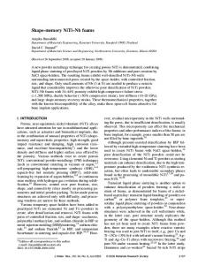
Exploring geometric morphology in shape memory textiles: design of dynamic light filters Isabel Cabral, AP Souto, Helder Carvalho and Joana Cunha Abstract Thermo‐responsive shape memory alloys are able to adopt a temporary configuration and return to their programmed shape when heated to a determined activation temperature. The possibility to integrate them in textile substrates creates potential to develop smart textiles whose shape change explores functional and expressive purposes. The aim of this research is to develop shape memory woven textiles in which dynamic behaviour achieves predefined geometric shapes. The requirement of geometric morphology was addressed through origami techniques. Combining foldability properties with shape change, it is possible to design textile structures with a variable number of layers. Difference in light transmittance is analysed according to layer variation. Experiments conducted explore methodological processes aimed at future developments in dynamic light filters research. Results highlight a process to design textiles with predefined geometric morphologies which can be activated electrically, and delineate a further study in order to improve the shape memory textile behaviour. Keywords Smart textiles, shape memory alloys, design, dynamic light, origami
Introduction The topic of Shape Memory Materials (SMMs) has been gaining increased attention from textile design and engineering. The possibility of conferring shape change in textile structures through an external stimulus creates an emergence of innovative properties and interactions for dynamic textiles. After having been deformed to a temporary shape, SMMs return to a pre‐programmed physical geometry through an external stimulus. This behaviour has been found in certain alloys, polymers, gels and ceramics and it 1,2 is called Shape Memory Effect (SME). Thermo‐responsive Shape Memory Alloys (SMAs) are metal compounds capable of converting thermal energy into mechanical energy. Their behaviour is based on two phase transitions named: Austenite (A) at high temperature phase; and Martensite (M) at low temperature phase, each one presenting different properties.3 When a SMA is deformed at M phase and temperature increases, it begins to transit to austenite phase at austenitic start temperature (As), completing the transformation at austenitic finish temperature (Af). There is a transformation of the alloy crystal structure that becomes cubic, after which the alloy returns to its memorized shape. By decreasing the temperature, the reverse transformation starts to happen at martensitic start temperature (Ms) and the process is concluded at martensitic finish temperature (Mf). There is no shape change 4 due to this transformation. When Mf temperature is attained, the alloy is ductile and can be deformed. The difference between the transition temperatures defines the hysteresis of the process. SMA also presents a behaviour called superelasticity or pseudoelasticity. This property is observed when, without any temperature change, the alloy is able to return to its original shape after a mechanical strain has been applied and is then withdrawn.5 The SMA which exhibits greater superelasticity (up to 8%) is Nitinol, a nickel and titanium alloy discovered by Buehler and co‐workers in 1963. Due to its increased properties in relation to other SMAs, research in this area has led to a great variety of applications. Available with diverse transition temperatures and forms (wire, tube, strip and sheet), Nitinol exhibits strong SME, pseudoelastic behaviour, high damping capacity as well as high 3,4 resistance to corrosion and abrasion. It is non‐toxic, biocompatible and it is less expensive than other SMAs. Over the past decades, SMAs have been implemented in technical applications, namely in automotive, 6 aerospace, robotics and biomedical fields. More recently, SMAs have become an exponent of research and
development in textiles. Besides functional possibilities, shape memory textiles are also being researched and designed to explore enhanced aesthetics and interactions. In the late nineties, functional protective clothing has been developed incorporating SMAs. An intelligent suit for firefighters incorporates Nitinol springs placed in between two fabric layers whose shape change creates an insulating air layer.7 The application of the pseudoelastic behaviour of SMAs has also been studied in ballistics, for example GEMTEX developed a textile substrate with SMA and Kevlar to improve high‐speed impact 8 resistance. In 2000, Marielle Leenders explored several shape change effects by stitching SMA wire with different shapes in woven textiles. The effects achieved by shrinking or rolling within different textures were applied on certain areas of shirts and in a jacket.9 Oricalco fabric, developed in 2001 by Corpo Nove through its spin‐off firm Grado Zero Espace, was the first example of Nitinol integration in a woven textile substrate. It was used to manufacture a shirt that in response to heat, recovers its original shape, having the rolled up sleeves acquired a new size according to their pre‐ programmed geometry.10,11 The fashion designer Hussein Chalayan, known as one of the pioneers of merging technology with fashion, presented a shape memory dress in his Before Minus Now, Spring/Summer 2000 collection. The dress with SMA stitched in its skirt, instead of being stimulated with thermal radiation, is heated with electrical current that 12 produces the phase transformation and therefore changes the skirt volume. Design research studio XS Labs also developed shape memory garments activated electrically. In 2005, they have experimented to pre‐program Nitinol in different configurations, such as curves and zigzags. However, they 13 found that with coil or spring shape a greater performance was attained. On the Vilkas dress, the Nitinol was stitched on cotton and the SME caused the fabric to wrinkle, thus revealing the wearer’s knee. The Kukkia dress has felt and silk flowers with Nitinol stitched to each petal to achieve an open and closed effect. Later, they developed the Skorpions collection to explore anthropomorphic qualities in garments through textile movement. 14 The Nitinol was hand‐stitched and embroidered to perform aesthetic experiences. Marcelo Coelho also relied on SMA incorporation with felt focusing on human‐computer interactions and the properties of shape change. He developed interfaces that studied topological, textural and permeable transformations.15 Regarding yarn spinning with SMA and following integration on textile structures, Chan, Winchester, Wan and Stylios conducted a research focused on aesthetics design. They have produced a variety of yarns with pre‐ programmed SMA as a core element, wrapped with conventional fibres. They found that the twist level and rollers’ speed were important parameters to be optimized in order to avoid SMA protruding from the yarn and reducing SME constraints.16 Initial experiments using the yarns for knitting, exposed limitations due to the lack of extensibility of the SMA yarn and propensity to deform when knitted. Better results were achieved introducing 17 SMA yarn formations in selected areas of the knitted structure. Tests aiming at weaving, with SMA yarns in the weft, revealed yarn end breaking when tension was too tight or slack. Samples were developed with SMA yarn formation with coil shapes, floating on the surface.18 A range of textures and sculptured woven and knitted fabrics were designed. Patrick Dyer alludes to the integration of Nitinol and the manipulation of woven fabrics. His research attained an understanding of the influence of cloth sett, woven structure, textile yarn and Nitinol selection in the mechanical shape transfer.19 Concerning experiments with SMA placed between two layers of fabric, Tatiana Laschuk and A. P. Souto have developed SMA bras, which in contact with skin recover their memorized shape. They have produced bra pads 20 with knitted Nitinol and cotton yarn. Conventional yarn was applied in order to provide a better processability. After heat treatment, using a ceramic die, the cotton materials burn and are removed from the samples, resulting in 100% SMA structures. They also developed woven pads; however, in this case, it was not necessary 21 to include textile fibres into the process. The woven samples achieved better performance. Techno Naturology, a hybrid word that combines nature and technology, was the concept that Elaine Ling addressed in her investigation. Focusing on hybrid materialization, through diverse techniques such as weaving, laser‐cutting and laminated surfaces, she studied and applied natural and man‐made responsive materials, namely wood, SMA and Shape Memory Polymers (SMP). Ling’s collections achieved mimicked tectonic movements in response to changes in temperature and moisture, reflecting the micro behaviour of how nature becomes evident.22,23 Other projects have integrated sensors in order to explore SME in response to diverse stimuli that activate SMA heating. Max Schäth developed Emotion: Outsourcing, a shape‐shifting garment that addresses the wearer’s 24 senses and feelings via SMA and integrated sensors. Patents concerning SMA integration have also been published. Examples are Pocket25 and Tactile feedback device26 registered by Philips. The projects discussed address diverse approaches regarding SMA training and how to integrate SMA within textiles. The materials’ systems studied are diverse and comprise different concepts, processes and product applications, attaining milestones in shape memory textiles development. The researchers also share common issues. SMAs memorize their shape at considerably higher temperatures than those supported by textile fibres. In this sense, they must be processed prior to their integration in fabric
manufacturing,20 if a 100% SMA textile is not the goal. Another aspect is related to the fact that textiles require a certain amount of stretch in the yarns to be processed. The low strain properties of SMAs represent a challenge when the material is to be woven or knitted.16 Textile structures’ characteristics and materials interaction can 27 also constrain the SME, reducing the ability to perform the shape change. In woven structures, a greater number of interlacings between the Nitinol and perpendicular warp threads has improved control and 19 integration of Nitinol in the textile. The SME analysed within the projects fulfils changes in textile texture, contractions, rolling up, forward and backward movement. This study aims to develop shape memory textiles that perform changes to predefined geometric morphologies. The first objective was to analyse the accuracy of the shape’s angles memorized in relation to the predefined geometry. Having achieved an understanding of the associated parameters, the question raised was how to integrate SMA wires in textile substrates that can perform predefined morphologies. The design concept inherent to the materials research hinges on the interaction of SME and aims to design dynamic light filters. Natural or artificial light is a physical phenomenon that plays an important role in human life. It makes visual perception possible, it influences our biological rhythms and, among other functional and aesthetic aspects, light 28 is also a key factor in designing atmospheres once it presents the ability to influence how space is experienced. Principles of lighting design are set through light properties and behaviour, concerning the optics domain, as well as application and control for a specific goal.29 Extrapolating technical perspectives, several artists and designers have been inspired by optical phenomena embracing conceptual and semantic relations. In parallel, light design has also been benefiting from technological advances, leading to lighting innovations intrinsically allied to issues as sustainability and interaction. Textiles have a long tradition of interacting with light, namely performing as light shades. This happens due to optical characteristics that textile substrates exhibit: when incident light is reflected at several angles – diffuse reflection – textiles scatter the harsh light and soften it; when incident light passes through a translucent 30 substrate, light can be partially transmitted – transmittance – depending on the proportion absorbed. To achieve differences in light intensity, several types of lamps or dimmers are normally applied. In this study, the change of light intensity is addressed without acting upon the light source. With dynamic behaviour of shape memory textiles, it is possible to develop textile morphologies that present areas with different number of layers, which will interfere with light transmittance.
Approach: Textile morphology implemented by base origami structures Developing shape memory textiles with the ability to perform predefined geometric configurations also demands a study of the textile physical form or shape – morphology.31 In this study, the solution for the requirement of geometric rigor and generation of morphologies with different number of layers was developed through origami techniques. To illustrate the origami folds, an origami diagram (or crease pattern) is implemented. Origami diagrams consist of drawing mountain and valley folded lines necessary to depict the origami creases. They can be represented in different ways; in this paper a black continuous line for mountain fold and red dashed line for valley fold were applied. There are origami base folds that can be combined to develop more complex models. Origami tessellation is 32 based on repetition of common base patterns of fold pleats and twists, creating intricate patterns. These origamis can display a property of flat foldability, which means the origami model is flat after being folded. Surfaces folded through tessellation techniques create areas with different amount of layers. In shadowfolds, Rutzky and Palmer combine the concept of pleat and translucency for origami tessellations developed in textiles. They highlight the expressive quality that these models may exhibit: “Some applications will take advantage of light shining through and others will show the richness of folds that have a depth all their 33 own”. In this research, the translucency of textile origamis is studied in a dynamic perspective, in which the interaction of the shape memory textile with light will design dynamic light for expressive and functional purposes. The study of the SMA integration in textile origamis will focus on two origami bases: “Waterbomb” and “Squaretwist” (Figure 1). They were chosen for the different level of complexity that they might present for shape memory textile development and performance. Waterbomb is based on pleats while squaretwist displays pleats and twist. The origami patterns that can be designed with these base folds are limitless.
Figure 1. Waterbomb and Squaretwist diagrams (left and right, respectively)
The predefined geometry of the shape memory textiles dictates the Nitinol wires’ shapes, according to the diagrams and the specific location where each wire will be integrated. This condition highlights the drawing and manufacturing of different wire geometries to be embedded in the same textile structure, as will be illustrated in a later section.
Preliminary experiments
Light filters using simple pile‐up of textile layers
Materials and methods. To understand how the amount of layers can transform the fraction of incident light that goes through them, a light meter measurement was conducted on a textile substrate with the following characteristics: 50% CO 50% PES plain weave, 115 g/m2, 15,0 and 15,5 warp and weft yarns (tex), with a density of 41 ends/cm and 31 picks/cm. To measure light intensity, a DeltaOhm – HD 2302.0 luxmeter was used. In a dark room, different amounts of textile layers were placed on the open face of a light box set in vertical position, 1m from the luxmeter. The lamp was turned on and the luxmeter values were recorded on 3 points of the sample. Results. Table 1 shows the mean values of measured light intensities. Table 1. Mean values of light intensities Nº of layers
Lux (lx)
Difference (%) 1 layer to x layers
1
13,38
‐
2
7,62
43,05
3
5,17
61,36
4
3,83
71,38
5
2,64
80,27
6
2,09
84,38
The values of the experiment conducted relate to the specific characteristics of the textile substrate applied. However, they set an initial value of the transmittance variation that might be achieved with different number of textile layers. According to the results shown in Table 1, it is possible to conclude that the variation of the number of textile layers achieves a considerable change of light transmittance. From one to two layers, the reduction was about 43%, additional layers produced a transmittance decrease of approximately 10% per layer, until five layers. From five to six layers the difference was only 4%. The values attained until five layers were considered significant in order to design dynamic light filters and present a base framework for the following design process. In Table 1, the measurement of light intensity comprises the transmittance of different amounts of piled up textile layers. The approach through origami techniques achieves layer variation in specific areas of the light filter, depending on the diagram designed. This study will be preliminarily approached in the next section.
Light filters using base origami structures
Materials and methods. For a preliminary analysis of the phenomena of the transmittance variations that the folding and the unfolding may produce, and for a proof‐of‐concept in an initial stage of the work, two textile samples folded through the selected origami bases were developed. The unfolding of the samples was carried out manually and focused on the creation of spaces between the folds, instead of achieving the complete unfolding of the textile surface. To evaluate transmittance using these origami samples, the luxmeter was placed 5cm above the light box top, pointing to a white surface placed 1,0m in front of the light box, in a first measurement cycle, and 0,5m in the second measurement. Light intensity values were recorded on three points to quantify the differences in transmittance achieved. Results. The resulting model presented in Figure 2 consists of pleated squares created by waterbomb folds in each square vertex. The unfolding was carried out by pulling up the centre square, causing a volume increase with a partial unfolding of the waterbomb folds. In Figure 3, the model is composed of squaretwist folds, regularly aligned. This origami presents vertical and horizontal tabs created by the twist of the squares. The shape change was produced by folding the horizontal tabs orthogonally to the origami surface.
Figure 2. Study model waterbomb fold based (folded and unfolded)
Figure 3. Study model squaretwist fold based (folded and unfolded)
Table 2 shows the measured light intensities of the folded and unfolded models. Table 2. Mean values of light intensities
Samples
Waterbomb based
Squaretwist based
Distance (m)
Lux (lx)
Folded
Unfolded
Difference (%) Folded to Unfolded
1,00
2,54
6,55
61,22
0,50
5,05
11,73
56,95
1,00
1,42
5,38
73,61
0,50
2,18
7,44
70,70
The results show a difference of light transmittance between 61% and 57% with the waterbomb based sample and between 74% and 71% in the squaretwist based sample.
Performance of Nitinol and SME training
Materials and methods. The Nitinol wires handled in this study were supplied by Saes Getters, in cold work, with three diameters: 0,2, 0,3 and 0,5mm. The SMA transformation temperature selected is body‐temperature (As +30°C). The heat treatment process was carried out in a Naber D‐2804 furnace. The initial study aimed to optimize the heat treatment parameters for the selected SMA considering the geometries defined. In order to train the SME of the Nitinol wire, it is necessary to fix it in the desired shape and
condition it to high temperatures. A 90° angle was selected in order to study the accuracy of Nitinol performance in reacquiring the programmed shape. The experiments conducted to train the Nitinol took into consideration the annealing parameters indicated by the supplier – temperature and duration of the heat treatment. It was advised to apply a temperature between 450°C and 550°C. Duration was suggested to be tested, highlighting that long periods of time could interfere with the wire’s fatigue and the ability to perform repeatable accurate predefined shape changes throughout several cycles. A stainless steel sheet with 1mm thickness was used to produce a die to create the desired shape. The exact location of the wire crease was set with an orifice through which the wire is led, and the wires were fixed with screws and nuts (Figure 4).
Figure 4. Nitinol die setup
First experiments were carried out for 5 minutes, at temperatures of 500°C and 550°C. New experiments were developed at a temperature of 550°C and varying the period of time for each sample set – 20, 15 and 10 minutes – a sample set being composed by five Nitinol samples of each of the three wire diameters, totalling fifteen. The prepared samples were then analysed by submitting the wires to five cycles of deformation and heat stimulus. For this purpose, they were placed one at a time in a heat chamber, after being deformed at M phase. In the chamber, temperature was increased from 20°C to 45°C (Af temperature) and, for each cycle, the sample was removed, placed on a surface with a guideline and photographed. The angles attained on the captured images were measured in Adobe Illustrator software (Figure 5). Results. Figure 5 shows the angles measured on the samples treated during 15 minutes.
Figure 5. Angle values attained throughout 5 cycle tests for each Nitinol wire, with heat treatment during 15 minutes. Upper row to lower row: 0,2; 0,3 and 0,5 mm diameter
The angles measured above 95° in the samples that were heat treated during 5 and 10 minutes. At 20 minutes, the wires presented a significant variation of angles between the different cycles. In the wires treated during 15 minutes, angles between 90° and 92° for Nitinol of 0,2mm thickness (1st row of Figure 5); 90° to 91° for Nitinol of 0,3mm (2nd row of Figure 5) and of 0,5mm (3rd row of Figure 5) were obtained. Considering that the results attained with the heat treatment of 550°C during 15 minutes present small, acceptable variations from the pre‐programmed 90° angle, this condition was selected for further experimentation.
Production of samples of the base folds
Materials and methods. In order to study the shape change behaviour within predefined geometric configurations, the aforementioned origami base folds – waterbomb and squaretwist – were implemented on basis of woven samples, by integrating Nitinol wires of the three selected diameters. The integration of the Nitinol wires was done in a plain weave structure. This selection was due to the regularity and maximum number of interlacings of this woven structure. It was defined that the final samples dimensions would be 12x12cm with Nitinol wires inserted in the weft at every 1,5 cm. To achieve the final unfolding effect, the shapes to be memorized on each of the Nitinol wires depend on the origami morphology while folded. To define these wire geometries, a paper model with horizontal lines spaced by 1,5cm was folded with the shape of the selected origami. The resulting wire geometries were then taken from the model. Each model includes seven Nitinol wires. Some of the wire configurations are equal. The waterbomb model contains four different wire shapes (Figure 6), whilst the squaretwist model has three (Figure 7).
Figure 6. Waterbomb model open and closed (left and centre); SMA shapes (right)
Figure 7. Squaretwist model open and close (left and centre); SMA shapes (right)
After defining the Nitinol wire shapes, the die for each geometry was designed and produced (Figure 8). The wires’ extremities were fixed with screws and the wire shape followed the die geometry by passing orifices placed at the exact crease locations.
Figure 8. Waterbomb dies (left); Squaretwist dies (right)
Finally, samples of the base structures were produced, which involves the following steps: training the Nitinol wires with the predefined shapes; setting up the loom and weaving the samples. A total of six samples were developed – for each origami model (waterbomb and squaretwist) were produced three samples with the different SMA wire thickness (0,2; 0,3 and 0,5mm). Nitinol training consisted of fixing the wire, one at the time, in each die and placing it in the furnace for 15 minutes, which was pre‐heated at 550°C. When removed from the furnace, the samples were exposed to a temperature of approximately 10°C and were then deformed to a straight shape.
To weave the samples, a handloom was set up with 3/24 cotton yarn (148,7 tex) warp, 16 ends/cm. The width of the warp was 12cm. The same yarn was used for the weft and one specific pre‐trained Nitinol wire was inserted every 1,5 cm, according to its position in the origami diagram, into a plain weave structure. Results. To analyse the behaviour of the developed study samples, a video and photographic record was made. The samples were deformed at M phase, placed in a horizontal surface and thermal activation was induced with a heater, attaining approximately 45°C. Figure 9 illustrates the waterbomb sample performance in five different phases, with the first row displaying the images of the sample produced with 0,2mm Nitinol wire; the second row with 0,3mm and the third row with 0,5mm. Figure 10 follows the same sequence for squaretwist samples. Figure 9. Waterbomb samples performance during thermal activation (1st row 0,2mm wire sample, 2nd 0,3mm and 3rd 0,5mm) Figure 10. Squaretwist samples performance during thermal activation (1st row 0,2mm wire sample, 2nd 0,3mm and 3rd 0,5mm)
The samples developed achieved different performances depending on the wire thickness and origami diagrams. The shape change transfer follows the predefined diagrams, however, final geometries did not reach the exact angles defined and trained in the Nitinol wires. In the waterbomb configuration, the sample with 0,5mm Nitinol exhibits better shape recovery than the ones of 0,3mm and 0,2mm. Conversely, in the squaretwist origami, the 0,5mm sample achieved the lowest performance. Due to the existence of more creases in the squaretwist diagram than in the waterbomb one, the woven structure appears to have a higher constraining effect on thicker wires. Better performance on squaretwist samples was achieved with 0,3mm and 0,2mm Nitinol. The shape change process was recorded in three videos for each sample. In both origamis, the samples with 0,2mm Nitinol wires needed more time to recover their shape when compared with other samples, of approximately 50 seconds. In the waterbomb diagram, the average duration for samples developed with 0,3mm and 0,5mm was of 18 seconds, whilst in the squaretwist diagram, the values were slightly higher: 22 seconds for 0,3mm and 25 seconds for 0,5mm samples. Difficulties were found in deforming the samples on flat surfaces. It was not possible to deform the Nitinol creases to assume a straight shape by hand deformation. In some of the creases, wire protruding the woven structure was observed. This was more evident in samples with 0,5 mm thick wire.
Nitinol 0,3mm thickness wire was selected for the following developments, given that its overall behaviour was found more stable in regards to the aforementioned variables. Furthermore, weave density is to be increased to improve shape transfer of the Nitinol integrated in the textile.
Final prototype
Materials and methods The prototype development applies the process setup proposed in the preliminary experiments, to the design of a shape memory textile based on an intricate origami. To define the textile morphology, the base fold selected was the squaretwist. In the folded state, this origami presents a square area with five layers, four tabs with three layers (in the area exterior to the square) and a remaining area with one. The tabs are two by two, parallel to the correspondent square diagonals (vertical and horizontal). When tabs with the same direction are pulled up to an orthogonal plane, in relation to the folded origami, it is possible to obtain a valley fold in a square diagonal attaining a variation in the amount of layers, as demonstrated in Figure 3. When one square and two tab areas are folded, what remains in the origami surface are two tabs with three layers and one layer in the overall structure. The shape change described was implemented in the prototype development. The origami diagram designed combines eight squaretwists with asymmetrical distribution in a quadrangular frame. Dash‐dot green lines in the diagram presented in Figure 11 depict Nitinol wires placement. Seventeen Nitinol segments were defined.
Figure 11. Prototype diagram
As previously explained for the base folds, once again the origami folds define the geometry that the wires should be trained with. After folding the model with the configuration that should be assumed, when heated, each wire shape was drawn (Figure 12 left) and subsequently, the die for each shape was drawn and produced (Figure 12 right). This model displays five different wire shapes. Numbered from top to bottom, A corresponds to wire number 1, 2, 4, 5, 6, 8, 9, 10, 12, 13, 14, 16, 17; B is 3; C is 7; D is 11 and E is 15.
Figure 12. Nitinol wires’ shape (left); Nitinol dies’ shape (right)
Nitinol heat treatment was conducted with the same equipment applied in the preliminary study. For the Nitinol size defined, annealing parameters were retested and the values set were 550°C for 10 minutes. The weaving process was developed in an electronic Jacquard loom with 3456 hooks and a Bonas Series 200 Controller. The warp has a 30,8 tex cotton yarn and a density of 38 ends/cm. The weft has 11 picks/cm with a 17,7 tex polyester yarn, plus a Nitinol wire each at distances of 2 cm. Nitinol segments have been integrated manually in order to assure accuracy within the diagram. Each wire was deformed to a straight shape at M temperature and inserted in each section of 21 picks. To assure a straight shape in the correct location, the wire ends were held during the next weft textile yarn insertion.
Electrical activation The thermal activation of the shape memory textile was produced through the flow of an electrical current. The process by which electrical current flows through a resistor and releases heat – the Joule effect also known as 12‐15, 24 Joule heating – is commonly applied to heat SMAs. The electrical current required to attain the Nitinol activation temperature depends on the Nitinol characteristics and ambient temperature. A study to specify the current value was conducted, to ensure that the Af temperature would be attained (45°C) without overheating the wire. The experiment took place at an ambient temperature of 23,8°C. For each Nitinol segment integrated in the woven structure, a specific voltage was applied using a TENMA 72‐8695 power supply. The resulting electrical current was measured and a thermal image was recorded with a TESTO 876 Infrared camera. For thermal isolation from the table surface, a polyethylene board was placed below the prototype. Nitinol has a tough oxide layer that does not allow an accurate resistance measurement and presents difficulties in joining processes, such as soldering. A mechanical abrasion of the Nitinol ends was done prior to the described measurement. Voltage variation from 0,5V to 3,0V was supplied in intervals of 0,5V increases. The electrical current values attained for each segment were similar, as well as their temperature. Mean values are presented in Table 3 and thermal images of Nitinol wire number 3 are presented in Figure 13. Table 3. Mean values of electrical current and maximum temperatures attained V (V)
I (A)
temp. (°C)
0,50
0,12
26,20
1,00
0,23
27,80
1,50
0,37
32,20
2,00
0,51
37,80
2,50
0,63
46,80
3,00
0,75
54,10
Figure 13. Thermal images of Nitinol wire number 3 during voltage variation
An analogous experiment was conducted linking the Nitinol segments two by two, in a series circuit. Relation between electrical current and temperature was similar to the results within one segment, as expected. As will be explained later, the series connection will allow simplifying the electrical circuit used to control the SME. Despite of a mean maximum temperature of 46,80°C attained with 0,63A, thermal images demonstrate that wire temperature is not homogeneous. Also, ambient temperature during the tests can be considered slightly higher than the common definition of room temperature. A current of 0,7A was found to be an adequate value to drive the Nitinol wires. In order to achieve a controlled heating of the Nitinol wires, and considering that the simultaneous activation of all 17 wires would require a considerable amount of current, a sequential activation was implemented. For this purpose, an Arduino microprocessor board was used to control the process. The power stage was implemented using ULN2003A Darlington‐transistor arrays, which feature 7 channels with a maximum current of 0,5 A each. To drive the wires with 0,7 A, it was necessary to use two channels in parallel for each wire, reducing the number of controllable wires to 3 per each ULN2003A. To simplify the circuit, wire segments on the textile were paired and connected in series, which allows reducing the number of wires to control to 8+1 (8 pairs and one single), using three ULN2003A chips instead of 6. Figure 14 shows the circuit diagram of the power stage. The Nitinol wires are connected in series with pull‐up resistor Rp, which has been dimensioned to allow a current of 0,7 A. All of the resistors are of equal value except the one which drives the single wire. Figure 14. Circuit diagram, with ”N” representing the Nitinol wires
Figure 15 shows the very simple code used to activate the wires sequentially, with a heating time of 6 seconds and a delay of 1 second between channels.
Figure 15. Arduino code
Having completed the prototype development, an analysis focused on shape change performance, thermal measurement and transmittance variation was conducted. The shape change performance was recorded on video and the frame of the final textile morphology attained was compared with the predefined geometry. A thermal imaging record was made to analyse temperature in
each Nitinol wire during current flow. Light transmittance variation was measured before and after activation (temperature As, respectively), with a similar setup described for the results presented previously in Table 2.
Results and discussion The photographic record of the prototype, before and after activation, is presented in Figure 16. For a visual comparison of the morphology achieved and defined, an image of the paper model depicting the defined activated morphology was also included. Figure 16. Prototype before activation (left); activated (middle) and paper model (right)
It is possible to conclude that some areas achieved equal or similar configurations to the predefined ones. There is a main incongruity in the bottom right square area, as the tabs are not perpendicular to the prototype surface, resulting in a non‐folded square. The prototype was also analysed regarding textile and Nitinol materials’ interaction. There are some areas with Nitinol wire protrusion; however, they are less prominent than in the study samples. Also perceived is the ability of the Nitinol to slide out of the textile structure and rotate around its axis. Thermographic images have presented some issues on the electrical activation. Due to the origami structure characteristics and the wire protrusion in specific crease areas, some Nitinol segments are close or in contact with other segments. This compromises the planned electrical current flow and the temperature that needs to be attained. Figure 17 illustrates the activation of Nitinol wires number 9 and 10. It is possible to detect a short circuit area, in which there is an overheating, as defined by the dark red area, being the remaining wire below the activation temperature. This explains the described anomaly in the bottom right area of the textile. Figure 17. Thermal images of Nitinol number 9 and 10, being activated
The aforementioned issues are due to the smoothness of the Nitinol wire and the fact that they are not electrically isolated. This finding has delineated the development of a future study with the purpose of implementing a Nitinol coating process in order to increase adhesion and thus avoiding slip, rotation and protrusion of the Nitinol from the textile substrate; to isolate the wire to avoid issues with undesired electrical contact between wires. The origami scale defined also appears to be relatively small in comparison to the textile’s thickness. In some areas, the overlapped layers constrain the SME, reducing the ability to perform with greater accuracy within the predefined geometry.
During the observation and recording of the shape change, transmittance variation was perceptible. The light intensity measurement provided a quantification of the variation. The luxmeter was pointed to a white surface placed 1m from the light box and the values were recorded on three points. Mean values reached a percentage difference of 42% (Table 4). Table 4. Mean values of light intensity
Lux (lx) tempAf
Difference (%) tempAf
0,56
0,97
42,27
Conclusions In this study, a novel approach was conducted in regards to: Nitinol wire shapes being defined accordingly to a textile geometric morphology; integration of Nitinol segments with different shapes in the same woven textile structure; and interaction of the textile SME with light transmittance. Design and development of shape memory textiles encompass a systematic process. The material research conducted outlines a preliminary study and a prototype development, which proposes a process to develop shape memory textiles with the ability to perform shape change similar to predefined morphologies. The workflow setup consists of: defining the origami morphology and shape change; selecting the Nitinol wire and defining geometries, depending on their integration in the woven structure; drawing and production of the dies; optimizing the annealing parameters following the Nitinol heat treatment; integrating Nitinol wires in the weaving process. The prototype developed presents areas in which the shape change performance is similar to the predefined geometry. However, there were sections in which the shape change did not occur or attained a folding effect with a lower angle than the predefined one. The analysis has highlighted the need to reduce the Nitinol smoothness in order to improve their mechanical interaction with the textile structure, as well as electrically isolate the Nitinol wires. Textile morphology definition, based on origami techniques to define Nitinol geometries, was found to be successful in the design of shape memory textiles with dynamic light filter behaviour. Despite the requirement of prototype improvement, it was possible to change the number of layers, attaining a light transmittance variation of 42%. Bearing in mind the perspective of a new generation of textile products, the results set a framework for future developments in interactive textile morphologies, enabling design of dynamic light scenarios with shape memory light filters, as well as other applications.
Acknowledgement This research is financed by FEDER funds through the Operational Programme for Competitiveness Factors ‐ COMPETE and National Funds through FCT ‐ Foundation for Science and Technology under the project SFRH / BD / 87196 / 2012. The authors would also like to express their acknowledgment to FCT and FEDER‐COMPETE funding, under the project PEst‐C/CTM/UI0264/2011.
References 1. Sun L, Huang WM, Ding Z et al. Stimulus‐responsive shape memory materials: a review. Mater. Des. 2012; 33: 577‐640. 2. Tao X. Smart Fibres, Fabrics and Clothing: Fundamentals and Applications. Cambridge: Woodhead Publishing Limited, 2001. 3. Honkala M. Introduction to Shape Memory Materials. In: Mattila H (ed) Intelligent Textiles and Clothing. Cambridge: Woodhead Publishing Limited, 2006, pp. 83‐103. 4. Kumar PK and Lagoudas DC. Introduction to Shape Memory Alloys. In: Lagoudas DC (ed) Shape Memory Alloys: Modeling and Engineering Applications. New York: Springer, 2008, pp. 1‐51. 5. Ōtsuka K and Wayman CM. Shape Memory Materials. Cambridge: Cambridge University Press, 1998. 6. Jani JM, Leary M, Subic A et al. A review of shape memory alloy research applications and opportunities. Mater. Des. 2014; 56: 1078‐113.
Clevertex. Report on Intelligent Textiles: State of Art, http://www.clevertex.net/Image/documents/State%20of%20the%20art.pdf (2005 accessed 21 September 2011). 8. Boussu F and Petitniot J. Development of Shape Memory Alloy Fabrics for Composite Structures. In: Mattila H (ed) Intelligent Textiles and Clothing. Cambridge: Woodhead Publishing Limited, 2006, pp. 124‐142. 9. Leenders M. Shape Memory Textiles, http://photorepeats.com/en/work/shape‐memory‐textiles/ (accessed 2 September 2013). 10. Quinn B. Textile futures: fashion, design and technology. Oxford: Berg, 2010. 11. Grado Zero Espace. Oricalco: Shape Memory Fabric, http://www.gzespace.com/gzenew//index.php?pg=oricalco&lang=en&ch=1&PHPSESSID=9eade2d92bba0f9f 5e401362dc179181. (accessed 2 September 2013). 12. Lee S, Preez W and Jones NT. Fashioning the Future: Tomorrow's Wardrobe. London: Thames & Hudson, 2005. 13. Berzowska J and Coelho M. Kukkia and Vilkas: Kinetic Electronic Garments. In: Proceedings 9th IEEE International Symposium on Wearable Computers, Osaka, Japan, 18‐21 October 2005. 14. Seymour S. Fashionable Technology: The Intersection of Design, Fashion, Science and Technology. Wien: Springer, 2008. 15. Coelho M and Zigelbaum J. Shape‐Changing Interfaces. Personal and Ubiquitous Computing 2011; 15 (2): 161‐ 173. 16. Chan YYF, Winchester RCC, Wan TY et al. The concept of aesthetic intelligence of textile fabrics and their application for interior and apparel. In: Proceedings of IFFTI International Conference, Hong Kong, 7‐9 November 2002, pp.458‐71. 17. Winchester RC and Stylios GK. Designing Knitted Apparel by Engineering the Attributes of Shape Memory Alloy. International Journal of Clothing Science and Technology 2003; 15(5): 359‐366. 18. Vili, YC. Investigating Smart Textiles Based on Shape Memory Materials. Text. Res. J.2007; 77(5): 290‐300. 19. Dyer P. The integration of Nickel‐Titanium shape memory alloys and the manipulation of woven structures. Doctoral Thesis, University of Brighton, England, 2010. 20. Laschuk T and Souto A. Incorporation of SMA Technologies in Fashion Underwear Apparel. In: Proceedings of Ambience 08. Borås, Sweden, 2‐3 June 2008, pp. 215‐18. 21. Lashuk T. Application of smart textiles to fashion textile products. Máster Thesis, University of Minho, Portugal, 2008. 22. Ling ENL. Techno Naturology. http://www.elaineyanlingng.com/?page_id=19. (nd, accessed 2 September 2013). 23. Dieffenbacher F. Fashion Thinking: Creative Approaches to the Design Process. London: AVA Publishing, 2013. 24. Seymour S. Functional Aesthetics: Visions in Fashionable Technology. Wien: Springer, 2010. 25. Farringdom J and Gough PA. Pocket. Patent US 6834797 B2, USA, 2004. 26. Van Heerden CR and Marmaropoulos G. Tactile feedback device. Patent US 20030181116 A1, USA, 2003. 27. Stylios G. Engineering textile and clothing aesthetics using shape change materials. In: Mattila H (ed) Intelligent Textiles and Clothing. Cambridge: Woodhead Publishing Limited, 2006, pp. 165‐190. 28. Karlen M, Benya J and Spangler C. Lighting Design Basics. Hoboken, NJ: John Wiley, 2012. 29. Yot R. Light for Visual Artists: Understanding & Using Light in Art & Design. London: Laurence King, 2011. 30. Ganslandt R and Hofmann H. Handbook of Lighting Design. Erco: Lüdenscheid, 1982. 31. Hensel M, and Menges A. Towards an Inclusive Discurse on Heterogeneous Architectures. In: Hensel M and Menges A (eds) Morpho‐Ecologies. London: AA Publications, 2006, pp. 16‐60. 32. Gjerde E. Origami Tessellations: Awe‐Inspiring Geometric Designs. Massachusetts: A K Peters, 2009. 33. Rutzky J and Palmer CK. ShadowFolds: Surprisingly Easy‐to‐make Geometric Designs in Fabric. New York: Kodansha International, 2011, pp. 18. 7.