a free-flyer (i.e. without contact); they can be given by the user through ..... the IEEE-RAS International Conference on Humanoid Robots, 2003. [4] J. Kuffner, S.
Exploring Humanoid Robots Locomotion Capabilities in Virtual Disaster Response Scenarios Karim Bouyarmane∗ , Joris Vaillant† , Franc¸ois Keith† and Abderrahmane Kheddar†
† CNRS-AIST Joint Robotics Laboratory (JRL), UMI3218/CRT, Tsukuba, Japan CNRS-UM2 Laboratoire d’Informatique de Robotique et de Micro´electronique de Montpellier (LIRMM), France ∗ ATR Computational Neuroscience Laboratories, Kyoto, Japan
Abstract—We study the feasibility of having various humanoid robots undertake some tasks from those challenged by the DARPA’s call on disaster operations. Hence, we focus on locomotion tasks that apparently require human-like motor skills to be achieved. We use virtual scenes under the fully3D-modeled-environment assumption. The robot autonomously plans and executes the motion with a high-level goal specification, such as reaching a global position or a particular contact state. We assess the feasibility according not only to the robot kinematics, but also to whole-body dynamics, nondesired collision avoidance, friction limits, and actuation limits. The results –the controlled motions– are demonstrated in the accompanying video.
I. I NTRODUCTION Disaster response is attracting attention from the robotics research community, and even more since the Fukushima Daiichi nuclear power plant accident that followed the 2011 Great East Japan earthquake and Tsunami. As a concrete materialization of this increasing interest, a challenge is proposed by the American Defense Advanced Research Projects Agency (DARPA) [1] to use robots in disaster-hit facilities that were made too hazardous for direct human operator intervention. We take this opportunity to study some aspects of the problems raised by this challenge and propose our solution, using some of the suggested challenge scenarios as benchmarks for evaluation. The particular aspects of the challenge we are addressing are those related to motion planning and control in a fully modeled environment, for the tasks of navigation/locomotion-like nature. It is worth noting that the challenge does not impose any constraint on the design of the robot, but it is generally agreed through common sense that the humanoid design fits the specification of the problem, since the latter involves navigating in a humanmade environment that was engineered to comply with human morphology (e.g. industrial ladder) or using pieces of equipment that were made for human operator (e.g driving a utility vehicle). We do not claim that the humanoid design is the optimal choice; we rather presume that it is an acceptable one and confirm this assertion through our study. The study is meant to validate kinematics, dynamics, actuation limits, of example humanoid platforms that we will access in the near future (Kawada Industries’ HRP-2, HRP-4, and Aldebaran’s Romeo) in the proposed motion contexts.
We thereby selected three benchmarking scenarios inspired by the challenge: climbing an industrial ladder, getting into a utility vehicle, crawling about in an unstructured environment. From a motion planning and control perspective, these three scenarios span a large spectrum of skills such as: mixing up grasping with hands and finite-friction contacts, collision avoidance in cluttered environment, self-collision avoidance for whole-body motions, changing the contact configuration with environment in an acyclic way (as opposed to locomotion using cyclic gaits). Approaches that assume the humanoid robot as walking biped [2], [3] or, on the opposite, that plan whole-body motions with fixed foot location [4], [5], are thus not sufficient to deal with the problem. Since these scenarios and corresponding expected motions seem to be rather unrelated in their structure, one can be tempted to tackle the different problems on a case-by-case basis, for example focusing a particular study for a ladder climbing motion by specifying a cyclic behavior of the arms and limbs or less by specifying the potential contact locations [6]. We however propose a unified formulation and solve all the problems within the same framework, aiming at high-level autonomy of the robot. This formulation is based on our multi-contact motion planning paradigm [7]–[9], which consists in first planning a multi-contact sequence then plans/executes the motion along this sequence. Moreover, we brought additional functionalities that were not tackled in our previous publications, namely on the QP multi-contact controller. The rest of the paper is organized as follows: we present the humanoid systems we consider for our study and the simulation framework we use (Section 2). We then recall the multi-contact motion planner and corresponding controller (Section 3). Section 4 presents the achieved results. Section 5 concludes the paper with a discussion and perspectives. II. H UMANOID S YSTEMS AND S IMULATION F RAMEWORK Three humanoid robots are considered in our studies: Kawada Industries’ humanoids HRP-2 [10] and HRP-4 [11] with AIST software, and Aldebaran’s Romeo. General specifications are available to the public or the buyer; therefore, we do not mention them here. We have access to the CAD, kinematic, dynamic and actuators models for the three robots. The reason of this choice stands in the fact that we have
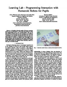
access to the real platforms currently (HRP-2) or in the near future (HRP-4, Romeo). As a simulation framework, we are using AMELIF [12], an integrated C++ object-oriented software that we developed as independent modules of the main components necessary for interactive simulation of robotic and virtual humanoids. Contact forces are computed using collision-detection modules with constraints-based methods and can be used in interactive force feedback devices. All the components of our multicontact planner build on the set of basic robotic routines implemented in AMELIF. Fig. 1 illustrates the three robot models loaded by the AMELIF visualizer.
III. M ETHOD OF R ESOLUTION To solve the problems at hand we use our multi-contact planning framework [7], that we recall in this section. This framework gathers four interrelated main components. Initial posture and contacts Environment contact areas Setting contact areas
Guide path planner
Milestone configurations
Termination condition
- Robot model - Environment model - Posture cost function - Interaction model
Multi-contact search
Set of contacts
Sequence of multi-contact transitions
Posture
Physicsconstrained IK solver
Multi-contact Motion controller
Fig. 2. Global view of the multi-contact planner with the four modules: (1) the Guide path planner plans path of the free-floating humanoid and output milestone configurations, (2) the multi-contact search algorithm explores possible contact supports and transition, thanks to (3) the physicsconstrained inverse kinematics (IK) solvers, it is able to keep only viable postures of the contact configuration and humanoid postures. The latter three components result in a sequence of multi-contact transitions and configurations that are sent to the multi-contact motion controller to be realized by the humanoid robot in the real environment.
Fig. 1. The humanoid robot models as loaded by AMELIF. From left to right: Kawada Industries’ HRP-2 and HRP-4 and Aldebaran’s ROMEO.
The scenarios that we consider in this paper, and according to the DARPA description [1], they correspond to: •
• •
from task 1: ingress/egress a car model suggested as potential candidate by the call (Polaris’ RANGER RZR S 800); from task 2: crawl about a rubble; from task 5: climb an industrial ladder.
In these scenarios, we first define the allowed contact areas on the robots and the environment. Then we define the initial posture and contacts for the robot. Eventually, we also define milestone configurations in different ways. They can be the outcome of a guide path planner considering the robot as a free-flyer (i.e. without contact); they can be given by the user through tele-programming interfaces [13]; or they can be learned from motion capture data. Then the contact planner is run, and upon success provides the sequence of multi-contact transitions through which the robot goes to achieve the given task-goal. The sequence of multi-contact transitions is then given to the multi-contact motion controller that achieves the sensory closed-loop motion under a finite state-machine that triggers each phase in conjunction with sensory events. The multi-contact motion controller is tested in some case studies with perturbations (the robot is hit during the motion) or assuming simple geometry uncertainties, such as the actual new contact support not being configured at the position assumed in the multi-contact planning phase.
A. Guide path planner The purpose of the guide path planner is to avoid local minima during the greedy multi-contact search phase [14]. The guide path planner considers the robot as free-floating in the 3D workspace, so as to be able to readily use existing path planning algorithms (RRTs or PRMs) only adapting the random sampling method to the particular need of our framework. Every sampled configuration of the robot –biased toward some reference human-like postures such as standing or sitting postures and toward some reference orientation of the free flyer– is projected close to the environment components (“obstacles” as considered by the path planner, but “contact supports” as considered by the multi-contact motion planer) with a rough approximation of static equilibrium criterion. The resulting path in the C-space is not meant to be physical, the robot cannot execute it since it is floating in the free-space along the path, but it is used as a guide for the multi-contact search phase. We use a linear-interpolation “steering method” (interpolation method between sampled configurations). The guide path is thus piecewise linear, and we store the interpolated configurations along the path as a sequence of milestone configurations. B. Physics-constrained IK solver The purpose of this component of the framework is to generate a posture of the robot that meets some goal contact locations [15]. The robot is initially floating in the free-space, and an optimization process brings the bodies of the robot to the desired contact locations. The posture is constrained
by static-equilibrium condition (under gravity, contact forces, and actuator torques) and by actuation torque limits. It should avoid any undesired collision (except the desired contacts), avoid self-collision, and remains within joint limits. Contact forces should lie within their static friction cones. We define three types of contacts: (i) regular contacts, (ii) zero-force contact, in which the robot should position its contact body and is not allowed to exert a contact force on it, and (iii) floating zero-fore contacts, in which we do not specify the exact location on the environment contact surface. To solve all these constraints simultaneously, we express the optimization problem in terms of variables of both the configuration (6D floating-base and joint angles) and the contact forces of the regular contacts. We then express the constraints as non-linear equalities and inequalities on these variables, and provide algorithms for gradient derivations. For the inequality constraint describing the collision avoidance to be continuously differentiable, we use a collision detection algorithm that defines an inter-penetration distance (GJK algorithm), and cover the bodies of the robot with strictly convex bounding volumes [17] [18]. The cost function we aim at optimizing depends upon the context of the multi-contact search algorithm as follows. C. Multi-contact search algorithm This algorithm finds a sequence of multi-contact transitions between the initial and goal configurations of the robot [16] [8]. It is a best-first search algorithm on set of contacts. We successively target as a goal configuration each of the milestone configurations provided by the guide path planning component, until reaching the last goal configuration; which is the last milestone. • Initialize a search tree and priority queue (ordered by the distance to goal) with the initial contact set. • Enter the following loop – Pop best element (contact set) of the priority queue, according to the cost function (distance to goal) – For all possible(/allowed) matches of a robot contact surface with an environment contact surface: ∗ Define a zero-force floating contact between the two surfaces, add this contact to the current best contact set, and call the IK solver, with the cost function defined so as to minimize the distance to the currently targeted milestone configuration, and an additional weighted component that minimizes the distance of the floating-contact body to its position at the milestone. This allows to position the floating contact and turns it into a regular contact in future iterations. ∗ If the IK solver succeeds, push the new contact set into the priority queue, add it to the tree as a son of the current best contact set, and store along the generated configuration as a transition configuration for the new contact set. – For each existing contact that is already in the current best contact set:
• •
∗ Remove this contact from the current best contact set by turning it into a zero-force contact, and call the IK solver with the cost function that minimizes the distance to the currently targeted milestone configuration in the C-space. ∗ If the IK solver succeeds, push the new contact set (i.e. without the removed contact) into the priority queue, add it to the tree as a son of the current best contact set, and store along the generated configuration as a transition configuration for the new contact set. Enter new iteration of the loop until the robot is close enough to the final configuration. Extract from the tree the sequence of contact transitions, and corresponding configuration transitions.
The surfaces that are defined on the robots include feet surfaces, hand palm surfaces, hand side surfaces, etc. The surfaces on the environment include the floor surfaces, ladder rungs, vehicle seat, floor, and steering wheel surfaces, etc. Some of these surfaces (robot hand palm, ladder rung, steering wheel) are tagged as being bilateral. When a contact is considered in the search algorithm that matches two bilateral surfaces, then the contact is said to be bilateral, and the corresponding friction cone constraint on the contact forces is dropped by the IK solver. D. Multi-contact motion controller This component generates the final motion that interpolates the sequence of contact transitions and configuration transitions. A previous version of this controller is described in [9]. The motion is constrained by the free-floating wholebody dynamics of the humanoid robot (please note that we do not use a reduced model such as inverted pendulum since the motions we aim at are more general than biped walking). In this new version of the controller, we add avoidance of nondesired self-collisions and collisions with the environment. To solve these constraints in real-time, we formulate at every control iteration a linear-quadratic optimization program (QP) as follows. Given the current (fed-back) state (q, q), ˙ let (τi )i denote a set of tasks (we describe later how we choose these tasks) with respective weights (wi )i , Jacobians (Ji )i , and stiffnesses (ki )i . The multi-task controller solves the quadratic cost function
min
q¨,f,u
� i
τ¨i
� �� � � wi � Jτi q¨ + J˙τi q˙ +2 ki τ˙i + ki τi �2 ,
(1)
under the following constraints that are linear in (¨ q , f, u) •
Whole-body dynamics equation of the robot M (q)¨ q + N (q, q) ˙ = S u + JT f ,
(2)
with S being a selection matrix for the actuated joints in q (i.e. excluding the 6D free-flying base) and J is the Jacobian of the contacts of the current contact set
•
Non-sliding contact condition J q¨ + J˙q˙ = 0
•
Actuation torque limits −umax ≤ u ≤ umax
•
(4)
Contact forces f within linearized friction cones with generators K. T
f = λ K, λ ≥ 0 .
•
(3)
(5)
This constraint is dropped for bilateral contacts (between two bilateral-tagged surfaces). Collision-avoidance between bodies B of the robot and obstacles O of the environment based on a velocitydamper formulation d − ds d˙ + t¯d¨ ≥ ξ di − ds
(6)
with – d the distance between B and O with respective witness points pB and pO – ds the security distance, i.e. the distance under which we consider that collision happens – di the influence distance, i.e. the distance threshold from which the damping in activated – ξ a damping coefficient – t¯ the control time step. This constraint is linear in q¨ according to the following derivations d˙ = d¨ =
nT JpB q˙ � � nT J˙pB q˙ + JpB q¨
(7) (8)
with n the unit vector from pO to pB . JpB is the Jacobian at the point fixed in the body frame that instantaneously coincides with pB . • Self-collision avoidance constraints between bodies B1 and B2 handled similarly by replacing in the above JpB with JpB1 − JpB2 . The set of tasks (τi )i is chosen by a finite-state machine (FSM). The FSM is composed of two meta-states and acts along the sequence of steps (sequence of contact transitions and contact configurations) as follows. • If the current step removes a contact, then we specify one CoM task to track the 3D position of the CoM at the next transition configuration, and one whole-body joint task to track the angles of the joints at the next transition configuration. • If the current step adds a contact, then we define the same two tasks, and additionally a contact-body task to track the position of the contact body at the next transition configuration. This allows the contact-body to be steered along way points to avoid local minimums possibly caused by the velocity-damper formulation of the collision-avoidance constraint.
Special states of the FSM allows fine control of the endeffector in case of bilateral contacts that were only roughly approximated in the previous phases (states “open gripper”, “close gripper”, “position gripper”, “remove gripper”). Finally, we can either integrate q¨ output by the controller to generate the motion, or feed u output by the controller to a torque-controlled dynamics simulator. IV. R ESULTS First of all, the three robots are covered by the STPBV bounding volume [17] [18] which allows C 1 distance computation to be used in collision avoidance constraints. The distance is computed at each phase of the planner or the controller for predefined pairs of each of the robots’s body (self-collision avoidance) and for neighborhood surroundings. Their models together with that of the environment are passed to our multi-contact framework. Then the scenarios are solved first by the multi-contact planner. The latter outputs contact supports and transitions for each problem. For each solution, the controller was able to generate the motion as is demonstrated in the accompanying video and the selected snapshots from the simulation Figs 3, 4, 5. In order to assess the ability of the controller to handle perturbation (robustness) and light uncertainties (adaptation), we dropped a 2kg box on the robot and added an offset in the position of some contact support hurdles. That is, the position of some contact spots for the QP controller, is different from that used in the planning. The latter uncertainty, results in a contact made before the expected location or doesn’t occur when the robot reaches the expected contact’s location. In the first case, the robot has to stop the motion and the FSM takes appropriate measures to trigger the next transition phase. In the second case, the robot has to continue the (guarded) motion until it meets the expected contact support. If not recovery replanning is necessary. As can be seen in the accompanying video, our humanoids were able to deal with perturbations and also to absorb and adapt to uncertainties (assuming the availability of the necessary sensory feedback). In fact, in real situations, things are not that simple. In principle, guarded motion added to sensory recovery strategies are to be implemented robustly in the FSM. It is also true that obtained results assume perfect models; we however demonstrate that dealing with reasonably light uncertainties and external perturbations is, in theory, feasible. The legitimate question is how long is the bridge separating simulation from real implementation and experiments on the three humanoid platforms? The first issue is the power limitation: does the actuation capacity of the robots allow achieving these scenarios? Well that is the purpose of the simulation, which revealed that for the climbing scenario, the gripper and hand capacity wouldn’t make it without adjustments for all the robots. We noted that a vertical ladder is much more complex to climb compared to a sloped one. Therefore, we will
Fig. 3. Snapshots from multi-contact planning of HRP-4 crumbling through a narrow way-through. The supports consists in the left and right blocks, an inclined soil and a relatively high stair, requiring arm supports to climb. This scenario is also achieved with the two other robots. For the HRP-2 robot, a box of 2kg was dropped during one phase of motion and the robot could comply with it.
Fig. 4. Full multi-contact planning transitions for the ROMEO robot climbing a ladder. Climbing the ladder with multi-contact motion is also planned for the two other humanoid robots. For the HRP-2, one of the ladder bar was put with a position discrepancy during the multi-contact motion generation and by assuming that the right position is given at the moment of execution, the robot was still able to deal with.
Fig. 5. Main snapshots from multi-contact planning of HRP-2 ingress in a car (model suggested by DARPA). From left to right: right after the initial posture, few steps with a support on the steering wheel (that is not yet mobile in the simulation); a support found by the right hand on the car’s seat; unsuccessful ingress trial with the left foot; withdrawing left foot tree and engage ingress with the right foot; and finally a successful ingress with other few steps in the car. Note that no other knowledge except initial and final position is provided: the car model and its possible contact support areas is given together with that of the HRP-2. This scenario was also planned with the three robots and outcome a different contact supports for the three of them.
investigate alternatives. As for the planner, we believe that since it is using plan surfaces for contact support, it can very likely be adapted to point-cloud data (PCD) as this is becoming popular in robotic research. Coupling with modelbased vision would also allow multi-contact planning directly on PCD acquired from the embedded robot sensors. Our STP-BV algorithms works in keeping the distance C 1 even on C 0 surfaces, see proof in [17]. We believe that with some efforts, our multi-contact planner can be adapted to deal with sensory data that are used to plan multi-contact contact support (locally though) and motion, on-line. Finally, the computation time of both the planner and the controller has to be reduced before being usable on closedloop on a humanoid robot. For the moments all the scenarios require planning time of minutes order (ranging from about 10 to 30 minutes) depending on the complexity of the scenarios and the robot’s models. For example, planning with Romeo takes more time than HRP humanoids because of a more detailed geometric model. The average computation time of the control loop for the HRP-2 is 7.56ms, with peaks at 16.8ms1 whereas the controllers of the HRP-2 run at 200Hz. V. C ONCLUSION We investigate in simulation some scenarios from the DARPA disaster challenge. Specifically, we aim at studying the possibility of using three humanoid robots (namely, Kawada Industries’ HRP-2 and HRP-4 and Aldebaran’s Romeo) for car ingress, (vertical) ladder climbing and crawling about a rubble. These scenarios are chosen as they clearly require non-gaited motion and multi-contact planning for which we have developed a generic planner that works in two steps: first generate contact supports and then multi-contact motion. We implemented and studied these scenarios by adding new functionalities to the multi-contact motion generation (e.g. local collision avoidance). The preliminary results revealed that our multi-contact planner can outcome plans without providing any knowledge on the exact nature of the task. However, the generated contact transitions are not optimal, many contact sets can simply be discarded or rearranged, and better plans should possibly be found in faster time. Indeed, providing the multi-contact planner a semantic dimension about the nature of the task is certainly necessary. In order to do so, we believe it is enough to provide this in the guide path planner (see Fig. 2) through motion tracking database or learning. The learning will not concern only the motion, but also the expected contacts and transitions in some situations. The multi-contact motion controller generates dynamic motion, but needs several improvement in terms of computational and robustness performance so as to consider its porting to a robot controller. 1 Data
collected on a Intel(R) Core(TM) i5-2557M CPU @ 1.70GHz
In short-term future work, we shall concentrate our efforts toward solving the previously cited drawbacks. Mid-term future work will consider porting the controller on the HRP-2 robot to proceed with preliminary experiments. ACKNOWLEDGMENT This work is partially supported by grants from the RoboHow.Cog FP7 www.robohow.eu, and by JSPS Grant-inAid for Scientific Research (B), 22300071, 2010. The first author is supported with a JSPS Postodoctoral Fellowship for Foreign Researchers, ID No. P12707. R EFERENCES [1] “https://www.fbo.gov/spg/oda/darpa/cmo/darpa-baa-1239/listing.html.” [2] J. Kuffner, K. Nishiwaki, S. Kagami, M. Inaba, and H. Inoue, “Footstep Planning Among Obstacles for Biped Robots,” in IEEE/RSJ International Conference on Intelligent Robots and Systems, 2001. [3] J. Chestnutt, J. Kuffner, K. Nishiwaki, and S. Kagami, “Planning Biped Navigation Strategies in Complex Environments,” in Proceedings of the IEEE-RAS International Conference on Humanoid Robots, 2003. [4] J. Kuffner, S. Kagami, K. Nishiwaki, M. Inaba, and H. Inoue, “Dynamically-Stable Motion Planning for Humanoid Robots,” Autonomous Robots, vol. 12, pp. 105–118, 2002. [5] K. Yamane, J. Kuffner, and J. K. Hodgins, “Synthesizing Animations of Human Manipulation Tasks,” ACM Transactions on Graphics (Proc. SIGGRAPH 2004), vol. 23, no. 3, August 2004. [6] K. Hauser, T. Bretl, and J.-C. Latombe, “Non-Gaited Humanoid Locomotion Planning,” in Proceedings of the IEEE-RAS International Conference on Humanoid Robots, 2005. [7] K. Bouyarmane and A. Kheddar, “Humanoid robot locomotion and manipulation step planning,” Advanced Robotics, vol. 26, no. 10, 2012. [8] ——, “Multi-contact stances planning for multiple agents,” in IEEE International Conference on Robotics and Automation, 2011. [9] ——, “Using a multi-objective controller to synthesize simulated humanoid robot motion with changing contact configurations,” in IEEE/RSJ International Conference on Intelligent Robots and Systems, 2011. [10] K. Kaneko, F. Kanehiro, S. Kajita, H. Hirukawa, T. Kawasaki, M. Hirata, K. Akachi, and T. Isozumi, “Humanoid Robot HRP-2,” in Proceedings of the IEEE International Conference on Robotics and Automation, 2004. [11] K. Kaneko, F. Kanehiro, M. Morisawa, K. Akachi, G. Miyamori, A. Hayashi, and N. Kanehira, “Humanoid robot hrp-4 –humanoid robotics platform with lightweight and slim body–,” in IEEE/RSJ International Conference on Intelligent Robots and Systems (IROS), San Francisco, CA, 25-30 September 2011, pp. 4400–4407. [12] J.-R. Chardonnet, S. Miossec, A. Kheddar, H. Arisumi, H. Hirukawa, F. Pierrot, and K. Yokoi, “Dynamic simulator for humanoids using constraint-based method with static friction,” in IEEE International Conference on Robotics and Biomimetics, 2006. [13] A. Kheddar, E. S. Neo, R. Tadakuma, and K. Yokoi, Advances in Telerobotics, ser. Springer Tracks in Advanced Robotics. SpringerVerlag, June 2007, ch. 9- Enhanced teleoperation through virtual reality techniques, pp. 136–159. [14] K. Bouyarmane, A. Escande, F. Lamiraux, and A. Kheddar, “Potential field guide for multicontact humanoid motion planning,” in IEEE International Conference on Robotics and Automation, 2009. [15] K. Bouyarmane and A. Kheddar, “Static multi-contact inverse problem for multiple humanoid robots and manipulated objects,” in IEEE-RAS International Conference on Humanoid Robots, 2010. [16] ——, “Generalized multi-contact planning,” Workshop on Algorithmic Foundations of Robotics (Poster), 2010. [17] A. Escande, S. Miossec, and A. Kheddar, “Continuous gradient proximity distance for humanoids free-collision optimized-postures,” in EEE-RAS Conference on Humanoid Robots, Pittsburg, Pennsylvania, Nov. 29 -Dec. 1 2007, pp. 188–195. [18] M. Benallegue, A. Escande, S. Miossec, and A. Kheddar, “Fast C 1 proximity queries using support mapping of sphere-torus-patches bounding volumes,” in IEEE International Conference on Robotics and Automation, 2009.