Exploring Security Improvement of Wireless Networks with Directional Antennas Hong-Ning Dai and Dong Li
Raymond Chi-Wing Wong
Macau University of Science and Technology, Macau
[email protected],
[email protected]
Hong Kong University of Science and Technology, Hong Kong
[email protected]
Abstract—There are a number of studies on using directional antennas in wireless networks. Many of them concentrate on analyzing the theoretical capacity improvement by using directional antennas. Other studies focus on designing proper Medium Access Control (MAC) protocols to improve the practical network throughput. There are few works on the security improvement using directional antennas. In this paper, we explore the benefits of directional antennas in security improvements on both singlehop and multi-hop wireless networks. In particular, we found that using directional antennas in wireless networks can significantly reduce the eavesdropping probabilities of both single-hop transmissions as well as multi-hop transmissions and consequently improve the network security.
I. I NTRODUCTION Wireless networks typically consist of nodes equipped with omni-directional antennas which broadcast radio signals uniformly in all directions. Only a portion of these signals can reach the destinations and most of them are lost. This property of radiating signals omni-directionally inevitably leads to high interference and a short transmission range. Both these two factors severely limit the network performance of wireless networks equipped with omni-directional antennas. We call such networks as wireless omni-directional networks (WONs). Compared with omni-directional antennas, directional antennas can concentrate most of radio signals on desired directions. In other undesired directions, there are no radio signals or weakened signals. Therefore, using directional antennas in wireless networks can potentially reduce the interference. Besides, the transmission range can be significantly extended compared with omni-directional antennas. We call such networks as directional-antennas wireless networks (DAWNs). Most of the recent studies on DAWNs are concerned with the performance improvement of DAWNs. In particular, there are a number of theoretical studies on the scalability of DAWNs in terms of the network capacity [1], [2] and the network delay [3]. Besides, other studies focus on the designing issues of DAWNs, especially on Medium Access Control (MAC) layer, e.g., [4]– [10]. However, there are few studies on the security issue of DAWNs, especially for the eavesdropping attack. In particular, there are two types of eavesdropping attacks in wireless networks [11]: (i) Passive Eavesdropping, in which the adversary nodes detect the information by listening to the message transmission in the broadcasting medium of wireless networks; (ii) Active Eavesdropping, in which the adversary nodes actively
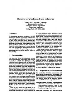
grab the information via sending queries to transmitters by disguising themselves as friendly nodes. In this paper, we only focus on the passive eavesdropping attack. We found that using directional antennas in wireless networks can significantly improve the network security in terms of reducing the eavesdropping probability in both singlehop networks and multi-hop networks. Our contributions are shown as follows. ∙ We formally establish the eavesdropping model in wireless networks. In particular, we propose the exposure region to determine whether an adversary node can eavesdrop the transmission or not. ∙ We analyze the eavesdropping attack in single-hop networks. In particular, we derive the eavesdropping probabilities of a single-hop WON and a single-hop DAWN. Moreover, we found that a DAWN has a much lower eavesdropping probability than a WON since it has a smaller exposure region. ∙ We conduct a study on the eavesdropping attack in multihop networks. Specifically, we found that using directional antennas in multi-hop wireless networks can significantly reduce the multi-hop eavesdropping probability than using omni-directional antennas. The remainder of the paper is organized as follows. Section II presents the models and the definitions. In Section III, we analyze the eavesdropping attack in single-hop networks. Section IV presents the analytical results of the eavesdropping attach in multi-hop networks. We conclude the paper in Section V. II. M ODELS AND N OTATIONS In this paper, we consider a directional antenna model that was used in previous studies [1], [9], [12]. In particular, we assume that a directional antenna gain 𝐺𝑑 is within a specific angle 𝜃, where 𝜃 is the beamwidth of the antenna, as shown in Fig. 1. The gain outside the beamwidth is assumed to be zero. More specifically, we have { 2𝜋 within 𝜃 𝜃 𝐺𝑑 = (1) 0 otherwise The antenna gain of an omni-directional antenna can be regarded as a special case in our model when the beamwidth 𝜃 = 2𝜋. Then, we have 𝐺𝑜 = 1. Note that a directional antenna generally has a beamwidth 𝜃 < 𝜋. Therefore, we have
TABLE I D IRECTIONAL C ASE AND O MNI - DIRECTIONAL C ASE directional antenna
θ
Ro
θdirection
Transmitter Receiver Adversary
Rd Fig. 1. Model
The Antenna
Fig. 2. The omnidirectional exposure region
Fig. 3. The directional exposure region
𝐺𝑑 > 𝐺𝑜 . Moreover, the narrower the beamwidth of an antenna is, the higher antenna gain it has. We denote 𝑃𝑡 the common transmission power for every node in the network and 𝛾𝑖𝑗 the channel gain from node 𝑖 to node 𝑗. Thus, the received power at node 𝑗 is 𝑃𝑡 ⋅ 𝛾𝑖𝑗 . The signalto-interference-plus-noise ratio at node 𝑗 denoted by 𝑆𝐼𝑁 𝑅 is defined to be 𝑃 ⋅𝛾 ∑ 𝑡 𝑖𝑗 (2) 𝜂 + 𝑘∕=𝑖 𝑃𝑘 ⋅ 𝛾𝑘𝑗 The transmission from node 𝑖 can be successfully received by node 𝑗 if and only if 𝑆𝐼𝑁 𝑅 ≥ 𝛽 where 𝛽 is the minimum signal to interference and noise ratio and 𝜂 is the environmental noise power level, which is assumed to be the same for all nodes. There are only one transmitter and one receiver in a singlehop network and all others nodes are passive adversary nodes, which will not transmit actively. In a multi-hop network, there are 𝑁 good nodes and 𝑀 passive adversary nodes, which will not transmit actively. Besides, only one of all the 𝑁 good nodes can transmit at a time. Thus, ∑we ignore the interference from other nodes. Then we have 𝑘∕=𝑖 𝑃𝑘 ⋅ 𝛾𝑘𝑗 = 0. 𝑃𝑡 ⋅ 𝛾𝑖𝑗 ≥𝛽 𝑆𝐼𝑁 𝑅 = 𝜂
(3)
In this paper, we only consider the large-scale path loss in the channel model [13]. Thus, the channel gain is given by 1 𝑑𝛼 𝑖𝑗
(4)
where 𝑑𝑖𝑗 denotes the distance between node 𝑖 and node 𝑗, 𝐶 = 𝜆 2 ) (𝜆 is the wavelength of the signal), 𝐺𝑡 and 𝐺𝑟 are the ( 4𝜋 antenna gains for the transmitter and the receiver, respectively, and 𝛼 is the path loss factor ( 3 ≤ 𝛼 ≤ 4) [13]. B. Eavesdropping Model In this paper, we consider two cases: (I) Omni-directional case and (II) Directional case, as shown in Table I. We use a Poisson point process to model the distribution of both the adversary nodes and the good nodes [14]. In particular, the probability 𝑝(𝑖) of finding 𝑖 nodes in an area of 𝑆 is given by: (𝜌𝑆)𝑖 −𝜌𝑆 𝑒 (5) 𝑝(𝑖) = 𝑓 (𝑖, 𝑆) = 𝑖!
Directional (II) Directional Omni Omni
where 𝜌 is the node density. If an adversary node can correctly decode the information from the transmitter, the SINR at the adversary node must satisfy the condition given in Inequality 3. Combining Inequality 3 and Eq. 4, we have 𝑑𝑖𝑗 ≤ (
A. Transmission Model
𝛾𝑖𝑗 = 𝐶 ⋅ 𝐺𝑡 ⋅ 𝐺𝑟 ⋅
Omni-directional (I) Omni Omni Omni
𝐶 ⋅ 𝑃𝑡 ⋅ 𝐺𝑡 ⋅ 𝐺𝑟 1 )𝛼 𝛽⋅𝜂
(6)
We denote the right hand side of Eq. 6 as 𝑅𝑚𝑎𝑥 which is the maximum radius within which an adversary node can correctly eavesdrop the information from the transmitter. Definition 1: (Eavesdrop Condition). An adversary node can successfully eavesdrop the information from the transmitter if and only if the adversary node is within the exposure region of the transmitter. Definition 2: (Exposure Region). The exposure region of a transmitter is an area that any adversary nodes within this area can eavesdrop the transmission from the transmitter. In particular, in the omni-directional case, a transmitter has an exposure region of a circle with radius 𝑅𝑜 , as shown in Fig. 2, which can be calculated by 𝑅𝑜 = (
𝐶 ⋅ 𝑃𝑡 ⋅ 𝐺𝑜 ⋅ 𝐺𝑜 1 )𝛼 𝛽⋅𝜂
(7)
In the directional case, a transmitter has an exposure region of a sector with angle 𝜃 and radius 𝑅𝑑 , as shown in Fig. 3, which is given by 𝑅𝑑 = (
𝐶 ⋅ 𝑃𝑡 ⋅ 𝐺𝑑 ⋅ 𝐺𝑜 1 )𝛼 𝛽⋅𝜂
(8)
Definition 3: (Eavesdropping Probability). The eavesdropping probability 𝑝(e) equals the probability that at least one adversary node falls into the exposure region 𝑆 of the transmitter. Combining the definition of the eavesdropping probability and Eq. 5, we have 𝑝(e) = 𝑝(𝑖 ≥ 1) = 1 − 𝑒−𝜌⋅𝑆
(9)
Therefore, the eavesdropping probability depends on the node density 𝜌 and the area of the exposure region 𝑆. The higher the node density is, the higher eavesdropping probability is. Besides, the larger area of the exposure region also leads to a higher eavesdropping probability. III. S ECURITY A NALYSIS ON S INGLE - HOP N ETWORKS To simplify the analysis, we define the reference node density 𝑁𝑜 , which is the average number of nodes within an exposure region of the Omni-directional case, as follows 𝑁𝑜 = 𝜌 ⋅ 𝑆𝑜 = 𝜌 ⋅ 𝜋 ⋅ 𝑅𝑜2
(10)
1.0
0.9
0.9
0.8
0.8
0.8
0.7 0.6 0.5 0.4 0.3 0.2
Omni-directional Directional
0.1 0
2
4
No
6
8
0.7 0.6 0.5 0.4 0.3 0.2
Omni-directional Directional
0.1 0
10
2
No
6
8
0.7 0.6 0.5 0.4 0.3 0.2
Omni-directional Directional
0.1 0
10
2
(a) 𝛼 = 3
4
No
6
8
0.7 0.6 0.5 0.4 0.3 0.2
0
10
1.0
0.9
0.9
0.8
0.8
0.8
0.5 0.4 0.3 0.2
Omni-directional Directional
0.1 0
2
4
N
6
8
0.6 0.5 0.4 0.3 0.2
Omni-directional Directional
0.1 10
0
2
4
o
𝑝(e) with 𝜃 =
8
0.7 0.6 0.5 0.4 0.3 0.2
Omni-directional Directional
0.1 10
0
2
4
N
o
(b) 𝛼 = 4 Fig. 4.
N
6
Fig. 5.
𝑝(e) with 𝜃 =
Fig. 6.
6
8
10
6
8
0.6 0.5 0.4 0.3 0.2
Omni-directional Directional
0.1 0
10
2
4
N
6
8
10
o
(b) 𝛼 = 4 𝜋 6
No
0.7
o
(b) 𝛼 = 4 𝜋 3
Eavesdropping probability
1.0
0.9 Eavesdropping probability
1.0
0.7
4
(a) 𝛼 = 3
0.8
0.6
2
(a) 𝛼 = 3
0.9
0.7
Omni-directional Directional
0.1
1.0
Eavesdropping probability
Eavesdropping probability
(a) 𝛼 = 3
4
Eavesdropping probability
1.0
0.9
0.8
Eavesdropping probability
1.0
0.9 Eavesdropping probability
Eavesdropping probability
1.0
(b) 𝛼 = 4
𝑝(e) with 𝜃 =
𝜋 12
𝑝(e) with 𝜃 =
Fig. 7.
𝜋 24
d
The average node within an exposure region of the Directional case (i.e., a sector with radius 𝑅𝑑 and angle 𝜃) 𝜃 1− 2 ) 𝛼 (11) 2𝜋 From Eq. 11, when 𝛼 > 2 and 𝜃 < 2𝜋, we always have 𝑆𝑑 < 𝑆𝑜 and 𝑁𝑑 < 𝑁𝑜 . We then calculate the eavesdropping probability of a WON, 𝑝𝑜 (e), and the eavesdropping probability of a DAWN, 𝑝𝑑 (e). It is shown in Fig. 4, 5, 6 and 7 that both the eavesdropping probabilities 𝑝𝑜 (e) and 𝑝𝑑 (e) increase when 𝑁𝑜 increases. This is because, when 𝑁𝑜 increases, the more adversary nodes fall into the exposure regions and lead to the higher eavesdropping probability and the less secure. Besides, it is also shown in Fig. 4, 5, 6 and 7 that at any cases, the eavesdropping probability 𝑝𝑑 (e) of a DAWN is always less than that of a WON. This is because a directional antenna has a smaller exposure region than an omni-directional antenna. Thus, using directional antennas in wireless networks can potentially reduce the eavesdropping probability and improve the security. Moreover, we also found that 𝑝𝑑 (e) decreases with the increased path loss factor 𝛼 (increasing from 3 to 4). It is shown in [13] that the path loss factor 𝛼 is generally ≥ 3 in urban outdoor environments. Therefore, using directional antennas in such environments may bring more benefits on reducing the eavesdropping probability. It is also shown in Fig. 4, 5, 6 and 7 that the narrower the antenna beamwidth 𝜃 is, the lower eavesdropping probability of a DAWN 𝑝𝑑 (e) is. Therefore, using a narrower-beam antenna can potentially reduce the eavesdropping probability and further improve the security of transmissions. 𝑁𝑑 = 𝜌 ⋅ 𝑆 𝑑 = 𝑁 𝑜 ⋅ (
IV. S ECURITY A NALYSIS ON M ULTI - HOP N ETWORKS
S
R1
Rn
R2
D
l
Fig. 8.
The Linear Network
nodes. Except them, all other nodes around them are adversary nodes. We are concerned about the minimum number of hops 𝐻, which is required to route a packet from 𝑆 to 𝐷. In fact, 𝐻 = ⌈ 𝑑𝑙 ⌉. In particular, we have the minimum number of hops of a WON, 𝐻𝑜 = ⌈ 𝑅𝑙𝑜 ⌉ and the minimum number of hops of a DAWN, 𝐻𝑑 = ⌈ 𝑅𝑙𝑑 ⌉. Note that the maximum possible length of the routing path 𝑙 is determined by the node density and the number of nodes in the networks. We assume that the number of adversary nodes 𝑀 is far greater than the number of good nodes 𝑁 (including source node 𝑆 and destination node 𝐷 as well √ as the routing nodes), i.e., 𝑀 >> 𝑁 . In fact, 𝑙 is bounded by 𝑀 𝜌 , where 𝜌 is the node density. Definition 4: Eavesdropping Probability for Multi-hop. The eavesdropping probability of a multi-hop transmission is the probability that at least one-hop transmission is eavesdropped. The eavesdropping probability of a multi-hop transmission can be calculated by 𝑝𝑚 (e) = 1 − (1 − 𝑝(e))𝐻
(12)
For a WON, 𝑝(e) = 𝑝𝑜 (e). Therefore, we have 𝑝𝑚𝑜 (e) = 1 − (1 − 𝑝𝑜 (e))𝐻𝑜
(13)
For a DAWN, 𝑝(e) = 𝑝𝑑 (e) and we have 𝑝𝑚𝑑 (e) = 1 − (1 − 𝑝𝑑 (e))𝐻𝑑
(14)
A. Linear Networks
B. Analytical Results
Fig. 8 illustrates a linear network consisting of a source node 𝑆, a destination node 𝐷 and 𝑛 routing nodes, which are all good
To illustrate the eavesdropping probability of multi-hop transmissions with varied 𝑁𝑜 , 𝜃 and 𝛼, we calculate the values of
𝑁𝑜 1 2 3 4 5 6
𝑝𝑚𝑜 (e) 0.9817 0.9975 0.9975 0.9996 0.9999 0.9999
𝑝𝑚𝑑 (e) 0.6053 0.7315 0.8002 0.8443 0.8749 0.8975
𝑁𝑜 1 2 3 4 5 6
(a) 𝛼 = 3
𝑝𝑚𝑜 (e) 0.9502 0.9817 0.9975 0.9997 0.9999 0.9999
𝑝𝑚𝑑 (e) 0.4800 0.6033 0.6778 0.7296 0.7682 0.7984
(b) 𝛼 = 4
T HE MULTI - HOP EAVESDROPPING PROBABILITY WHEN 𝜃 =
𝑝𝑚𝑜 (e) 0.9817 0.9975 0.9975 0.9996 0.9999 0.9999
𝑝𝑚𝑑 (e) 0.4433 0.5632 0.6374 0.6901 0.7301 0.7618
𝑁𝑜 1 2 3 4 5 6
(a) 𝛼 = 3
𝑝𝑚𝑜 (e) 0.9502 0.9817 0.9975 0.9997 0.9999 0.9999
𝜋 3
𝑝𝑚𝑑 (e) 0.3221 0.4229 0.4900 0.5404 0.5808 0.6142
𝑝𝑚𝑑 (e) 0.3086 0.4066 0.4722 0.5219 0.5618 0.5950
𝑁𝑜 1 2 3 4 5 6
T HE MULTI - HOP EAVESDROPPING PROBABILITY WHEN 𝜃 =
𝑝𝑚𝑜 (e) and 𝑝𝑚𝑑 (e), respectively, and list them in Tables II, III, IV and V. It is shown in Tables II, III, IV and V that with the increased node density 𝑁𝑜 , both 𝑝𝑚𝑜 (e) and 𝑝𝑚𝑑 (e) also significantly increase. But we always have 𝑝𝑚𝑑 (e) < 𝑝𝑚𝑜 (e). This is because directional antennas can significantly reduce the eavesdropping probability of multi-hop transmissions. This security improvement owe to two benefits: (i) the narrow beamwidth leads to the lower eavesdropping probability; (ii) the longer transmission range of a directional antenna leads to the fewer hops and consequently results in less eavesdropping probability of multihop transmissions. Besides, Tables II, III, IV and V also show that the narrower the beamwidth 𝜃 is, the smaller the eavesdropping probability 𝑝𝑚𝑑 (e) is. For example, 𝑝𝑚𝑑 (e) = 0.4323 with beamwidth 𝜃 = 𝜋 12 is much smaller than 𝑝𝑚𝑑 (e) = 0.6142 with beamwidth 𝜃 = 𝜋6 under the same network setting, i.e., the node density 𝑁𝑜 = 6 and the path loss factor 𝛼 = 4. Moreover, it is also shown in Table II, III, IV and V that 𝑝𝑚𝑑 (e) decreases when the path loss factor 𝛼 increases. Therefore, using directional antennas in such high path loss environments may gain more security improvement. V. C ONCLUSION In this paper, we explored using directional antennas in wireless networks to improve the network security in terms of reducing the eavesdropping probability. In particular, we analyzed the eavesdropping probability of single-hop transmissions and that of multi-hop transmissions, respectively. We found that using directional antennas in either a single-hop network or a multi-hop network can significantly reduce the eavesdropping probability. The security improvements owe to the smaller exposure region and the fewer hops due to the
𝑝𝑚𝑑 (e) 0.2064 0.2789 0.3299 0.3702 0.4036 0.4323
(b) 𝛼 = 4
T HE MULTI - HOP EAVESDROPPING PROBABILITY WHEN 𝜃 =
𝑁𝑜 1 2 3 4 5 6
𝑝𝑚𝑜 (e) 0.9817 0.9975 0.9975 0.9996 0.9999 0.9999
𝑝𝑚𝑑 (e) 0.2074 0.2802 0.3314 0.3718 0.4053 0.4341
𝑁𝑜 1 2 3 4 5 6
𝑝𝑚𝑜 (e) 0.9502 0.9817 0.9975 0.9997 0.9999 0.9999
𝜋 12
𝑝𝑚𝑑 (e) 0.1284 0.1767 0.2119 0.2404 0.2646 0.2859
(b) 𝛼 = 4 TABLE V
𝜋 6
𝑝𝑚𝑜 (e) 0.9502 0.9817 0.9975 0.9997 0.9999 0.9999
TABLE IV
(a) 𝛼 = 3
(b) 𝛼 = 4 TABLE III
𝑝𝑚𝑜 (e) 0.9817 0.9975 0.9975 0.9996 0.9999 0.9999 (a) 𝛼 = 3
TABLE II
𝑁𝑜 1 2 3 4 5 6
𝑁𝑜 1 2 3 4 5 6
T HE MULTI - HOP EAVESDROPPING PROBABILITY WHEN 𝜃 =
𝜋 24
longer transmission range. It is shown that using a narrow beam antenna can significantly improve the network security. R EFERENCES [1] S. Yi, Y. Pei, and S. Kalyanaraman, “On the capacity improvement of ad hoc wireless networks using directional antennas,” in Proc. of MobiHoc, 2003. [2] J. Zhang and S. C. Liew, “Capacity improvement of wireless ad hoc networks with directional antennae,” Mobile Computing and Communications Review, vol. 10, pp. 17 – 19, 2006. [3] H.-N. Dai, “Throughput and delay in wireless sensor networks using directional antennas,” in Proceedings of the Fifth International Conference on Intelligent Sensors, Sensor Networks and Information Processing (ISSNIP), 2009. [4] Y. B. Ko, V. Shankarkumar, and N. H. Vaidya, “Medium access control protocols using directional antennas in ad hoc networks,” in Proc. INFOCOM’2000, Tel Aviv, Israel, 2000, pp. 13 – 21. [5] A. Nasipuri, S. Ye, and R. E. Hiromoto, “A MAC protocol for mobile ad hoc networks using directional antennas,” in Proc. WCNC, 2000. [6] R. Ramanathan, “On the performance of ad hoc networks with beamforming antennas,” in Proc. of MobiHoc, 2001. [7] M. Takai, J. Martin, R. Bagrodia, and A. Ren, “Directional virtual carrier sensing for directional antennas in mobile ad hoc networks,” in Proc. MobiHoc’2002, Lausanne, Switzerland, 2002, pp. 183 – 193. [8] R. R. Choudhury, X. Yang, N. H. Vaidya, and R. Ramanathan, “Using directional antennas for medium access control in ad hoc networks,” in Proc. of ACM MobiCom, 2002. [9] T. Korakis, G. Jakllari, and L. Tassiulas, “A MAC protocol for full exploitation of directional antennas in ad-hoc wireless networks,” in Proc. MobiHoc’2003, Annapolis, Maryland, USA, 2003, pp. 98 – 107. [10] H.-N. Dai, K.-W. Ng, and M.-Y. Wu, “A Busy-Tone based MAC Scheme for Wireless Ad Hoc Networks using Directional Antennas,” in Proc. of IEEE GLOBECOM, 2007. [11] M. Anand, Z. G. Ivesy, and I. Leez, “Quantifying eavesdropping vulnerability in sensor networks,” in Proceedings of the 2nd International VLDB Workshop on Data Management for Sensor Networks, 2005. [12] H.-N. Dai, K.-W. Ng, R. C.-W. Wong, and M.-Y. Wu, “On the Capacity of Multi-Channel Wireless Networks Using Directional Antennas,” in Proc. of IEEE INFOCOM, 2008. [13] T. S. Rappaport, Wireless communications : principles and practice, 2nd ed. Upper Saddle River, N.J.: Prentice Hall PTR, 2002. [14] Y. Wang and J. J. Garcia-Luna-Aceves, “Directional collision avoidance in ad hoc networks,” Performance Evaluation Journal (Elsevier), vol. 58, pp. 215–241, 2004.