paper examines recent results in the development of toe walking on the. JenaWalker II robot. The robot is shown, while supported on a treadmill, to be capable ...
Exploring Toe Walking in a Bipedal Robot James Andrew Smith and Andre Seyfarth Lauflabor, Institute for Sports Science, Friedrich-Schiller University, Dornburger Strasse 23, 07743 Jena
Abstract. The design and development of locomotory subsystems such as legs is a key issue in the broader topic of autonomous mobile systems. Simplification of substructures, sensing, actuation and control can aid to better understand the dynamics of legged locomotion and will make the implementation of legs in engineered systems more effective. This paper examines recent results in the development of toe walking on the JenaWalker II robot. The robot is shown, while supported on a treadmill, to be capable of accelerating from 0 to over 0.6 m/s without adjustment of control parameters such as hip actuator sweep frequency or amplitude. The resulting stable motion is due to the adaptability of the passive structures incorporated into the legs. The roles of the individual muscletendon groups are examined and a potential configuration for future heel-toe trials is suggested.
1
Introduction
The design and development of locomotory subsystems is a key issue in the broader topic of autonomous mobile systems. While wheels and tracks are often the subsystems of choice for use in ground-based systems, legged and even hybrid wheeled-leg subsystems may be also be appropriate, depending on the given task and work environment. Unfortunately, all engineered legged systems developed to date are still outperformed by the multitude of efficient and effective examples found in nature. For this reason, many researchers are re-examining biological systems for inspiration and insight in the development of the next generations of legged systems. Simplification of substructures, sensing, actuation and control can aid to better understand the dynamics of legged locomotion. The RHex biped [1] is an effective running system with a control strategy that requires leg recirculation to achieve toe-clearance during leg protraction. While the underactuated JenaWalker [2] also houses compliant limbs, judicious selection and distribution of mono- and biarticular compliant elements negates the requirement for recirculation and results in more human-like walking. The JenaWalker II presented here is a continuation of this previous work and serves as a testbed to study the effect of individual substructures in the leg on the resulting gait. The spring-like properties of muscle-tendon complexes are well known and have been the topic of many biomechanics studies [3] [4]. The insights provided by biomechanicists have inspired engineers to develop robots with comparable
Body
φT
11 00 00Hip 11
Thigh
00 11
00 Knee11 00 11
0000000000 1111111111 0000000000 1111111111 0000000000 1111111111 1111111111 0000000000 0000000000 1111111111 0000000000 1111111111 0000000000 1111111111 0000000000 1111111111 0000000000 1111111111 0000000000 1111111111 0000 1111 0000 1111 0000 1111 0000 1111 0000 1111 0000 1111 0000 1111 0000 1111 0000 1111 0000 1111 0000 1111 0000 1111 0000 1111 0000 1111 0000 1111 0000000000 1111111111 0000 1111 0000000000 1111111111 0000 1111 0000000000 1111111111 0000 1111 0000000000 1111111111 0000 1111 0000000000 1111111111 0000 1111 0000000000 1111111111 0000 1111 0000000000 1111111111 0000 1111 0000000000 1111111111 0000 1111 0000000000 1111111111 0000 1111 0000000000 1111111111 0000000000 1111111111 0000 1111 0000000000 1111111111 0000 1111 0000000000 1111111111 0000 1111 0000000000 1111111111 0000 1111 0000000000 1111111111 0000 1111 0000000000 1111111111 0000 1111 0000000000 1111111111 0000 1111 0000000000 1111111111 0000 1111 0000000000 1111111111 0000 1111 0000000 1111111 0000 1111 0000000000 1111111111 0000 1111 0000000 1111111 0000 1111 0000 1111 0000000 1111111 0000 1111 0000 1111 0000000 1111111 0000 1111 0000 1111 0000000 1111111 0000 1111 0000 1111 0000000 1111111 0000 1111 0000 1111 0000000 1111111 0000 1111 0000 1111 0000000 1111111 0000 1111 0000 1111 0000000 1111111 0000 1111 0000 1111 0000000 1111111 0000 1111 0000 1111 0000000 1111111 0000 1111 0000 1111 0000000 1111111 0000 1111 0000 1111 0000000 1111111 0000 1111 0000 1111 0000000 1111111 0000 1111 0000 1111 0000000 1111111 0000 1111 0000 1111 0000000 1111111 0000 1111 0000000000 1111111111 0000000000 1111111111 0000000000 1111111111 0000000000 1111111111 00000000001111111111 1111111111 0000000000 1111111111 0000000000 1111111111 0000000000 00000000001111111111 1111111111 0000000000 1111111111 0000000000 1111111111 0000000000 00000000001111111111 1111111111 0000000000 1111111111 0000000000 1111111111 0000000000 0000000000 1111111111 0000000000 1111111111 00000000001111111111 1111111111 0000000000 00000000000000000000000000000000000000000000000 11111111111111111111111111111111111111111111111 00000000000000000000000000000000000000000000000 11111111111111111111111111111111111111111111111 00000000000000000000000000000000000000000000000 11111111111111111111111111111111111111111111111 11111111111111111111111111111111111111111111111 00000000000000000000000000000000000000000000000
0.185 m
RF
φK
TA
Shank
Foot
11111111111111111111111111111 00000000000000000000000000000 00000000000000000000000000000 11111111111111111111111111111
(b) Nomenclature
GA
0.035 m
111 000 000 111 000Ankle 111
0.085 m
φA
(a) Robot
"Sitting" Configuration
0.175 m
0.045 m
"Standing" Configuration
(c) Geometrical Parameters
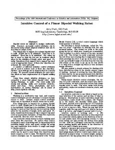
Fig. 1. The JenaWalker II robot on a treadmill (left), the leg link and joint nomenclature (middle), and the geometrical parameters and layout (right) of the gastrocnemius (GA), tibialis anterior (TA) and rectus femoris (RF) elements.
characteristics to walking and running animals [5]. While there has been a tendency to model bipedal walking as stiff (i.e. the inverted pendulum) [3] [6] and modeling bipedal running as compliant (i.e. the spring-loaded inverted pendulum) [7], it has become increasingly evident that both gaits utilize compliant elements [8] [9]. While it is the objective of the authors’ ongoing work to study both walking and running, the former is the focus of this paper. Of the walking gaits, the heeltoe walking mode is standard for most humans but is sometimes replaced by the “primitive” [10] toe walking gait in small children, in ballet dancers and in people with certain neuromuscular diseases [11]. It is often caused by a shortening of the Achilles tendon, resulting in an equinus ankle configuration. The current configuration of the JenaWalker II, shown in Fig. 1a., is relatively simple and it follows that the resulting gaits will also be relatively simple, making the study of toe-walking appropriate at this early stage. One of the strong motivating factors behind the study of toe-walking was to reduce the effect of impact at touchdown found during heel-toe or flat-footed ambulation. In flat-footed walking both the heel and toe of the foot contact the ground at approximately the same time, while in heel-toe walking the heel contacts first, followed by a shift to the ball of the foot. In both cases the impact phase is characterized by the leg’s effective configuration as a two-segment system, thus requiring that the knee flex during stance for the leg to display any compliance. Toe walking, on the other hand, allows the leg to operate as a three segment system from the moment of impact, allowing either knee or ankle flexure to result in compliant leg activity. As the control and leg parameters used in the trials presented here (as well as in preliminary trials) generally resulted in straight-knee stance phases, the availability of ankle flexure guarantees that the leg will demonstrate at least some overall compliance.
2
Methods
The Jena Walker II, a bipedal robot, shown in Fig. 1a., consists of two modular legs. Each leg consists of rigid segments, joint modules and easily replaceable springs spanning hip, knee and ankle joints. The robot has a 0.45 m hip height and weighs about 1.78 kg, of which approximately two-thirds are suspended by an elastic rope; other geometrical and mass parameters are listed in Table 1. The foot consists of a prosthetic foot (SACH child foot, Otto Bock; slightly modified to fit the robot ankle joint and mechanical cabling). While four major leg muscle-tendon groups are usually represented in the robot by compliant structures: tibialis anterior (TA), gastrocnemius (GA), rectus femoris (RF) and biceps femoris (BF), only three (TA, GA and RF) are used in the results presented here, shown in Fig. 1c. Except for the TA, all muscle-tendon groups span two joints leading to an inter-joint coupling within the leg. Spring constant and spring length values are given in Table 2. The robot is constrained to the sagittal plane on a treadmill (Schmidt Sportsworld) via an overhead boom. In the standing configuration (see Fig. 1c.) the pivot of the overhead boom is about 1 m from the bottom of the robot’s foot. Actuation is provided by two Maxon RE-Max 29 motors with 128:1 GP-26 B gearheads. Control is provided by a custom-programmed robot control unit. Motor power is also supplied to the robot by the robot control unit and is limited to a maximum of 24 Volts DC and about 2.5 Amperes. The robot’s hip actuators were set to oscillate out-of-phase with a peak-topeak amplitude of 49◦ , an inclination bias of 7◦ and a period of 0.66 s. The length of the gastrocnemius foot extensor cable of each leg was shortened to give the ankle an approximate 130◦ extension value. The RF and TA muscletendon groups are represented by linear metal extension springs (Associated Spring SPEC 0E0360-0411500M and 0E0120-0181370S, respectively). The spring constants and rest lengths, as well as the spring lengths in two different leg configurations are given in Table 2. The two leg configurations are shown in Fig. 1c. Table 1. Robot and Simulation Model Geometry and Mass Parameters Parameter
JenaWalker II Robot Total Mass (free) 1.780 kg Total Mass (suspended) 0.590 kg Joint Mass 0.060 kg Thigh Link Mass 0.010 kg Shank Link Mass 0.010 kg Foot Mass 0.090 kg Thigh Link Length 0.185 m Shank Link Length 0.175 m Foot Height 0.045 m Foot Length 0.120 m
(a) Pre-touchdown
(b) Touchdown
(c) Ankle flexion
(d) Ankle extension
(e) Pre-Liftoff
(f) Liftoff
Fig. 2. Still frames from video taken while the robot walked at 0.682 m/s. Table 2. Robot leg spring parameters. Refer to Fig. 1c for an illustration of the “sit” and “stand” leg configurations. Muscle
Rectus Femoris (RF) Tibialis Anterior (TA) Gastrocnemius (GA)
3
Type
Metal Ext. Spring Metal Ext. Spring Tensioned Cable
Spring Constant [N/m] 1030 320 n/a
Rest Length [m] 0.040 0.038 n/a
Sit Length [m] 0.040 0.065 n/a
Stand Length [m] 0.050 0.065 n/a
Results
The robot was made to toe walk at various treadmill-induced speeds (0.243, 0.366, 0.489 and 0.682 m/s) using fixed hip control and leg compliance characteristics (i.e. a hip frequency of 1.5 Hz and compliance values listed in Table 2). At all speeds induced by the treadmill, there is a match between the hip oscillation frequency and the resulting stride frequency. The stance phase was also found to be over 50% of the gait cycle in all four trials, matching an intuitive, but not formal, definition for walking. The three individual three leg joints (hip, knee and ankle) demonstrate the following noteworthy characteristics. The hip angle tracings of Fig. 3 illustrate that thigh retraction and protraction occur in both the leg stance and leg flight stages of walking. In fact, the thigh begins its protraction during the middle of
Stance
Hip Angle (deg)
160
Flight
Stance
Knee Angle (deg)
140 180 160
Flight
140 120 160 140 Stance
Flight
120 100 0
20
40 60 % Gait Cycle
80
Joint Angles for Walking at 0.682 m/s
Ankle Angle (deg)
Ankle Angle (deg)
Knee Angle (deg)
Hip Angle (deg)
Joint Angles for Walking at 0.243 m/s 180
100
180 160
Stance
Flight
140 180 160
Stance
Flight
140 120 160 140 Stance
Flight
120 100 0
20
40 60 % Gait Cycle
80
100
(a) Slowest Trial (b) Fastest Trial Fig. 3. Leg joint angles for walking at lowest and highest speeds reported. Positive slopes refer to joint extension, and negative slopes to flexion. Retraction occurs with positive hip joint slope and protraction with negative hip joint slope.
the stance phase, as seen by its negative slope. The knee also shows a change in behaviour at the midpoint of stance, where it changes to flexion from its original extended (i.e. straight) joint configuration. Maximum knee flexion occurs at, or slightly after, the leg liftoff condition. Maximum knee extension, which leads to the straight knee behaviour, begins approximately halfway through the flight phase. The ankle joint exhibits a combined flexion-extension movement during the first portion of stance as a response to the impact between the foot and the treadmill belt. In addition, some flexion continues until the foot liftoff condition. Since the hip frequency remains fixed, the only possible strategy for the biped to match the treadmill speed is by increasing its step length. This is made possible by passive increases in hip, knee and ankle amplitudes, as is apparent in a comparison of Figs. 3a and 3b. This is due to the inclusion of compliant elements in the leg, such as a plastic coupler between the hip gearhead motor and the hip joint, as well as the explicit mechanical springs distributed throughout the leg.
4
Discussion
Steady toe walking was found to be achievable from 0 m/s to almost 0.7 m/s. The resulting gaits maintained a stride frequency of 1.5 Hz at all speeds. While neither the characteristics of the extension springs, nor the control action of the hip motors changed during the trials, the differences in the tracings of the joint angles illustrate the presence of passive dynamic adaptation of the legs to increases in treadmill speed. The results are speed-dependent knee and ankle
joint movement which are similar to human walking (e.g. maximum knee flexion at end of stance), with an increase in variability as speed increases. Toe walking results in a compliant leg, with ankle flexion and extension occuring immediately after impact, even if the knee joint does not move. The flexion of the ankle results in an extension of the relatively stiff GA. Given the importance of GA compliance at higher speeds [12], the demonstration of even minimal compliance in these results is welcome. However, the GA cable’s usefulness as a spring is limited as it cannot stretch more than a small amount. This limitation became apparent when the treadmill speed was increased beyond 0.7 m/s, resulting in the failure of the GA cable of the right leg. The failure occurred immediately after touchdown, when the ankle flexion (as shown in the graphs of Fig. 3) and GA cable extension occur. This result indicates that a cable or spring which can support a larger stretch length will be required. While ankle flexion and extension immediately after touchdown and knee flexion at the end of stance phase are qualitatively similar to human toe walking results [13] [10], other aspects of the JenaWalker II results are not. The doublehumped ankle angle pattern (reminiscent of the COM pattern observed by Farley during walking [14]) found by both Perry [10] and Jaeger [13] to occur after the impact management phase is essentially absent in the robot results. This is perhaps a further indication of the potential importance for compliance in structures such as the GA and soleus (SOL) muscle-tendon groups. Interestingly, Perry’s toe walking trials showed reduction in knee flexion as compared to heel-toe walking in the late stance and swing phases. While the JenaWalker II also shows limited knee flexion, it is most evident in the first half of the stance phase of the JenaWalker II trials, see Figs. 2a - 2d, as well as Fig. 3, making the leg look particularly stiff. In addition, this gait seems to rely on the mechanical joint limit built into the knee. Future work will examine configurations of the robot which do not rely on these mechanical limits to develop stable walking or running. The toe-walking trials have allowed an examination of the roles of the three muscle-tendon groups included in the JenaWalker II. The GA is shown to absorb a portion of the impact at touchdown. However, there isn’t a rapid extension of the ankle joint that one would associate with unloading of the GA. The GA is, thus, essentially limited to synchronization of the flexion and extension of the knee and ankle joints, as observed in human running results [9]; therefore negating the possibility of out-of-phase joint action usually seen in human walking. The TA, given that it contracts at the moment of foot impact, acts simply as an antagonist to the GA. The role of the RF, as seen here, is to prepare the leg for landing. It is loaded during the late stance phase when both the hip and knee flex and contracts during mid to late flight. Because it is unopposed by an antagonist (e.g. the biceps femoris) the knee, and therefore the leg, is placed in a straight configuration. The introduction of a BF mechanism would seem appropriate to develop a slightly flexed (crouched) knee configuration prior to stance. This would enable the knee to act in a compliant fashion, making heel-toe walking more feasible.
5
Conclusions
The introduction of toe walking to the robot enables it to walk with a compliant gait even though the knee does not participate in overall leg compliance. The leg compliance is due to the compliant action about the ankle joint, in spite of the fact that the gastrocnemius cable is relatively stiff. This toe walking leg configuration is shown to enable the biped to walk at over 0.6 m/s while also reducing the effect of impacts previously seen in flat-footed or heel-toe walking. While overall leg compliance is demonstrated it is not identical to results observed in human trials, most probably due to the minimal number of muscle-tendon group structures, as well as the lack of sufficient gastrocnemius compliance. The rectus femoris would seem to be responsible for the straight-knee stance, making the future use of an opposing biceps femoris a possibility for the development of a compliant configuration suited to the more common heel-toe walking.
Acknowledgments The authors are supported by the Thuringian HWP and the German DFG.
References 1. N. Neville, M. Buehler, and I. Sharf. A bipedal running robot with one actuator per leg. In IEEE Int. Conf. Robotics and Automation, Orlando, USA, May 2006. 2. F. Iida, Y. Minekawa, J. Rummel, and A. Seyfarth. Intelligent Autonomous Systems, chapter Toward a Human-Like Biped Robot with Compliant Legs, pages 820–827. Number 9. IOS Press, 2006. 3. R. McNeill Alexander. Three uses for springs in legged locomotion. International Journal of Robotics Research, 9(2), 1990. 4. T. A. McMahon. Muscles, reflexes, and locomotion. Princeton University Press, Princeton, N.J., USA, 1984. 5. M. Raibert. Legged Robots That Balance. The MIT Press, Cambridge, USA, 1986. 6. T. McGeer. Passive bipedal running. Technical report, Simon Fraser University, Centre For Systems Science, Burnaby, B.C., Canada, 1989. 7. R. Blickhan. The spring-mass model for running and hopping. J. Biomech., 22:1217–1227, 1989. 8. H. Geyer, A. Seyfarth, and R. Blickhan. Compliant leg behaviour explains basic dynamics of walking and running. Proc. R. Soc. B, 273(1603):2861 – 2867, 2006. 9. S. Lipfert and A. Seyfarth. Elastic legs in human walking. J. Biomech., 40(S2):S385, 2007. 10. J. Perry, J. M. Burnfield, J. K. Gronley, and Mulroy S. J. Toe walking: muscular demands at the ankle and knee. Arch Phys Med Rehabil, 84(1):7–16, Jan. 2003. 11. E. P. Schwentker. Toe walking. Online publication, eMedicine.com, July 2004. 12. M. Ishikawa, P. V. Komi, M. J. Grey, V. Lepola, and G.-P. Bruggemann. Muscletendon interaction and elastic energy usage in human walking. J. Appl. Physiol, 99:603 – 608, 2005. 13. C. Jaeger. Einfluss der Fusshaltung und Laufgeschwindigkeit auf die Biomechanik des Gehens. Diploma thesis, FSU-Jena, Jena, Germany, October 2006. 14. C. T. Farley. Determinants of the center of mass trajectory in human walking and running. The Journal of Experimental Biology, 201:2935 – 2944, 1998.