Progress In Electromagnetics Research, PIER 99, 89–108, 2009
EXTENDED EXACT TRANSFER FUNCTION ALGORITHM FOR BISTATIC SAR OF TRANSLATIONAL INVARIANT CASE J. P. Sun and S. Y. Mao School of Electronic and Information Engineering Beihang University Beijing, China G. H. Wang School of Electrical and Electronic Engineering Nanyang Technological University Singapore W. Hong National Key Lab of MW Imaging Technology Institute of Electronics, CAS Beijing, China
Abstract—This paper presents an Extended Exact Transfer Function (EETF) algorithm for Bistatic Synthetic Aperture Radar (BiSAR) imaging of a Translational Invariant (TI) case. This algorithm adopts directly the 2D transfer function of monostatic SAR (MoSAR), instead of deriving a new one, by converting the BiSAR into an equivalent MoSAR. A new azimuth phase compensation function is constructed through exploiting this equivalency. Geometry distortion correction for BiSAR imaging result is considered in the proposed algorithm. In addition, the applying condition of the algorithm is also discussed. One desirable property of the proposed algorithm is that the computing flow and efficiency are the same as ETF algorithm for MoSAR. The effectiveness is validated by point target simulations with Tandem and forward-looking configuration.
Corresponding author: G. H. Wang (
[email protected]).
90
Sun et al.
1. INTRODUCTION Bistatic Synthetic Aperture Radar (BiSAR) obtains more flexible imaging geometry configuration than conventional monostatic SAR (MoSAR) because of spatial separation of transmitter and receiver. Bistatic geometry can possibly contribute to various SAR functions such as passive imaging and reconnaissance, forward-looking imaging, interferometric imaging, moving target indication, etc. [1–4]. So far, some research institutes have carried out experiments [5–9]. The imaging algorithm for BiSAR is different from the algorithms for Mo SAR due to the separation of transmitter and receiver. Timedomain Back-Projection (BP) algorithm is the most popular one in current practical applications [4, 5, 10] despite its inefficiency in computation. Literature [11] presents an approximate model in 2D frequency domain for the echoes of BiSAR with an arbitrary geometry configuration. Based on the approximate formula, Omega-K algorithm and 2D Inverse Scaled Fast Furior Transform (ISFFT) algorithm are proposed under different approximate conditions [12, 13]. In [14] and [15], other two Omega-K algorithms are proposed, respectively. Besides the algorithms mentioned above, there are some other BiSAR imaging algorithms, for example, equivalent monostatic imaging algorithm [16], Non-Linear Chirp Scaling Algorithm (NLCSA) [17], ‘NuSAR’ method [18, 19], Polar Formation Algorithm (PFA) [20], and the methods based on two-dimensional spectrum model [21, 22], etc.. The imaging algorithm for bistatic SAR is still in its infancy compared with the conventional imaging algorithm for MoSAR [4]. In BiSAR with Translational Invariant (TI) configuration, the transmitter is moving at the same direction and velocity as the receiver. The raw data point responses are sufficiently azimuth invariant within a processing block. TI imaging configuration, as used in many experiments of BiSAR at present [5–7], is suitable to produce large area stripmap images. Most of the algorithms mentioned above can be applied in TI configuration, however, with the shortcoming of large computational load. For example, the Stolt interpolation [12, 14, 15] or computation of transfer function by numerical method [18, 19] is required beforehand. With respect to TI configuration, an equivalent monostatic imaging algorithm is proposed firstly in [16]. It firstly transforms the BiSAR echo data into equivalent MoSAR data by SMILE transformation and then processes the transformed data through standard MoSAR imaging algorithm. Although the algorithm only aims at simple Tandem configuration, it can process data of BiSAR with only a few modifications on existing imaging processor for MoSAR. Thus, this algorithm has certain value in practice.
Progress In Electromagnetics Research, PIER 99, 2009
91
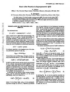
This paper presents a new equivalent monostatic imaging algorithm for BiSAR with TI configuration. The ‘equivalent’ here means that we do not derive a new 2D transfer function for BiSAR; instead, we use the given 2D transfer function of MoSAR directly. By introducing a virtual point target in the equivalent monostatic geometry, the phase history of BiSAR echo is approximated. Then we can get the new azimuth phase compensation function through a mapping between slant range and ground range determined by the bistatic imaging geometry; thus the focusing imaging for BiSAR of TI configuration along azimuth can be fulfilled. Meanwhile, the geometry distortion correction is also considered in the imaging process, which facilitates the post processing and BiSAR image understanding. As the imaging processing based on accurate 2D transfer function in MoSAR is named as Exact Transform Function (ETF) algorithm, we denote the imaging algorithm for BiSAR presented in this paper as Extended ETF (EETF) algorithm. The new algorithm maintains the advantages of conventional ETF algorithm in monostatic SAR, such as simple computing flow and high efficiency. The algorithm can be easily applied to BiSAR imaging with most TI configurations on existing MoSAR imaging processor. The reminder of this paper is organized as follows. In Section 2, the equivalent monostatic imaging model for BiSAR system with TI configuration will be derived by investigating phase history of BiSAR echo. In Section 3, the EETF algorithm for BiSAR imaging will be developed by introducing virtual point targets. Furthermore, the applying condition of the algorithm will also be discussed. In Section 4, we will validate the effectiveness of this algorithm by point target simulations for two typical TI BiSAR cases. The conclusions will be finally summarized in Section 5. 2. EQUIVALENT MONOSTATIC IMAGING MODEL FOR BISAR In this section, we will develop a new method that transforms the bistatic configuration to an equivalent monostatic one. The equivalence is achieved by making the constant term, the linear term and the quadratic term of the true bistatic range history equal to their counterparts of an equivalent monostatic range history. The imaging geometry for stripmap mode BiSAR of TI configuration is shown in Fig. 1. Transmitter S1 and receiver S2 are carried on moving platforms with same velocity of v, and altitudes of h1 and h2 , respectively. Let t be the azimuth time. When t = 0, the instant slant range between the swath centre O and antenna phase
92
Sun et al.
vE
t =0
ϕE v
t =0
S1
t =0
ϕ1 h1
S2 v
ϕ2 R02
R01
ϕ% E
R0E
h2
O
x O (0, 0) P(0, ∆y )
∆r y
Figure 1. Imaging geometry for stripmap mode BiSAR with TI configuration.
∆rE P%
E
PE r
Figure 2. Imaging geometry of equivalent monostatic SAR.
center is R01 for transmitter and R02 for receiver. The squint angle, defined as the angle between the radar Light of Sight (LOS) and the flying direction, is ϕ1 for transmitter and ϕ2 for receiver, respectively. According to the geometry shown in Fig. 1, the range history of signal from S1 to S2 via centre O can be written as p R(t) = (R01 sin ϕ1 )2 + (vt − R01 cos ϕ1 )2 p + (R02 sin ϕ2 )2 + (vt − R02 cos ϕ2 )2 . (1) Suppose that the synthetic aperture length is far less than the distance between radar and target area, then we can apply Taylor expansion to (1) as bellow µ ¶ 1 2 sin2 ϕ1 sin2 ϕ2 2 R(t) ≈ (R01 +R02 )−v(cos ϕ1 +cos ϕ2 )t+ v + t 2 R01 R02 µ ¶ 1 3 sin2 ϕ1 cos ϕ1 sin2 ϕ2 cos ϕ2 3 + v + t ··· . (2) 2 2 2 R01 R02 To obtain equivalent monostatic model for BiSAR, the received BiSAR echo signal should be transformed into signal of MoSAR correspondingly. As this transformation is performed in echo domain, we consider the equivalent imaging geometry in the data collection plane. The equivalent imaging geometry is shown in Fig. 2, where vE , ϕE , R0E are equivalent platform velocity, equivalent squint angle and equivalent slant range, respectively. According to Fig. 2, for equivalent monostatic system, the range history of echo signal returned from central point O is p RE (t) = 2 (R0E sin ϕE )2 + (vE t − R0E cos ϕE )2 3 sin2 ϕ cos ϕ v 2 sin2 ϕE 2 vE E E 3 ≈ 2R0E −2vE cos ϕE + E t +· · · . (3) t + 2 R0E R0E
Progress In Electromagnetics Research, PIER 99, 2009
93
Generally, parameters in the equivalent system should be chosen to make RE (t) as close as possible to BiSAR range history in (1). Thus, we make the constant term, linear term (Doppler centroid) and quadratic term (Doppler rate) in (2) to be equal to the corresponding terms in (3). This is because these terms mainly affect focusing. Consequently, a system of equations with three unknowns, say, vE , ϕE and R0E , can be obtained. The solution of the system of equations can be achieved and the parameters of equivalent model are R01 + R02 sµ2 ¶ µ ¶ R01 v R02 2 2 sin ϕ1 + 1+ sin ϕ2 +2 cos ϕ1 cos ϕ2 (4) vE = 1+ 2 R01 R02 µ ¶ v (cos ϕ1 + cos ϕ2 ) −1 ϕE = cos · . vE 2
R0E =
With the equivalent monostatic model determined by (4), fully focused image result can be achieved for point target at the position of swath centre by ignoring the equivalent range error from above quadratic terms. We also examine the effectiveness of focusing for point targets at other positions in the swath. The x-y coordinate of ground scene is shown is Fig. 1. For point target P (0, ∆y), the corresponding range history can be written as R(t; ∆y) = R1 (t; ∆y) + R2 (t; ∆y) q R1 (t; ∆y) = (Y01 + ∆y)2 + h21 + (vt − R01 cos ϕ1 )2 q R2 (t; ∆y) = (Y02 + ∆y)2 + h22 + (vt − R02 cos ϕ2 )2 q q Y01 = (R01 sin ϕ1 )2 − h21 , Y02 = (R02 sin ϕ2 )2 − h22 .
(5)
Then, the range at the moment of t = 0 is R(0; ∆y) = R1 (0; ∆y) + R2 (0; ∆y) q q 2 +∆y 2 +2Y ∆y+ R2 +∆y 2 +2Y ∆y . = R01 01 02 02
(6)
At this very moment, the difference between this range and the twoway slant range in the equivalent model determined by (4) is 2∆r = R(0; ∆y) − 2R0E = R(0; ∆y) − (R01 + R02 ) q q 2 2 +∆y 2 +2Y ∆y−(R +R ) . (7) 2 = R01 +∆y +2Y01 ∆y+ R02 02 01 02
94
Sun et al.
Generally, the width of imaging region is far less than the range from the region to radar. That means ∆y