Extending an XML environment definition language for spoken dialogue and web-based interfaces Pablo A. Haya EPS-UAM Madrid, Spain +34 91 497 22 67 Pablo.Haya @uam.es
Germán Montoro EPS-UAM Madrid, Spain +34 91 497 22 10 German.Montoro @uam.es
Xavier Alamán EPS-UAM Madrid, Spain +34 91 497 22 50 Xavier.Alaman @uam.es
ABSTRACT
In this work we describe how we employ XML-compliant languages to define an intelligent environment. This language represents the environment, its entities and their relationships. The XML environment definition is transformed in a middleware layer that provides interaction with the environment. Additionally, this XML definition language has been extended to support two different user interfaces. A spoken dialogue interface is created by means of specific linguistic information. GUI interaction information is converted in a web-based interface. Keywords
Interface design, XML, UIDL, intelligent environments, spoken dialogues, web interfaces. INTRODUCTION
Within the ubiquitous computing [13] research area it is necessary the study of the design of transparent user interfaces for the interaction with intelligent environments [4]. These interfaces provide new ways of interaction [14], adapt to the users and the environment and offer new challenges to interface designers [11]. Intelligent environment interfaces can range from a GUI mobile-interface (for instance a web-based interface, accessible from a computer or a PDA) to a higher-level interface (such as a spoken dialogue or a gesture-based interface). Given the dynamic characteristics of intelligent environments, these interfaces have to be easily configurable and adaptable [7, 10] and have to provide standard methods of definition and configuration. Bearing in mind these conditions we have developed an XML-compliant language that allows to define the characteristics of an intelligent environment. Furthermore, we have added interface information to the language, creating a user interface description language (UIDL) that permits to automatically create a web-based interface and a spoken dialogue interface based on the environment information.
Rubén Cabello EPS-UAM Madrid, Spain +34 91 497 22 68 Ruben.Cabello @uam.es
Javier Martínez EPS-UAM Madrid, Spain +34 91 497 22 54 Javier.Martinez @uam.es
Here we present the main ideas of our XML-based language that defines the intelligent environment and these two interfaces. Next sections are organized as follows: first, we give brief overview of the user interface definition languages; next, we describe the environment representation through our XML language; after that, we present the definition of the web-based and spoken dialogue interfaces; next we explain the implemented environment and, finally, we present the conclusions. USER INTERFACE DEFINITION LANGUAGES
XML stands as a solution for the standardization of the interoperability between applications. Therefore, new XML-compliant languages are employed to define user interfaces. These are the XML-compliant user interface definition languages (XML-UIDL). They have the advantage of being transparent to different interface technologies and providing a homogeneous resource for heterogeneous ways of interaction [1]. According to [12] these XML languages for interface representation must be applicable to any target, any delivery context, personalizable, flexible and extensible. On the other hand, they should separate the interface elements from their presentation. The user interface elements must be explicitly represented and in a format that can be rendered in any delivered context. The presentation information should be provided in an abstract form that is target and delivery-context independent. Two representative languages are: •
UIML [2], an XML-compliant language which permits the creation of user interfaces for any device, any target language and any operating system. It describes the appearance of the interface, the user interaction with the interface and how it is connected to the application logic.
•
XIML [9], an XML-based "interface representation language for universal support of functionality across the entire lifecycle of a user interface: design, development, operation, management, organization, and evaluation".
Other languages are XUL [6], that allows to build easily customizable graphical user interfaces for multiple
platforms. AAIML [15], an XML-based language used to communicate an abstract user interface definition for a service or device to a user's personal device. And XAML [8], the Microsoft XML based language employed for visual interfaces to define a layout of text, images and controls. XML ENVIRONMENT DEFINITION
The physical environment is represented in a document, where each environment entity is described using an XML format. Entities are not only formed by the physical devices presented in the environment, but also by software applications, people definition or abstract concepts. This XML representation also allows to describe the relationships between the environment entities. These relationships define the distribution of the environment (buildings, rooms, etc.), aggregations of people (by workgroups, range, etc.) and dynamic links between entities (the favorite paintings of a person, the output speaker for a music source, etc.). The XML information is processed by a parser and transformed in a middleware layer, which will act as an interaction layer between the user interfaces and the physical environment. The middleware implementation lies on a global data structure, called blackboard [5]. This blackboard is a model of the world, where all the prominent information related to the environment is stored. The blackboard provides an asynchronous communication mechanism. Senders publish environment information in the blackboard, and receivers can be subscribed to these changes or pull them directly from the blackboard. This mechanism permits a looselycoupled interaction among senders and receivers given that it is not needed that either both of them are active at the same time or they know each other. Therefore, the blackboard allows to communicate environment changes, finding available devices and revealing if a device has been added or removed.
Every entity node has assigned a name. This is a unique alphanumerical string. This way, the node name univocally represents the entity. Moreover, entity nodes hold extra information that indicates the entity type (an entity can be a device, a person, a room, etc.). The entity layer is composed as follows. Every entity has a collection of properties. Entities of the same type inherit a set of common properties, which defines their specific characteristics. Besides, the entities can define new common properties, called parameters, which represent custom information for the entity. The composition of each environment entity is reflected in the blackboard as a tree structure. The tree root is one of the nodes of the previously described relationship graph. This node has a set of child nodes that defines its properties and parameters. A property node constitutes an intrinsic and universally accepted feature of the entity. Properties have a name and a value. Thus, two properties that belong to the same entity must have distinct names. Values are leaf nodes that store literal values which can be of type string, integer or real. Besides, the changes on the values of the properties that represent physical variables are reflected in the real world. Thus, when an application or an interface needs to get or to change the physical state of a device, it only has to access to the right node in the graph and get or change its value. Parameter nodes represent a set of specific features defined by an application or a group of applications, and allow to customize the entity model. Parameters hang of a parameter set node (aka paramSet node). Each group of applications can define its own paramSet independently of the rest. Parameters, like properties, are name-value pairs. Nevertheless, they can be associated not only to an entity but also to a property. This mechanism provides fine-grain parameterisation.
Environment representation
The environment information stored in this blackboard can be viewed as a two-layered structure. On the one hand, a relationship layer has information about the relations between entities. On the other hand, an entity layer stores information about each particular entity. The relationship layer is a non-directed graph where each node is an entity. Each entity node represents relevant environment information such as physical devices, software applications, occupants or abstract concepts. Arcs between entity nodes denote some kind of relationship (composition, aggregation, association, etc.). For example, the location of a person is modelled as an arc between that person and the room where s/he is located. Given that we employ non-directed arcs, reciprocal relations are also modelled. Therefore, each room has a relationship with every one of its occupants.
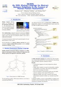
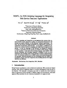
Figure 1. Blackboard: entities and their relationships So, combining these two layers, the resulting blackboard structure can be seen like a graph of entities, where each entity is described as tree of properties and parameters. Figure 1 depicts a schematic blackboard graph. It contains five entity nodes, four property nodes and two paramSet nodes with one parameter each. Entities are within a blank circle, with their name and type (for instance, Andrew and person). Double-arrow lines indicate a bidirectional
relationship. Shadowed solid circles represent property nodes (for instance, e-mail), blank dashed circles represent paramSets (for instance, Jeoffrey) and shadowed dashed circles represent parameters (for instance, image). Finally, rectangles hold the node value (for instance,
[email protected]). This structure allows to organize the environment information using several abstraction levels. The deepest nodes represent more concrete properties, while the upper nodes in the hierarchy reflect structural relationships among entities. Name Space
An entity node can be indexed by its name. Besides, a node can be located, starting from any entity node and following the relationship path. This is called the node path. It is composed by a list of tokens separated by the slash character. Their order is determined as follows: the first token of the path is the word “name”, the second one must be the entity name and the next tokens come as the result of concatenating the names of all the intermediate nodes until the target node. For instance, in the example showed in the figure 1, the lamp_1 status path is /name/lamp_1/status. In addition, wildcards can be used to substitute one or several tokens. This allows referencing several nodes at the same time. For example, based on the figure 1, /name/dave/* references all the properties, paramSets and related entities of the entity Dave. As a result it gets the following list: the e-mail and busy property nodes and the Lab_407 entity node. Another two naming mechanisms are provided to improve the use of wildcards: •
•
Predefined hierarchy. This mechanism restricts the nodes that compose a path. It specifies how to go through the graph. To do this, each hierarchy defines a sequence of types of entities. For example, the first type of entity must be a room, the second one a device, etc… Therefore, when a wildcard is used, only the nodes that match with the expected type will be substituted. These hierarchies are called predefined because they are hardwired. Following with the example of the figure 1, the path /roomdevice/lab407/*/props/status is interpreted as follows: the initial token identifies the hierarchy roomdevice. This hierarchy establishes that the first type of entity must be a room followed by a device. The other nodes remain unrestricted. Therefore, this path references the value of the status of all the devices located in lab407. Typed hierarchy. This is a particular case of the previous mechanism. By default, there will be as many hierarchies as types of entities. The initial token of these hierarchies is the type of entity. For example, in the figure 1 there are three default hierarchies: person, room and device, so that /person/*/mail retrieves the e-mails from everybody.
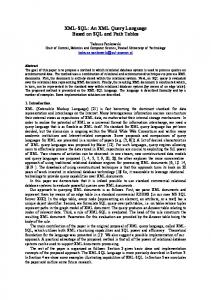
value value value value ..... ..... value value ..... value value ..... ...... ….. Figure 2. XML template for an entity Interaction with the blackboard
Interfaces do not interact directly with the environment physical entities but they only have access to the middleware information. So, the implementation details of an entity are hidden to the applications and these only have to use the same standard communication rules for any entity of the environment. The middleware provides a set of operations that allows to retrieve the information stored in blackboard, make changes on the values of the properties and add or remove an entity or a relationship. To access or change the blackboard information, applications and interfaces employ a simple communication mechanism through the HTTP protocol, by means of XML-compliant messages. Figure 2 shows an XML representation of a generic entity obtained from the blackboard. Thereby, the initial backboard structure can be generated from a set of XML files that store the environment configuration. As we have seen in this section it is simple and standard to describe the environment, retrieve the state of its entities or
change it. The XML-compliant definition language serves as a standard tool to specify the characteristics of the environment. Once created, to get or change the physical state of an entity of the environment or add or remove new entities is also possible by means of standard instructions. XML INTERFACE DEFINITION
Besides the definition of the entity properties, employed to build the middleware layer, the entities have associated other XML information employed to automatically build diverse user interfaces. Currently, our XML-compliant environment definition language supports the automatic construction of two different user interfaces: a spoken dialogue interface and a web-based interface.
entities of the same type will inherit the same kind of possible interactions. Entity dialogues can be customized for each entity, in order to distinguish between them. A supervisor is in charge of managing the dialogue interactions, resolving conflicts, for instance, when there are several entities of the same type, among many others. Each entity must have associated all the possible ways a user can interact with it. For this we have defined an initial set of linguistic parts, which tries to cover the possible interactions between the user and the entity. This set is formed by: •
A verb part, which corresponds with the action that the user wants to perform with the entity.
•
An object part, related with the name that the user gives to the entity.
•
An indirect object part, the person who receives the action.
Spoken dialogue interface
Spoken interaction becomes necessary for an intuitive communication between users and intelligent environments [3]. Considering this, we have added new XML dialogue tags to the environment description, in order to support the automatic creation of a Spanish dialogue interface. Dialogues are associated to each entity, so that when a new entity appears in the environment a new dialogue allows the users to interact with that entity. If the entity is not part of the environment, the dialogue will not be available. Each dialogue entity depends on the type of entity, so the turn_on switch_on light
• •
A modifier part, the kind of object part entity. A location part, which informs of the location of the entity in the environment.
The last two parts permit to distinguish between several entities of the same type. These linguistics parts allow the use of synonyms and there can be as many sets of parts as necessary for each entity. The figure 3 shows the definition of two different sets of linguistic parts for one entity of type fluorescent. Translating the case from Spanish, it is considered that a user could utter sentences of the type: “please, could you switch on the ceiling light” but not of the type “please, could you switch on the fluorescent” (for fluorescents, users only employ the verb turn on). Besides, some parts contain synonyms (turn on and switch on, or ceiling and above).
ceiling above
turn_on fluorescent Figure 3. Linguistic information for an entity definition
main Figure 4. Customized entity instance To create an entity based on a defined type it is only necessary to declare an instance of the entity type. This entity instance inherits all the entity type definition properties, including the linguistic information. In many cases, it will not be necessary to customize this linguistic information, and to declare the entity will be enough to automatically add its dialogue interactions to the interface.
In other cases, the entity instance can be customized to adapt to the environment specific characteristics or distinguish itself from other entities of the same type. Figure 4 shows an entity instance customized for a specific environment.
to declare the rules that correspond with linguistic parts that are necessary for the interaction, avoiding to declare those not needed.
Additionally, the entity type definition also has to declare:
•
An action method, which receives the action requested by the user (the verb part) and performs that action with the entity. To do this task it serves of the middleware layer.
•
A state method, which also receives the verb part and returns if the current state of the entity is the same or different to the user requested state. Again, it also serves of the middleware layer.
•
And finally, it is necessary that the entity definition declares a pointer to two different methods:
A grammar template, which serves as the skeleton to define the recognition grammar.
A grammar template has a set of common rules and empty linguistic parts (marked as nil). The nil marks can be filled in with the linguistic parts provided by the entity definition. Figure 5 shows a simplified section of an action grammar template for an imperative sentence. Besides these imperative sentences, it also supports noun sentences, = []; = | | ; = nil; = nil; = nil; Figure 5. Section of a grammar template subjunctive sentences (in present, past, singular and plural) and interrogative sentences. Every word in the set of linguistic parts is sent to a morphological analyzer. This gets its part of speech information and, based on it, retrieves its different forms. Then it adds each word form to the right grammar rule. For instance, based on the exampled showed in the figure 3, the morphological analyzer gets that turn on is verb, so that it gets all the possible declinations for that verb (in Spanish, verb declinations change for each mode, tense, number and person). Then, it adds the right forms to the rules and , among others. This process is repeated with each linguistic part of an entity type, taking into consideration if the word is a noun, a verb, an adjective, etc. Grammar templates employ fixed rules that not only combine the added words in a proper way but also allow to employ more general and natural utterances, avoiding to use commands. These sentences try to cover the whole corpus of possibilities that a person employs to address to the entity. The entity designer can use any of the available grammar templates. A designer can employ the preexisting grammar templates or declare new ones. In this case, s/he only needs to keep the name of the rules that will be filled in with the entity linguistic parts, this is, rules of the kind , , etc. S/he only has
The action method is employed to execute the environment physical action requested by the user. It only has to be implemented once by the designer of entity type so the entity instances will automatically inherit this method. The state method is utilized in the interaction process to determinate if the entity instance has to be processed. In the case that the entity has the same state as the requested by the user the dialogue interaction does not need to consider that entity and can continue processing other entities with a different state. Again, this method only has to be defined once by the designer of the entity type. The interface definition process will automatically inherit this method for every entity of the same type. Both methods employ the middleware layer to communicate with the physical environment. To do this, they only have to specify the entity property that they want to interact with, if they want to get or set a value for this property and, in the last case, the value that they want to set. As it was explained above, this communication follows a standard process through the HTTP protocol. Web-based interface
We have also developed a web based interface to control environment’s devices and appliances. This interface is called Jeoffrey. It is a custom and partial view of the environment information stored in the blackboard. The blackboard contains generic information regarding the number of rooms and the entities that it hosts. Each entity is represented in the blackboard. Its representation includes the properties required to interact with it. Additionally, new specific information has been added in order to create the Jeoffrey interface. It is composed by three parts hierarchically structured: •
The top level is a stand-alone list box containing the rooms of the environment. When the user selects a room, a new window will pop up.
•
This new window shows a map of the room, which includes the location of the furniture and entities. The map layout is composed overlapping a fixed background image with the device representation images. Every time
the interface is loaded, the map is dynamically generated using the blackboard information. •
switch Turn on Turn off 0 1 0x00FF00 reflectante.gif 460 247
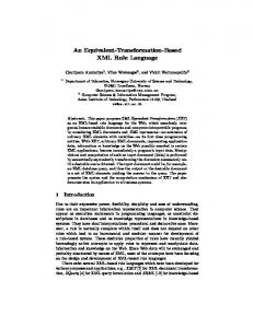
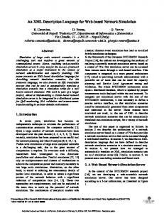
Figure 6. Jeoffrey’s user interface. Figure 6 shows a Jeoffrey user interface screenshot. The most left window is the root list box. The background window corresponds to the map that appears when a room is selected. Finally, the other three windows correspond to invoked entity control panels. Jeoffrey gathers the information stored in the blackboard to dynamically render the user interface. The blackboard graph includes an entity node for each room and for each entity. A relationship between a room and an entity reflects that the entity is located in that room. This way, Jeoffrey can easily ask for all the rooms and, for each of them, which entities are inside. Each entity includes several Jeoffrey’s parameters that help to render its graphical interface. Figure 7 illustrates the Jeoffrey interface information of a fluorescent XML instance. Bold font is used to highlight the Jeoffrey’s parameters. There are two paramSets. The first one is associated to the entity and contains three parameters. The image parameter defines its corresponding image file. The x and y parameters are the coordinates where this image will be drawn. The second paramSet is associated to the status property and defines its related widget. As we have mentioned above, the interaction with the entities is managed by a custom control panel composed of widgets. This panel is customized depending on the entity properties. Each property is rendered into a widget that allows interacting with the entity property. There are five different generic widgets: text areas, switches, sliders, list boxes and alarms. Text areas permit to change the value of a string. Switches act as a toggle button associated to onoff properties. Sliders correspond to properties that take a value from an interval. List boxes define a list of possible values where the user can choose one. And finally, alarms are colored labels that change their color depending on the value of the property.
Figure 7. XML entity representation As figure 7 shows, the fluorescent called Lamp_1 has only a status property. This property is associated with a switch widget. Besides, several switch parameters defining presentation features are established. These features are: •
The button text: this text changes depending on the state of the property. The “text_off” parameter is displayed when the light is off whereas the “text_on” parameter is showed when the light is on.
•
The button color: by default the color is gray when the light is off. When the light is on, the color is defined by the “color_on” parameter.
Figure 8 illustrates the rendered control panel for a florescent and the image painted on the map. Finally, the “cmd_off” and “cmd_on” parameters define the value of the status property that will be set when the button is pressed.
Figure 8. User interface for a fluorescent When a user clicks on the picture of an entity, Jeoffrey reads the descriptions of its properties from the blackboard, translates the properties to widgets and generates a custom control panel. If the entity has more than one property, the
Figure 9. Overview of the system control panel will be composed by the aggregation of the widgets corresponding to each property. Jeoffrey employs the blackboard as a proxy to interact with the physical entities, for instance, to change the speaker volume, switch on the lights, etc., and to receive the changes occurred in the environment. Jeoffrey is subscribed to every event. All the changes in the state of an entity are reflected in the user interface. For instance, if a property has associated a widget alarm, when its value changes, the blackboard will notify this to Jeoffrey and it will modify the color of the alarm widget. IMPLEMENTED ENVIRONMENT
Currently we have implemented a real intelligent environment that allows to control and interact with a fluorescent light, two reading lights, two dimmable lights, the main gate lock mechanism and an FM tuner with thirteen different radio stations, among other functionalities (such as sending messages, showing personalized paintings, etc.). All these devices are part of the laboratory number 407, so they hang from the path /lab407/device/ These devices already come with their common XML entity definition, their action and state method and their associated grammar template. The device manufacturer is in charge of providing this information, so an environment designer only has to declare the instances of the elements and their distribution in the environment. The environment designer declares the entities according to the template showed in the figure 2. If it is not necessary to customize the linguistic or web-based information for the current environment s/he will not have to declare any specific information related to the interfaces. Then the system adds the interface class information to the entity declaration. All this information is compiled to create the system representation file. With this file the system builds the blackboard, containing information about the environment and the interfaces (see an overview of the system in the figure 9). For instance, in our developed environment the environment designer only has to declare the seven device members of the laboratory 407. Given that there are some devices of the same type, s/he will have to customize some
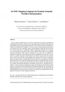
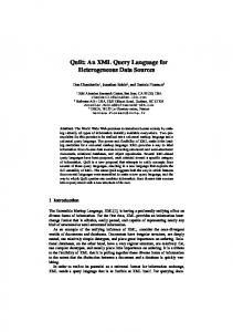
interface information. In this case s/he employs new linguistic information to distinguish between the two dimmable lights, adding to the location part the words left and right respectively (see another example in figure 4). A similar case occurs with the two reading lights. Finally, the entity declaration is customized by specifying the coordinates x and y for the Jeoffrey’s web-based interface. With this, the system automatically creates the blackboard. Whenever the web-based interface is executed it consults the blackboard to create the interface showed in the figure 6. The information for all the devices of the laboratory 407 is retrieved employing the following path /roomdevice/lab407/*/*/jeoffrey/*. The dialogue information is retrieved in a similar way and it forms a linguistic tree as the core of the spoken interface. Once the interfaces are created users can interact with the environment. The spoken dialogue interface allows natural interaction with the elements of the environment. Users can refer in different ways to the actions that can be taken with the devices and the system responds either uttering answers or executing actions. The interface supports interpretation of user sentences, based on the current physical context stored on the blackboard. A clarification request is produced when it does not have enough information to carry on an action. Besides, it supports anaphora resolution. The dialogue interaction adapts to the elements of the environment and their state. Answers and system actions vary depending on the elements declared for each environment. This is done by means of the linguistic tree obtained from the blackboard at startup. This tree contains all the possible interactions with the environment and the entities that support them. Again, this is an automatic process and the environment designer only needs to declare the entities that form the environment. A real example of an interaction produced in this environment is showed in the figure 10. It demonstrates how the system changes the interpretation of the same sentence for different states of the environment, interprets incomplete sentences or reacts when there are several entities of the same type.
User: Please, could you turn on the light?
ACKNOWLEDGMENTS
System: What light would you like to turn on?
This work has been sponsored by the Spanish Ministry of Science and Technology, project number TIC2000-0464.
U: The reading light, please.
REFERENCES
S: The one on the left or on the right.
1. Abrams, M., Phanouriou, C., Batongbacal, A.L., Williams, S., and Shuster, J.E. UIML: An ApplianceIndependent XML User Interface Language. In Proceedings of the Eighth International WWW Conference, Toronto, Canada, 1999.
U: The left light. (The system turns on the left reading light) U: Turn on the radio. S: What station do you prefer? U: I would like M80. (The system turns on the radio with M80) U: Please, turn it up. (The system turns up the radio volume)
2. Ali, M.A., Pérez-Quiñones, M.A., Abrams, M., and Shell, E. Building Multi-Platform User Interfaces with UIML. In Proceedings of CADUI, 2002. 3. Brumitt, B., and Cadiz, JJ. “Let there be light!” Comparing interfaces for homes of the future. In Proceedings of INTERACT '01, 375–382, 2001.
U: I would like you to switch off…
4. Coen, M.H. Design Principles for Intelligent Environments. In Proceedings of the AAAI Spring Symposium on Intelligent Environments, Palo Alto, California, 1998.
S: Do you prefer to switch off the left reading light or the radio.
5. Engelmore, R., and Morgan, T. Blackboard Systems. Addison-Wesley, 1988
U: The radio, please
6. McFarlane, N. Rapid Application Development with Mozilla. Bruce Perens' Open Source Series. Prentice Hall, 2003
U: More. (The system turns it up again)
(The system turns off the radio) U: I would like you to switch off… (The system directly turns off the left reading light)
7. Paternò, F., and Santoro, C. One Model, Many Interfaces. In Proceedings of CADUI, 2002.
Figure 10. Spoken interaction with the environment
8. Petzold, C. Create Real Apps Using New Code and Markup Model. MSDN Magazine, January 2004.
CONCLUSIONS
We have presented a graph model that allows to represent the entities of an intelligent environment and their relationships. This model is created using an XMLcompliant language, and it is stored in a global data structure, called blackboard. A blackboard middleware provides a set of operations to interact with the graph model. An application can add or remove entities, retrieve or modify their state, and subscribe to the changes done by other applications. Two user interfaces have been developed to interact with the environment. These interfaces are created by means of an extension of the environment XML model. The first extended language automatically creates a customized spoken dialogue interface. This language adds linguistic information to the XML model. The second one dynamically builds a web based interface. Again, new XML tags allow to specify GUI information. The middleware and the interfaces have been developed in a real environment. It is composed of several devices, including different types of lights, sensors, a door opening mechanism, an FM tuner, etc. Both interfaces provide real interaction with these devices.
9. Puerta, A. and Eisenstein, J. XIML: A Universal Language for User Interfaces. White paper. Available at http://www.ximl.org/Docs.asp. 2001. 10. Rayner, M., Lewin, I., Gorrell, G., and Boye, J. Plug and Play Speech Understanding. 2nd SIGdial Workshop on Discourse and Dialogue, September 2001. 11. Shafer, S., Brumitt, B., and Cadiz, JJ. Interaction Issues in Context-Aware Intelligent Environments. HumanComputer Interaction, 16, 363-378, 2001. 12. Trewin, S., Zimmermann, G., and Vanderheiden, G. Abstract user interface representations: How well do they support universal access?. In Proceedings of the 2nd ACM International Conference on Universal Usability, Vancouver, Canada, 2003. 13. Weiser, M. The computer of the 21st century. Scientific American, 265, 3, 66-75, 1991. 14. Weiser, M. The world is not a desktop. ACM Interactions, 1, 1, 7-8, 1994. 15. Zimmermann, G., Vanderheiden, G., and Gilman, A. Universal Remote Console Prototyping of an Emerging XML Based Alternate User Interface Access Standard. In Proceedings of the Eleventh International WWW Conference, Hawaii, 2002.