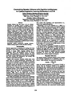
Extending Cognitive Architectures with Mental Imagery Scott D. Lathrop United States Military Academy D/EECS West Point, NY 10996
[email protected]
Abstract Inspired by mental imagery, we present results of extending a symbolic cognitive architecture (Soar) with general computational mechanisms to support reasoning with symbolic, quantitative spatial, and visual depictive representations. Our primary goal is to achieve new capabilities by combining and manipulating these representations using specialized processing units specific to a modality but independent of task knowledge. This paper describes the architecture supporting behavior in an environment where perceptual-based thought is inherent to problem solving. Our results show that imagery provides the agent with additional functional capabilities improving its ability to solve rich spatial and visual problems.
Introduction The generality and compositional power of sentential, symbolic processing has made it central to reasoning in general AI systems. However, these general symbolic systems have failed to address and account for inherently perceptual, modality-specific processing that some argue should participate directly in thinking rather than serve exclusively as a source of information (Barsalou 1999; Chandrasekaran 2006). Mental imagery is an example of such thought processing. In this paper, we argue that general, intelligent systems require mechanisms to compose and manipulate amodal, symbolic and modality-specific representations. We defend our argument by presenting a synthesis of cognition and mental imagery constrained by a cognitive architecture, Soar (Laird 2008). Empirical results strengthen our claim by demonstrating how specialized, architectural components processing these representations can provide an agent with additional reasoning capability in spatial and visual tasks.
Related Work One of the key findings in mental imagery experiments is that humans imagine objects using multiple representations and mechanisms associated with perception (Kosslyn, et al., 2006). For spatial and visual imagery, we assume there are at least three distinct representations: (1) amodal symbolic, (2) quantitative spatial, and (3) visual depictive. General reasoning with each of these representations is a key
John E. Laird University of Michigan 2260 Hayward Ann Arbor, MI 48109-2121
[email protected]
distinction between this work and others. The history of using these representations in AI systems begins perhaps with Gelernter’s (1959) geometry theorem prover and Funt’s (1976) WHISPER system that reasoned with quantitative and depictive representations respectively. Some researchers, to include Glasgow and Papadias (1992) and Barkowsky (2002), incorporated mental imagery constraints in the design of their specific applications. The CaMeRa model of Tabachneck-Schijf’s et al. (1997) is perhaps the closest system related to this work. CaMeRa uses symbolic, quantitative, and depictive representations and includes visual short-term and long-term memories. Whereas their shape representation is limited to algebraic shapes (i.e. points and lines), we leave the type of object open-ended. CaMeRa’s spatial memory is limited to an object’s location while ignoring orientation, size, and hierarchical composition (e.g. a car is composed of a frame, four wheels, etc.). Our system uses these spatial properties, providing significantly more reasoning capability. Cognitive architectures have traditionally ignored modality specific representations. ACT-R’s (Anderson, 2007) perceptual and motor systems focus on timing predictions and resource constraints rather than their reuse for reasoning. Some researchers have extended the perception and motor capabilities of cognitive architectures (e.g. see Best et al., 2002; Wray et al., 2005). Each contribution effectively pushes the system closer to the environment but requires ad-hoc, bolted-on components tailored for specific domains. These approaches assume that cognition abandons perceptual mechanisms after input rather than using these mechanisms for problem solving. Kurup and Chandrasekaran (2007) argue for general, multi-modal architectures and augment Soar with diagrammatic reasoning. They are non-committal as to whether diagrams are quantitative or depictive. Their current implementation uses strictly quantitative structures. Key differences include their proposal for a single, working memory containing both symbolic and diagrammatic representations. We propose separate symbolic and representation-specific short-term memories where perceptual representations are not directly accessible to the symbolic system. Whereas their diagrammatic system constrains the specific types of objects to a point, curve, or
region, we leave the type of object open-ended to any shape the agent experiences in the world or imagines by composing known objects. Wintermute and Laird (2008) extend Soar with a spatial reasoning system that focuses on translating qualitative predicates into quantitative representations and simulating continuous motion—extending the framework described here as it relates to spatial imagery. Gunzelmann and Lyon (2007) propose extending ACT-R with specialized, spatial processing that includes quantitative information. They do not plan to incorporate depictive representations without compelling evidence for their use. We hope to provide some evidence and argue that all three representations are necessary to achieve general functionality.
Experimental Environment In previous work, Lathrop and Laird (2007) demonstrated how extending Soar with quantitative spatial and visual depictive representations provided an agent with capabilities for recognizing implicit spatial and visual properties. However, the results were limited to solving internally represented problems. This paper extends those results to a dynamic environment where the agent must interpret and act on information from multiple internal and external sources. The U.S. Army’s work in developing robotic scouts for reconnaissance missions (Jaczkowski, 2002) motivates the evaluation environment. In support of this effort, we built a simulation modeling a section of two robotic scout vehicles that must cooperate to maintain visual observation with an approaching enemy (Figure1a). One scout, the section lead, is a Soar agent, modeled with and without mental imagery for evaluation purposes. The other, teammate, scout is scripted. The section’s primary goal is to keep their commander informed of the enemy’s movement by periodically sending observation reports (through the lead) of the enemy’s location and orientation. The agent cannot observe its teammate because of terrain occlusions. However, the teammate periodically sends messages regarding its position. The teammate continuously scans the area to its front (Figure 1b) and sends reports to the agent when it observes the enemy. The teammate can reorient its view in response to orders from the agent. The agent can look at the environment (Figure 1c) or its map (Figure 1d). To motivate the reasoning capabilities when using multiple representations, consider how the agent makes decisions in this domain. Typically, a scout follows these steps after initial visual contact: (1) Deploy and report, (2) analyze the situation, and (3) choose and execute a course of action (U.S. Army 2002). Analysis involves reasoning about friendly and enemy locations and orientations, terrain, and obstacles. If the scout leader does not know the locations of all expected enemy, then he might hypothesize where other enemy entities are (Figure 1d). Note that the hypothesized enemy in Figure 1d is not the same as the actual situation in Figure 1a but rather an estimate based on the agent’s knowledge of how the enemy typically fights.
Analysis involves visualizing the situation and mentally simulating alternatives. Using spatial imagery, an agent can imagine each observed entity’s map icon on its external map. If the agent is confident in the information, it can “write” it on the external map, in effect making it persist. As information changes the agent updates the map, keeping its perceived image of the situation up to date. Using the external map as perceptual background, the agent can then imagine key terrain (enemy goals), possible enemy paths, its viewpoint, and its teammate’s viewpoint. Using visual imagery to take advantage of explicit space representation in a depiction, the agent can imagine what portion of those viewpoints cover the possible enemy paths and then imagine alternative courses of action by simulating different viewpoints. Based on the analysis the agent decides if it should reorient itself, its teammate, or both. In summary, decision-making proceeds by combining perceptual representations with task specific knowledge to construct an imagined scene. Analysis emerges through the manipulation of symbolic, quantitative, and depictive representations. Retrieval of the resulting representations provides new information to the agent that it uses to reason and produce action in the environment.
(a) Actual situation
(b) Teammate’s view
(c) Agent’s view
(d) Agent’s perceived map/imagined situation Figure 1: Experimental Environment
Architecture Soar and its Spatial-Visual Imagery (Soar+SVI) module are the two major components in our system (Figure 2). Soar encompasses the symbolic representation. SVI includes the quantitative and depictive representations. It encapsulates high-level visual perception and mental imagery processing. Soar’s symbolic memories include a declarative, shortterm memory (STM) and a procedural, long-term memory (LTM). The symbolic STM is a graph structure (Figure 2)
representing the agent’s current state. Some symbols may represent an object (filled gray circle in Figure 2). These “visual-object” symbols emerge from the current perception or activation of a previously stored memory. They may be associated with non-visual symbols that augment the object with additional information (e.g., the object is an enemy scout). The visual-object symbol may have properties defining its explicit visual features and qualitative spatial relationships with other objects. Procedural LTM is a set of productions, some of which propose operators that a decision procedure selects for application. The application of an operator makes persistent changes to short-term memory and may send commands to a motor system, or, in SVI’s case, imagery processes. Processing occurs by iteratively proposing, selecting, and applying operators.
shape (i.e. a three-dimensional mesh of vertices and indices) and texture to support rendering a bitmap. The structure is a graph because multiple leaf nodes may share shape and texture (e.g. a shared wheel). A viewpoint facilitates the generation of a depiction from a particular perspective. Sentential, geometric algorithms are the basis for the computational processing that infers knowledge from this representation. The structure is sufficient for spatial reasoning between convex objects and simulating dynamical systems (Wintermute 2008). However, if reasoning requires specific shape or visual properties, a depictive representation is more appropriate. Current-Scene Object Viewpoint Visual-Object-1
… Visual-Object-2 A
Visual-Object-2
…
Visual-Object-2 B
Visual-Object-N
… Visual-Object-2 C
Shape, Texture
Figure 3: Object Map’s scene-graph and viewpoint data structures
Figure 2: Architectural overview with visual perceptual processing
Within SVI, the Visual Buffer (bottom of Figure 2) is a depictive memory activated from bottom-up visualperception or top-down imagery processing. In contrast to sentential symbols, space is inherent in the representation and the encoding is strictly visual information. The depiction as a whole represents shape, size, orientation, location, and texture from a specific perspective. Computationally, it is a set of 2D bitmaps with at least one bitmap representing either the egocentrically perceived scene or an imagined scene from a specific viewpoint. The system creates additional bitmaps to support the processing. The Object Map (right side of Figure 2) maintains the quantitative spatial representation of objects in the currently perceived or imagined scene by fixing an object’s location, orientation, and size in space. The Object Map uses a scenegraph data structure (Figure 3). The root node represents the perceived or imagined scene and children nodes are salient, visual objects. Figure 3 shows the number of visual objects to be N where N is hypothesized to be four to five based on working-memory capacity (Jonides et al., 2008). Intermediate nodes represent an object’s composition and contain translation, scaling, and rotation metrics to capture spatial relationships between objects. Leaf nodes represent
The remaining two memories in SVI are not associated with a particular representation but support reasoning indirectly. The Visual-Spatial STM (middle of Figure 2) is a shared memory between Soar and SVI. It is hierarchical with the root representing sets of extracted salient objects, spatial relationships, and visual features applying to the current scene. Each salient object may have subsequent levels in the hierarchy with its own feature, object, and spatial sets. Perceptual long-term memory (PLTM) is a container of prototypical objects where each object is a scene graph. A scene-graph in PLTM is distinct from the Object Map as the graph is not an instance in the current scene but rather a memory of an object’s shape, texture, and spatial configuration without a fixed frame of reference.
Visual Perception Our modeling of visual perception, to include the separation between “what” and “where” pathways is theoretical. We include it since psychological evidence indicates that mental imagery and vision share similar mechanisms thereby constraining the architectural design. Our ultimate goal is to incorporate realistic perception in the architecture. A Refresher process activates the Visual Buffer from sensory stimulus (bottom right of Figure 2). Upon activation, a “Saliency” Inspector marks relevant objects in the current scene and creates a symbolic structure for each salient object in VS-STM. Two parallel processes then initiate a more detailed inspection of the Visual Buffer, focusing on the marked objects. The “What” inspectors
extract features in support of recognition by matching features with shape and color in PLTM. Simultaneously, the “Where” inspectors extract the location, orientation, and size of the objects from the Visual Buffer and build the quantitative spatial representation in the Object Map. Both inspectors update the structures in VS-STM and symbolic results are sent to Soar where operators associate the input with existing knowledge (e.g. the object is an enemy).
Spatial Imagery An agent uses spatial imagery by invoking an imagery operator (top right of Figure 2). To construct a spatial image, the agent can compose two visual-objects from PLTM or add a visual-object from PLTM to the scene. Specialized processing units within SVI respond to the specific imagery command (Figure 4). The Constructor receives the operator’s symbolic information and builds the quantitative representation in the Object Map by combining each object’s general shape from PLTM with qualitative spatial knowledge from Soar. In the scout domain, the agent continuously analyzes the situation by imagining the friendly, enemy, and obstacle locations and orientations.
Visual Imagery If a depictive representation is required (e.g. to determine if the scout section has adequate visual coverage), the generate operator (Figure 4) initiates processing. The Refresher interprets the command and combines each object’s specific shape and texture from PLTM with the Object Map’s quantitative information to generate the bitmap in the Visual Buffer. Generation may render some or all of the visual objects in the Object Map and create one or more bitmaps to support visual reasoning. The VBManipulator transforms the images in the VisualBuffer using either standard image processing (e.g. edge detectors) or algorithms that take advantage of the topological structure and color using pixel-level rewrites (Furnas et al., 2000). Unlike sentential processing (e.g. Gaussian filters), pixel-level rewrites take advantage of the explicit topological structure and color of a bitmap. Similar to a production system, there are a set of rules with a lefthand side (LHS) and a right-hand side (RHS). Rather than predicate symbols, however, the LHS conditions and RHS actions are depictive representations that operate on the shared image. The color and shape of each LHS depiction, determines a match rather than the sentential structure. Figure 5 illustrates an example of two depictive rules. The top rule is a 1x2 rule stating, “If there is a black pixel adjacent to a gray pixel then change the gray pixel to a white pixel.” Similarly, the bottom rule is a 2x2 rule that states, “If there is a black pixel diagonally adjacent to a gray pixel then change the gray pixel to a white pixel.” The asterisks represent wildcard values and a rule may specify alternative rotations (90, 180, 270 degrees) for matching. Each rule can have arbitrary shape and color and a set of these rules can represent a high-level task in Soar (e.g. findenemy-path). Priorities enforce sequencing, and the processing iterates over the image while there are matches.
Figure 4: Mental imagery processes
The transform operator manipulates the Object Map’s quantitative representation through its Manipulator (Figure 4). The manipulation may change the viewpoint or transform (i.e. translation, rotation, scaling) a specific object. In the scout domain, the agent dynamically updates specific objects when observing (either visually or via a teammate’s report) changes to spatial relationships. The agent may also imagine different situations, effectively simulating hypothesized scenarios, and infer the changed spatial relationships. For example, the agent modifies the orientation of imagined views to determine if its team can improve coverage of enemy routes. When the agent or its teammate loses visual contact with the enemy, the agent can simulate movement with knowledge of a vehicle’s velocity. From SVI’s perspective, the objects it is manipulating are general—task knowledge remains encoded in Soar.
Figure 5: Example pixel rewrite rules
A way for the agent to analyze its team’s position is to imagine a hypothesized path from each enemy’s location to key terrain (Figure 6). The analysis should take into account the agent’s knowledge about the surrounding terrain and known obstacles. An algorithmic solution translated into a set of pixel rewrites is the following: (1) Mark all known obstacles and impassable terrain (known threshold values) with a color (yellow). Mark all other pixels gray. (2) Grow an iso-distance contour field of four colors avoiding any previously marked, barriers (Figure 6a). (3) Walk the contour field from source to sink, marking the path along the way (Figure 6b).
After the imagined path(s) are marked, the agent can generate each scout’s view to determine if there is adequate coverage (Figure 7).
processing in Soar. As a baseline, a third agent (Observer) and its teammate simply observe to their front and send reports without any attempt at re-positioning.
(a) Distance field flood (b) Path finding Figure 6: Demonstration of pixel-level rewrites
Figure 8: Measure of information over time
Figure 7: Agent imagining coverage of an imagined enemy path
After constructing and manipulating the representations, the agent can infer spatial and visual properties. The inspect operator (Figure 4) provides the symbolic query. For example, “what is the direction and distance between enemy scout-1 and the key terrain in the east” or “how much of the teammate’s view covers enemy-1’s hypothesized path (Figure 7)?” The appropriate “What” or “Where” process interprets the query and returns the symbolic results to Soar as described for visual perception. The reasoning uses abstract mechanisms rather than problem specific annotations. For example, “how much of the teammate’s view covers enemy-1’s hypothesized path?” proceeds as follows: (1) What is the topology between object-1 (the teammate’s view) and object-2 (the hypothesized path)? The inspector provides a symbolic “overlaps” result and stores a shape feature (shape-1) representing the overlap in VS-STM (Figure 4). (2) What is the scalar size (i.e. length) of shape-1? SVI calculates and returns the size of shape-1.
Figure 9: Number of reported observations
There are two evaluation metrics. The first is the amount of information the commander receives on the enemy’s location over time (Figure 8). The second metric is the number of reported enemy observations (Figure 9). Each reflects an average of 30 trials. In Figure 8, the x-axis is the current time and the y-axis measures the amount of information per unit time with 1.0 signaling perfect information and –1.0 indicating no information. The measure of information is an average of all three enemy entities at simulation time, t, calculated as follows: where:
Functional Evaluation Extending a symbolic architecture with mental imagery mechanisms provides an agent with functional capability that the system cannot achieve without it. To evaluate this claim, we created three agents modeling the lead scout. The first agent (Soar+SVI) observes, analyzes, and decides on a course of action by using symbolic, quantitative spatial, and visual depictive representations. The second agent (SoarSVI) uses the same task knowledge as the first agent but reasons using strictly symbolic representations and
(obsx,obsy) is the reported location of an entity at time, t and (actx,acty) is the actual location of an entity at time, t
The agent receives a positive score for a given enemy if at simulation time, t, a reported enemy’s location is within a 500 x 500 meter square area of the enemy’s actual location at that time. Otherwise, the information score is negative for
with a minimum score of -1.0. The “Tracker” in Figure 8 illustrates the amount of information a scout team provides if each scout observes one enemy at the beginning of the simulation and then “tracks” that entity to the simulation’s conclusion. Assuming no terrain occlusions, instantaneous message passing, and the third enemy not in vicinity of the tracked entities, the “Tracker” would receive an information score of (1.0 + 1.0 - 1.0) / 3 = 0.33 for each time unit. The results demonstrate that the Soar+SVI agent provides more information upon initial contact (the slope of its line in Figure 8 is steeper) and for a longer, sustained period. The reason is that the Soar+SVI agent is able to reposition its team more effectively as its analysis is more accurate. The Soar-SVI agent often under or overestimates adjustments resulting in the team missing critical observations. On average, the Soar+SVI agent sends more observation reports to the commander (Figure 9) indicating that the team has detected the enemy more frequently. The number of observation reports also shows that the agent is able to perform other cognitive functions (observe, send and receive reports) indicating that imagery is working in conjunction with the entire cognitive system.
Conclusion In this paper, we demonstrate that augmenting a cognitive architecture with mental imagery mechanisms provides an agent with additional, task-independent capability. By combining symbolic, quantitative, and depictive representations, an agent improves its ability to reason in spatially and visually demanding environments. Our future work includes expanding individual architectural components—specifically by pushing the architecture closer to sensory input. To investigate this in more depth, we are exploring robotics to determine how cognitive architectures augmented with mental imagery can provide a robot with higher-level reasoning capabilities. Paramount in this exploration is an understanding of how our perceptual theory incorporates typical robotic sensors (e.g. laser, stereoscopic video, global positioning system, etc.) and how imagery may prime robotic effectors (motor imagery).
References Anderson, J. R. (2007). How Can the Human Mind Occur in the Physical Universe? New York, NY: Oxford University Press. Barkowsky, T. (2002). Mental representation and processing of geographic knowledge - A computational approach. Berlin: Springer-Verlag. Barsalou, L. W. (1999). Perceptual symbol systems. Behavioral and Brain Sciences, 22, 577-660. Best, B.J., Lebiere, C., and Scarpinatto, C.K. (2002). A Model of Synthetic Opponents in MOUT Training Simulations using the ACT-R cognitive architecture. In Proceedings of the Eleventh Conference on Computer Generated Forces and Behavior Representation). Orlando, FL.
Chandrasekaran, B. (2006). Multimodal Cognitive Architecture: Making Perception More Central to Intelligent Behavior. AAAI National Conference on Artificial Intelligence, Boston, MA. Funt, B.V. (1976). “WHISPER: A computer implementation using analogues in reasoning,” PhD Thesis, The University of British Columbia, Vancouver, BC Canada. Furnas, G., Qu,Y., Shrivastava, S., and Peters, G. (2000). The Use of Intermediate Graphical Constructions in Problem Solving with Dynamic, Pixel-Level Diagrams. In Proceedings of the First International Conference on the Theory and Application of Diagrams: Diagrams 2000, Edinburgh, Scotland, U.K. Glasgow, J., and Papadias, D. (1992). Computational imagery. Cognitive Science, 16, 355-394. Gelernter, H. (1959). Realization of a geometry theoremproving machine. Paper presented at the International Conference on Information Processing, Unesco, Paris. Gunzelmann, G., and Lyon, D. R. (2007). Mechanisms of human spatial competence. In T. Barkowsky, M. Knauff, G. Ligozat, & D. Montello (Eds.), Spatial Cognition V: Reasoning, Action, Interaction. Lecture Notes in Artificial Intelligence #4387 (pp. 288-307). Berlin, Germany: Springer-Verlag. Jaczkowski, J. J. (2002). Robotic technology integration for army ground vehicles. Aerospace and Electronic Systems Magazine, 17, 20-25. Jonides, J., Lewis, R.L., Nee, D.E., Lustig, C.A., Berman, M.G., and Moore, K.S. (2008). The Mind and Brain of Short-Term Memory. Annual Review of Psychology, 59, 193-224. Kosslyn, S. M., Thompson, W. L., and Ganis, G. (2006). The Case for Mental Imagery. New York, New York: Oxford University Press. Kurup, U., and Chandrasekaran, B. (2007). Modeling Memories of Large-scale Space Using a Bimodal Cognitive Architecture. In Proceedings of the Eighth International Conference on Cognitive Modeling, Ann Arbor, MI. Laird, J.E. (2008). Extending the Soar Cognitive Architecture, Artificial General Intelligence Conference, 2008. Lathrop, S. D., and Laird, J. E. (2007). Towards Incorporating Visual Imagery into a Cognitive Architecture. In Proceedings of the Eighth International Conference on Cognitive Modeling, Ann Arbor, MI. Tabachneck-Schijf, H.J.M., Leonardo, A.M., and Simon, H.A. (1997). CaMeRa: A Computational Model of Multiple Representations. Cognitive Science, 21(3), 305-350. U.S. Army. (2002). Field Manual 3-20.98, Reconnaissance Platoon. Department of the Army, Washington D.C. Wintermute, S. and Laird, J. E. (2008). Bimodal Spatial Reasoning with Continuous Motion. Proceedings of the Twenty-Third AAAI Conference on Artificial Intelligence (AAAI-08), Chicago, Illinois Wray, R. E., Laird, J.E., Nuxoll, A., Stokes, D., and Kerfoot, A. (2005). Synthetic Adversaries for Urban Combat Training. AI Magazine, 26(3), 82-92.