Extending Reusable Asset Specification to Improve Software Reuse Soojin Park
Sooyong Park
Software Engineering Lab., Dept. of Software Engineering Lab., Dept. of Computer Science Computer Science Sogang University,1 Shinsoo-Dong, Sogang University,1 Shinsoo-Dong, Mapo-Ku, Seoul 121-742, Korea Mapo-Ku, Seoul 121-742, Korea +82 2 701 4797 +82 2 701 4797
[email protected]
[email protected]
Vijayan Sugumaran Decision and Information Sciences School of Business Administration Oakland University Rochester, MI 48309, USA +82 2 701 4797
[email protected]
(CBSD). CBSD is based on the assumption that there is sufficient commonality in many large software systems, and shifts the emphasis from programming software to composing software systems. However, current approaches to CBSD seem to be inadequate for the creation of reusable and changeable software architecture [2] from the following points of view.
ABSTRACT Even though many approaches for reuse have been introduced, software engineers are still hesitating to reuse existing software components. Two problems are the root cause of this situation. One is the difficulty in knowing whether the required software components are available. The other is the lack of information as to how to reuse the acquired components. To solve this problem, we introduce an extension to Reusable Asset Specification (RAS) and a process for supporting efficient reuse. We explain the process with a case study and evaluate through feedback from software engineers participating the case study.
First, CBSD does not provide adequate mechanisms to document design assumptions within the component itself. Because of this, various architectural mismatches occur [2]. Second, the information necessary for utilizing a component is misplaced or documented separately from the source code or executable code. As a result, even an acquired executable component is not reused due to lack of information about how to use it. Thus, software developers prefer time-consuming re-construction of software components in spite of the existence of reusable components at their disposal. So far, much of CBSD research has focused on developing well-defined components rather than creating ways of reusing developed components effectively. Our research mainly focuses on the latter issue. The objectives of this research, therefore, are:
Categories and Subject Descriptors D.2.13 [Software Engineering]: Reusable Software – reusable libraries, reuse models.
General Terms Management, Documentation, Design.
Keywords
• Developing a standard component structure and specification including artifacts from all the related development phases. We call such a component as “Multi-Phased Component” (MPC). • Providing a software development process for effective reuse using MPC. Our process relies on architecture driven component integration.
Software reuse, Reusable Asset, Component Based Development.
1. INTRODUCTION One of the crucial questions in software engineering is how to develop a high quality software system within the given schedule. As many business models are dependent on quick delivery of software systems, ‘time-to-market’ has become the most important requirement. It warrants reduction in development cycle time through improvement in productivity using an effective reuse mechanism [1], as well as sustaining good quality for the software product. Software reuse is generally conceived as a way for reducing the software development cost. Although various methods have been introduced during the last decade, the predominant method is component based software development
2. MPC (MULTI PHASED COMPONENT): A NEW EXTENSION OF RAS “Multi Phased Component” (MPC), is an extension of the default component profile of Reusable Asset Specification (RAS) ver.2.2 [3]. RAS is a standard for packaging reusable software assets from the Object Management Group (OMG). It provides four major sections – Classification, Solution, Usage and Related Assets – to represent the fundamental elements of an asset. Existing classes in RAS provide a way to document only the meta-level information. In the core RAS, high-level artifacts from different activities are documented as an instance of the ‘Artifact’ class. From this point of view, OMG provides a profiling technique for the extension of core RAS. In fact, categories of artifacts such as Requirement.Artifact, Design.Artifact, Implementation.Artifact, and Test.Artifact are identified in the default component profile of RAS.
Permission to make digital or hard copies of all or part of this work for personal or classroom use is granted without fee provided that copies are not made or distributed for profit or commercial advantage and that copies bear this notice and the full citation on the first page. To copy otherwise, or republish, to post on servers or to redistribute to lists, requires prior specific permission and/or a fee. SAC’07, March 11-15, 2007, Seoul, Korea. Copyright 2007 ACM 1-59593-480-4/07/0003…$5.00.
1473
Asset (from RAS)
Solution (from RAS)
Requirement (from Component Profile) name : string type : string reference : string id : string version : string digest-name : string digest-value : string access-rights : string
Architecture
Analysis
Design
Implementation
(from ACC Unique)
(from ACC Unique)
(from Component Profile)
(from Component Profile)
Test (from Component Profile)
Context (from Default Profile) name : String 0..1
Artifact (from Default Profile) name : string type : string reference: string id : string version : string digest-name : string digest-value : string access-rights : string
Diagram
FunctionalRequirement
NonfunctionalRequirement
(from ACC Unique)
(from ACC Unique)
Interface-spec (from Default Profile) name : string description : string
(from Component Profile) name : string type : string reference : string id : string version : string digest-name : string digest-value : string access-rights : string
Use-Case (from Component Profile)
0..*
0..*
0..*
Free-formSpecification
QualityAttribute
(from Default Profile)
(from ACC Unique)
value : string
attribute-name : string description: String
+diagram-dependency Operation (from Default Profile) name : string initiate-transaction : string description : string
Condition (from Default Profile) type : string description : string
0..* name : String conditionalParameters[] : String
Description (from Default Profile) value : String
1
VariabilityPointBiniding (from Default Profile) bindingTime : String bindingRule
0..* 0..*
conditionalParameter
VariabilityPoint
Model (from Component Profile) name : string type : string reference : string id : string +dependency 0..* version : string digest-name : string digest-value : string access-rights : string
Parameter (from Default Profile) name type : string description : string
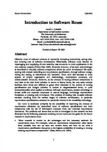
Figure 1. Major classes of the Solution section of MPC option and the binding time of an option [4]. In RAS, there is no room for specifying the options to create variants. To complement it, we have changed the type of ‘VariabilityPoint’ as a parameterized class. The dependency can represent which ‘Artifacts’ are variants of a given ‘VariabilityPoint’.
However, the classes in the default component profile of RAS 2.2 are inadequate for documenting components from various phases of software development. For example, assuming that one is searching for a reference architecture model, one has to examine all parts of the requirement and design artifacts that include fragments of architecture. Compared to RAS, MPC provides many more classes in the ‘Solution’ section. The newly added or revised classes in the ‘Solution’ section of MPC are highlighted in Figure 1.
Besides adding new classes to the Solution section, we have also defined additional context categories for efficient classification and retrieval of assets. The additional context categories are architectural style, design pattern, development method, application domain and programming language. Most of them will be used as keywords for the retrieval of MPC.
In extending the existing classes of RAS into MPC, the most important things considered are: z Architecture centric software specification
3. A SOFTWARE REUSE PROCESS USING MPC
The architecture can provide the rationale for a given design. In this context, Architecture, Nonfunctional Requirement, and QualityAttribute classes are added to the Solution section of MPC. By adding these classes, the architecture related parts can be exposed to MPC clients without any extra effort.
The proposed software reuse process is primarily geared towards the reuse of software components using RAS and not for a specific component development method per se. The proposed development process is also based on SOA [5] in that it adopts the three participants of SOA – service client, service registry, and service provider - as stakeholders. We also define a service as a workflow that reflects the user’s concern. Based on this definition, we map each flow of event in the use case specification into a service and package the artifacts that collaborate within the service as a MPC. Figure 2 shows the overall activities and the steps, which are composed from the perspective of the three stakeholders: a) MPC provider, b) MPC client, and c) MPC registry. The activities of each stakeholder are briefly described below.
z Separation of concern There is no element for specifying analysis related artifacts independently from design artifacts in existing profiles of RAS 2.2. Separating the analysis model can increase the amount of reuse because an analysis model itself can be reused even in different implement environments. To materialize the above benefit, we differentiate the ‘Analysis’ class from the ‘Design’ class in MPC. z Explicit documentation of variation point Information needed to be documented for variability could be categorized as the variation point, the elements affected by the
1474
M P C P ro vid er
M P C R eg istry Q uery S tatem ent
P 1. C reate each so ftw are asset
M P C C lient
discussed in a following case study. The MPC registry serves a list of candidate MPCs, which are ordered by similarity to the MPC client.
C 1. Q uery M P C w ith req uirem ents
R 1. S earch M P C List of searched M PC s
C reated so ftw are asset
R 2. M easure sim ilarity am o ng M P C s
4. CASE STUDY
C and id ate M P C s ordered by sim ilarity
To demonstrate the feasibility of the proposed software reuse process, we carried out a case study involving an ongoing software development project for a military logistics system. The development of this system was done by four different system integration companies, and each team worked in a different location. Furthermore, each division of the army, navy and air force had developed their own modules. As a result, redundant development efforts were spread across the military organization. The military logistics system is composed of four layers: presentation layer, business process layer, business logic layer and data layer. The fist two layers belong to application development area and the last two layers belong to domain engineering area. RUP was the development method used for each component and C++ was the implementation language. Below, each activity is described for the following context: An architect has assigned the development of a component for a new service to a developer. As for now, some development teams in charge of other categories of items have already constructed similar services. Among activities in Figure 2, the processing of P1 is the same as the processing of C3 and does not participate in the above given context. Thus we omitted the explanation of P1.
P 2. C o m p o se a M P C .ras
C 2. U nd erstand the retrieved M PC
M PC A rtif actA rtif act A rtif actA rtif act
P 3. Transfo rm M P C info . Into the o nto lo g y m o d el
.ras files
o nto lo gys
O nto lo g y
C 3. C reate ad ap ter class (G o to P 2)
feature grap hs
Figure 1. Activity overview of a software reuse process MPC Clients are in charge of constructing a system by reusing existing software components. They create a query statement for searching MPCs that are similar to the input conditions. Retrieval of MPCs is done by MPC registry. Assuming that the MPC client retrieved the most relevant MPC that meets the requirements, he/she determines how to utilize the acquired component in the target system by studying the information contained in the MPC structure. It is not necessary to go through the source code or heaps of files for grasping the acquired component. When the MPC client understands the acquired component and its relationships to other related components, he/she can set the strategy for reusing it. If there is a need to create new adapter classes to reuse the acquired components, the MPC client does it in accordance with the design strategy. The newly created classes and related artifacts go with the activity flow of MPC Provider.
The automated environment for supporting our software reuse process is currently under construction. Hence, the result artifacts referenced in this section are created manually.
4.1 Query MPC with Requirements (C1) According to the above context, the developer plays the role of a MPC client. One of the requirements for adding a new service is: “To estimate the needs of next year for various medical related things.” With this requirement, the component client creates query statements by matching keywords from requirements and items of MPC structure.
The MPC provider publishes reusable software assets. All newly constructed artifacts become input to the “Compose a MPC” activity. Each artifact is mapped into a class or attribute in MPC. All the artifacts in an MPC are archived in a .ras file and moved around together. OMG provides the mechanism for mapping a RAS to a .ras file and MPC also uses this mechanism. The MPC provider registers a .ras file into MPC storage. This transformation is used for the semantic retrieval of components based on relationship between classes in RAS. Among various knowledge representation techniques for ontology model, frame based representation [6] and feature graph [7] are used. Newly developed adapter classes in MPC are mapped into a frame [6], according to the transformation rules between UML notation and frame based representation. The MPC provider also updates the feature graph. The feature graph shows the terms (concepts) encapsulated in components and relationships between them from the perspective of a feature. These transformations of data after the development of a new component are preparations for other successive reuse work.
Table 1. A list of retrieved MPCs Retrieved MPC
Item Category
Criterion
Dev.Method
Prog. Language
BudgetMngnt
Food
# of person
RUP
C#
WartimeBudget
Ammunition
# of weapon
UML Components
C++
ComposeBudget
Commodity
# of crops
RUP
C++
EstimateBudget
Equipment
# of equipment
RUP
C#
4.2 Search MPC (R1) The retrieval of MPCs can be done according to the structure of MPC, which defines semantic information about a component and related software artifacts. Priorities exist in exploring each element of MPC to increase retrieval efficiency. The order of priority is (1)‘Classifiaction’ sections, (2) ‘Solution.Design. Interface-Spec’ class, (3)‘Solution.NonfunctionalRequirement. QualityAttribute’ class, and (4)other elements. This order is for narrowing the scope of retrieval. The results of the retrieval are shown in Table 1. The ‘criterion’ is a unit for calculating the quantity needed for an item in the military logistics domain. For example, the criterion of BudgetMngt MPC is ‘person’. It means that the calculation of the quantity needed for item in Budget MPC is based on the number of person(s). In the military logistics
The MPC registry finds the requested MPCs from MPC clients. Specially, searching is composed of two phases. The first phase is for searching candidate MPCs to be reused. If the candidate MPC list is available, the second phase is used for selecting the closest one compared to the required MPC from the ones found through the first phase. A similarity computation is done using the ontology model. In particular, the feature graphs are used for similarity computation. Details of similarity computation are
1475
domain, item category, criterion, development method, and programming language are the key features for systems development.
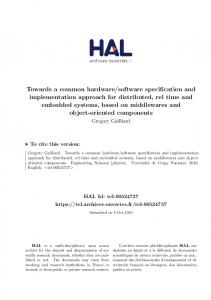
(Equipment, Equipment) + Dmethod(RUP, RUP) + Dpl(C#, C++) = 35 + 0+ 0 + 8 = 43 From the above results, ‘EstimateBudget’ component is the closest to the required component. However, the calculated results are not absolutely right because the weights on arcs are based on previous development experiences. Thus, the final result of this activity is ordered list of candidate components besides the closest one: EstimateBudgetÆComposeBudgetÆWartimeBudgetÆ BudgetMngnt.
4.3 Measure Similarity among MPCs (R2) The degree of similarity between the required MPC and actual MPCs is measured by closeness [7]. The closeness relation is added to capture the notion that new components can be constructed via the modification of existing constructs. The weight on an arc in the feature graph represents the effort needed for modification. Effort can be measured using various metrics. Based on previous modification experiences, we use average man-hour(s) with integer format as the weight. In Figure 3, the weight from ‘Commodity’ to ‘Food’ in the feature graph for ‘Item Category’ is 35. It means that the average time needed to construct the ‘Food’ component by modifying the ‘Commodity’ component is 35 man-hours. The arc from the node ‘ θ ’ to another node represents the man-hours needed for development from scratch and the weight on the arc going into the ‘θ’ node is always zero.
35
38
39
θ
E q uip m ent
45
0
0
θ
30
23
16 55
9
0
0
45
35 UM L C o m p o nents
M ed ical S tuff
F eature: Item C ateg o ry
F eature: D evelo p m ent M etho d
9 C ro p s
P erso n 49
0
11
41
19 37
32 0
12
Java 43
0
θ
22
C ++
15
F eature: C riterio n
• Ψ: a feature space
θ 26
E q uip m ent
0
0
0
W eapo n
f ∈ψ
• Dc : closeness comparator
RUP
53
C o m m o d ity
where,
• D f (t1 , t2 ) : minimal distance from
42 0
0 31 0
Closeness distance between a required component ‘B’ for the target system to an actual MPC ‘A’ found in the repository can be calculated from the feature graph using the following expression [7]: D c ( A , B ) = ∑ D f ( A. f , B . f )
A m m unitio n
Fo od
37 11 8
18
22
0 C#
F eature: P ro g ram m ing Lang uag e
Figure 2. Feature graphs for calculation of closeness between components
t1 to t 2
• D f : feature comparator
4.4 Understand the Retrieved MPC (C2)
According to the feature graphs in Figure 3, the closeness between the required component and the searched actual MPC is derived as follows: z Ψ = {item category, criterion for calculation of needs quantity, development method, programming language} z required component = {Medical Stuff, Equipment, RUP, C++} z BudgetMngnt = {Food, Crops, RUP, C#} z WartimeBudget = {Ammunition, Weapon, UML Components, C++} z ComposeBudget = {Commodity, Crops, RUP, C++} z EstimateBudget = {Equipment, Equipment, RUP, C#} z Dc(BudgetMngnt, required component) = Dcategory(Food, Medical Stuff)+Dcriterion(Crops, Equipment)+Dmethod(RUP, RUP)+Dpl(C#, C++) = 47 + 37 + 0 + 8 = 92 z Dc(WartimeBudget, required component) = Dcategory(Ammunition, Medical Stuff)+ Dcriterion (Weapon, Equipment) + Dmethod(UMLComponents, RUP)+ Dpl(C++, C++) = 55 + 12 + 30 + 0 = 97 z Dc(ComposeBudget, required component) = Dcategory(Commodity, Medical Stuff)+ Dcriterion (Crops, Equipment) + Dmethod(RUP, RUP) +Dpl(C++, C++) = 16 + 37+ 0 + 0 = 53 z Dc(EstimateBudget, required component) = Dcategory(Equipment, Medical Stuff)+ Dcriterion
1476
The main sources of information for understanding the context of a given MPC are the ‘Usage’ section, variability point related portion of the ‘Solution’ section, Interface-Spec related part of ‘Solution’ section and the ‘Classification’ section. In this case study, the most similar component to the required component is ‘EstimateBudget’. However, ‘EstimateBudget’ MPC does not provide all the expected functionality of the required component. So, we searched again and retrieved the MPC that has the functionalities which are unsatisfied by ‘EstimateBudget’ and found ‘ComposeBudget’ MPC.
4.5 Create Adapter Class (C3) If the interface of the adapted MPC does not fully satisfy the requirements by itself, one or more adapter classes are needed to provide interoperability between adapted MPCs and required MPC. One can use delegation or specialization in creating an adapter class. In the case study, the required component is named as ‘DrawBudget’. The ‘Estimate-Budget’ component is specialized and ‘ComposeBudget’ is delegated for the construction of it. Figure 4c shows the fragment of class diagram for the ‘DrawBudget’ MPC. An adapter class ‘PlanBudget_8’ specializes the ‘Estimate-Budget’ class and has a delegation to the ‘Component-Budget’ class. This step also involves modifying the internal classes according to the ‘VariabilityPoint’ specification in the retrieved MPC. The information for variability point, variants, conditional parameter and binding time should be already specified in the adapted MPC. For example, Figure 4a shows elements of the MPC structure for
Items
Context (from Default Profile)
name : String 0..1 conditionalParameter
VariabilityPoint name : String conditionalParameters[] : String
0..*
Artifact (from Default Profile)
name : string type : string reference : string id : string version : string digest-name : string digest-value : string access-rights : string
1
VariabilityPointBiniding (from Default Profile)
bindingTime : String bindingRule
Description (from Default Profile)
value : String
(a) Variab ilityP o int related elem ents o f M P C VariabilityPoint .name
PlanBudget_8
Type:
Instance
A-Kind-of:
EstimateBudget_5
Descendants:
Empty
Has-part:
BudgetAcc_8
Semantic_link_ from:
Empty
Semantic_link_to:
Empty
Slot #1 Slot name: Data type: Value: Condition: Argument: If-required: If-shared: If-unique:
mBudgetAcc_8 Instance Empty Any BudgetAcc_8 Checked Checked Checked
EstimateBudget_5
Slot #2 Slot name: Data type: Value: Condition: Argument: If-required: If-shared: If-unique:
X-1_BudgetAmnt Single Zero Any Empty Checked Checked No Checked
…
…
Slot #5 Slot name: Data type: Value: Condition: Argument: If-required: If-shared: If-unique:
IncDec_Ratl String Empty Any Empty Checked Checked No Checked
PlanBudget_8 X-1_BudgetAmnt : single = zero X_BdgtReqAmnt : single = zero IncDec : single = zero IncDec_Ratl : string = space
1
C lass to Fram e
VariabilityPointBinding
.value
1
BudgetAcct_8 DtlAcctNm : char = space DtlAcctCd : char = space MDtlAcctNm : char = space MDtlAcctCd : char = space PjtNm : char = space PjtCd : char = space DtlPjtNm : char = space DtlPjtCd : char = space
(c) A n ad ap ter class in ‘D raw B ud g et’ M P C
Description
.conditional parameters
Contents
Name:
.binding Time
.bindingRule
Artifact .name
Item Category
[0]medical equipment
Drawing of budget for medical stuff
Runtime binding
If itemcode is started with ‘8e’, predefined class(es) are set as active in the system.
AdapterCD_78
War_Peace
[0] peace time
Budget calculation for peace time
Runtime binding
If timing discriminator is set as ‘P’, default classes are collaborated in behavior of the component
BudgetAcct PlanBudget FundReq …(omitted)
[1] war time
Budget calculation for war time
Runtime binding
If timing discriminator is set as ‘W’, predefined classes for wartime is set as active in the system
WarItemCtlg WBudgetNeed WarBudgetCT-RL
(b ) Value o f each elem ent fo r sp ecifying variab ility o f ‘D raw B ud g et’ M P C Figure 3. VariabilityPoints and adapter class component is done by class-level adaptation. Hence, to easily capture these class-level semantics in MPC without visiting each class model, the information about adapter class(es) is transformed into ontology models. Among the knowledge representation methods of ontology, frame based representation (FBR) [6] is used in this approach because elements of FBR are very similar to object oriented concepts. There exists a connection between frame systems and object-oriented programming [8]. The transition rules from UML elements to frame elements are as follows:
specifying variability and Figure 4b shows an example of the mapping between constructed artifacts of ‘DrawBudget’ and the VariabilityPoint related part of ‘DrawBudget’ MPC.
4.6 Compose an MPC (P2) Composition of an MPC with developed software artifacts is done after unit testing. The coverage of an MPC is defined as related artifacts for satisfying a given service such as the flow of event in Use-Case specification, sections of software architecture, analysis/design models, implemented classes in the application area (the presentation layer and the business process layer in this case study), and test cases for the flow of event. All the artifacts in an MPC are zipped into an archive file. The extension name of this archive file is “.ras” and its format is defined by OMG. MPC follows the archiving mechanism of RAS for interchangeability. Generally, this archiving step is supported by automated tools. In our case study, this step is done using IBM Rational Software Architect 6.0. The ‘manifest.rmd’ file is an XML file that is the entry point for traversing the zipped artifacts in an MPC.
• Class nameÆFrame name • Class typeÆFrame type • relationshipÆA-Kind-Of, Descendants • relationshipÆ Has-part • relationshipÆSemantic-link-from/ Semantic-link-to • AttributeÆSlot As Figure 4c shows, the frame ‘PlanBudget_8’ is transformed from ‘PlanBudget_8’ class, and the newly defined relationship from the creation of adapter classes could be reflected in the ontology model.
4.7 Transform MPC Information into the Ontology Model (P3) The MPC structure is helpful for understanding component-level context. However, information about individual classes in the MPC is not disclosed in the MPC structure itself. Even though the unit of reuse is a component, essential work for reuse of existing
5. EVALUATION As a result of the case study, we gathered feedback from the participating engineers. As a metric to demonstrate the
1477
such as product line engineering, our approach for software reuse using MPC does not require much initial work for implementing the reuse model in different projects. It only requires the arrangement of artifacts spread across in repositories into the MPC structure. It is of interest to software engineers who are worried about heavy investment, which can cause the delay in their usual development work. Furthermore, MPC is not mutually exclusive with other approaches for software reuse such as CBSD or product line engineering. It can accelerate the benefits gained from them.
improvement in productivity from MPC based reuse process, we selected the elapsed time. Table2 shows the variation in the elapsed times for each arc of the feature graph. For example, the number on the arc from ‘Equipment’ to ‘Medical Staff’ signifies the average effort in the development of a component related to ‘Medical Stuff’ feature by reusing ‘Equipment’ related components. Without the use of MPC, the previous average effort was 35 man-hours. The effort depicted in the feature graphs of Figure 3 is the average effort computed from historical data, which was gathered through questionnaire and interviews of engineers who worked on the Military Logistics system. As a result of using MPC in the case study, the newly measured effort is 29 man-hours. Comparing with the old average effort, it has reduced by 7 man-hours. In this way, we compared the old average efforts and the newly measured efforts from the use of MPC. From the data shown in Table 2, it can be seen that 20% of the effort (man-hours) in adapting existing components is reduced as a result of using MPC. In case of programming language, it is totally dependent on the source code implementation style. Thus, there was no positive change in the development effort even with using MPC.
While the results from our initial work are encouraging, further work is needed to address various issues. For example, an automated framework for supporting the software reuse process such as a search engine that can be substituted for MPC registry should be created. Efficient mechanisms for adapting the components and creating adapter classes should be developed. Steps for adopting our software reuse process in an industrial setting should also be explored.
7. ACKNOWLEDGMENTS This research was supported by University IT Research Center Project (ITRC) in Korea.
The developers have already become familiar with their daily development activities from prior projects. Thus, just the proficiency from practicing in the same development environment can not explain the reduction in effort. The increased productivity is due to the fact that developers did not have to rummage through documents unrelated to the required component by using MPC based reuse process. Our approach would even work in an organization that has never tried software reuse before. In view of the results the case study, we are convinced that this approach can lead to efficient reuse in distributed development teams.
8. REFERENCES [1] Boehm B. W., Pendo, M. H., Pyster, A. B., Stuckle E. D. and William, R. D. A Software Development Environment for Improving Productivity, IEEE Computer, Vol. 17, Issue 6(June 1984), 30-44. [2] Keller, R. K. and Schauer, R. Design components: towards software composition at the design level, In Proceedings of International Conference on Software Engineering(ICSE 1998), (19-25, April 1998), 302–311.
Table 2. Variations in effort from using MPC N ew ly m easured effort (M P C -B ased R euse)
Variatio n
To
O ld average effort (C ode-B ased R euse)
A rc Feature From Item C atego ry
Foo d
M edical S tuff
47
27
-43%
Item C atego ry
A m m unitio n
M edical S tuff
55
38
-31%
Item C atego ry
C om m odity
M edical S tuff
16
15
-6%
Item C atego ry
E quipm ent
M edical S tuff
35
29
-17%
C riterion
C rop s
E quipm ent
37
25
-32%
C riterion
W eap on
E quipm ent
12
7
-42%
D evelop m ent M etho d
U M L C om po nents
RU P
30
28
-7%
P rogram m ing Language
C#
C ++ To tal
8
12
50%
240
191
-20%
[3] OMG, Reusable Asset Specification, Available Specification Version 2.2 formal/05-11-02. [4] Clements, P., Bachmann, F., Bass, L, Garlan, D., Ivers, J, Little, R., Nord, R. and Stafford ,J. Documenting Software Architectures, Addison-Wesley, Reading, MA, 2003. [5] Erl, T. Service-Oriented Architecture (SOA):Concept, Technology, and Design, Prentice Hall PTR, Reading, NJ, 2005. [6] Gomez-Perez, A., Fernandez-Lopez, M. and Corcho, O. Ontological Engineering : examples from the areas of Knowledge Management, e-Commerce and the Semantic Web, Springer-Verlag London Ltd. Reading, Oct. 2003.
6. CONCLUSION We have proposed an extension to RAS, named MPC, and a process for supporting efficient reuse. We also carried out a case study to demonstrate its feasibility and evaluated it by comparing it to an existing code-based software reuse process. We have shown encouraging results from using the new software reuse process. This process helps in the reduction of effort in reusing existing components by decreasing the time for searching and understanding them. Regarding the trade-off between the effort in packing of MPC and the effort saved from using the software reuse process, the gains are bigger. Compared to other approaches
[7] Ostertag, E., Hendler, J., Prieto-Daz, R. and Braun, C. Computing Similarity in a Reuse Library System: An AIBased Approach, ACM Transaction on Software Engineering and Methodology, Vol. 1, No. 3(July 1992), 205-228. [8] Lassila, O. and McGuinness, D. L. The role of Frame-Based Representation of the Semantic Web, Electronic Transactions on Artificial Intelligence (ETAI) Journal: area The Semantic Web, To appear, 2001.
1478