Specifications. Keywords. Non-functional Requirements, Requirement Verification, SysML,. Model-based System Design, Information System Architec- ture. 1.
Extending SysML to explore Non-Functional Requirements: The Case of Information System Design Anargyros Tsadimas, Mara Nikolaidou, Dimosthenis Anagnostopoulos Department of Informatics & Telematics, Harokopio University of Athens 70 El. Venizelou Str, 176 71 Athens, Greece {tsadimas, mara, dimosthe}@hua.gr ABSTRACT
11] and can be effectively accommodated by Systems Modeling Language (SysML) [5], defined as an extension of the UML metamodel [3]. Non-functional requirements (NFRs) [10] play a significant role during system design, since they depict the conditions under which specific system components should operate, leading to alternative design decisions [14]. Furthermore, proposed design decisions should be evaluated [7] and properly adjusted until all imposed requirements are verified. SysML provides a discrete diagram to define requirements and the relations between them in a qualitative fashion. Non-functional requirements are also described in a quantitative fashion using for example non-functional properties as defined in ([4]). Furthermore, their verification must be performed using quantitative methods, for example simulation. The description of non-functional requirements is a quantitative fashion was explored in UML profiles proposed for specific domains. In [6], performance characteristics are defined as discrete entities, associated to information system elements, and described using qualitative parameters. In Categories and Subject Descriptors MARTE, a UML profile supporting the specification of realtime and embedded systems [4], Non-Functional Properties H.1 [Information Systems Applications]: Models and (NFPs) are introduced to specify semantically well-formed Principles; D.2.1 [Software Engineering]: Requirements/ non-functional quantitative properties (e.g., throughputs, bandSpecifications widths, delays, memory usage), combined through Value Specification Language (VSL) to formulate algebraic and Keywords time expressions. MARTE profile, which is based in UML, Non-functional Requirements, Requirement Verification, SysML, does not support the notion of requirement introduced in Model-based System Design, Information System ArchitecSysML. Instead, non-functional annotations are associated ture to system design entities to indicate non-functional characteristics. Non-functional annotations defined using VSL enables their automated validation, verification and trace1. INTRODUCTION ability, using external tools. In [1] strategies to apply SysML System design is an important phase of system engineerand MARTE profile in a complementary manner to model ing, determining system architecture (i.e., the way system embedded systems were suggested in a high-level fashion, incomponents should be synthesized) to satisfy specific redicating the potential to combine non-functional properties quirements. It is commonly performed in a model-based and VSL expressions define in MARTE with SysML requirefashion, where activities constituting the design process are ments for the description of non-functional system characaccomplished by developing models of increasing detail [2, teristics. As far as NFRs are concerned, MARTE profile focuses on performance and scheduling properties of system components. Their verification can be explored using external tools. Permission to make digital or hard copies of all or part of this work for personal or classroom use is granted without fee provided that copies are To explore quantitative NFRS, a SysML extension to efnot made or distributed for profit or commercial advantage and that copies fectively depict and verify them is needed. In this paper, we bear this notice and the full citation on the first page. To copy otherwise, to propose the extension of basic SysML concepts to: republish, to post on servers or to redistribute to lists, requires prior specific a) describe, manage and verify non-functional requirepermission and/or a fee. ments, vital for system design and SAC’12 March 25-29, 2012, Riva del Garda, Italy. Model-driven system design is facilitated by SysML language, which provides distinct diagrams to describe system structure and components, explore allocation policies and identify system requirements. While non-functional requirements play a significant role in system design, their are not effectively supported by SysML. This paper emphasizes on a SysML extension to facilitate the effective description and verification of non-functional quantitative requirements. The introduction of a distinct SysML diagram to explore evaluation results enhances requirement verification capabilities, while the visualization of verification process helps system engineers to explore design decisions and properly adjust system design. Based on the proposed SysML extension, a profile for Enterprise Information System architecture design was developed. To demonstrate the potential of the proposed approach, the description and verification of software performance requirements using this profile are discussed, as an example.
Copyright 2011 ACM 978-1-4503-0857-1/12/03 ...$10.00.
b) include a discrete diagram serving system evaluation and requirement verification. The proposed extensions are applied in designing the architecture of enterprise information systems (EISs). For this purpose a SysML profile was implemented as a plugin to the MagicDraw modeling tool [9]. To explain the proposed concepts software performance requirements are discussed, as an example. The rest of the paper is organized as follows: In section 2, the extension of basic SysML concepts to explore NFR quantitative description and verification is discussed. In section 3, the EIS Architecture Design SysML profile based on the proposed extensions is briefly presented, emphasizing software performance requirements as an example. Conclusions and future work reside in section 4.
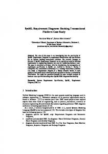
2. SYSML EXTENSION TO SUPPORT NFRS Requirements in SysML are described, as class stereotypes, in an abstract, qualitative manner, since they are specified by two properties, id and text, corresponding to a simple description. However, SysML specification suggests to use the stereotype mechanism to define additional properties for specific requirement types. Requirements can be grouped in packages based on common characteristics, as their category (for example functional or non-functional) or the activities they are related to (for example software or hardware requirements) forming a multi-level hierarchy. SysML includes specific relationships to relate requirements with other requirements (indicating the way they affect each other) or other model elements. The containment relationship, defined between requirements, indicates that the composite requirement is realized if and only if all the contained ones are realized. In this way, an abstract requirement may be composed of more specific ones, or a complex requirement may be described in a more detail fashion. In the case of system design, the notion of composite requirements is essential to indicate the way a requirement defined for the system as whole may be described in terms of the detailed requirements defined for system components. The deriveReqt relationship indicates that a specific requirement is derived by others. Since relationships do not have properties, the way requirements are specified is not depicted. Requirements should be satisfied by model elements belonging to other diagrams (SysML satisfy relationship). For this purpose, requirements may participate into other diagrams, enabling the exploration of the relationship between requirements and design decisions. SysML provides the means to describe a set of tests, which should be performed to verify whether a requirement is satisfied by system components. To depict such an activity, the test case entity, included in Requirement diagrams, is introduced. A test case is related o one or a set of requirements for their verification, while it is described through a behavior diagram (for example activity or state machine diagram) corresponding to the activity (as a set of tests) performed to verify related requirements. The way requirements are handled in SysML is summarized in figure 1. Since non-functional requirements (for example performance requirements) are described using both qualitative and quantitative properties, a quantitative method, such as simulation, should be employed to produce the necessary data for their verification. There are many tools and methods suggested to simulate SysML models and integrate
Figure 1: SysML Requirement representation SysML with different simulation languages either for continuous or discrete event simulation [12, 8, 13]. The concept of the test case is not supported by any of them. In such case, the way system evaluation is performed, conforms to the corresponding simulation method. Thus, the definition of test cases is of less importance, since they could only be used to specify the conditions under which the system should be evaluated and not the evaluation method itself. Furthermore, the results of the tests performed either by a test case or using simulation to verify requirement satisfaction are not included in SysML models. Such information is crucial for the system engineer to adjust system design or relax imposed requirements. When SysML is used for system design, as for example in EIS architecture model-based design, non-functional requirements are emphasized. To be accurately defined, nonfunctional requirements should be described using quantitative properties, in a similar fashion as the non-functional properties defined in MARTE UML profile [4]. Since, nonfunctional requirements may not always be described in an exact fashion, value deviation of quantitative properties should be allowed, to indicate for example that the response time for a specific service should be 4 to 5 seconds. In the same rational, maximum, minimum or average values should be described. Thus, more than one properties should be available for its description. Furthermore, derived quantitative properties of non-functional requirements should be automatically computed. The deriveRqt relationship indicates only the fact that the derived requirement is related to one or more others. It does not provide any information about the way the requirement may be derived, which may be depicted by indicating the way its quantitative properties are computed based on properties of the requirements it is derived from. Thus, a computation formula property should be defined for derived requirements. The computation formulas may involve heuristics and become complicated. SysML requirement entity must be extended to a) effectively represent the quantitative aspects of requirements and b) the way derived requirements should be computed. Constraints, specific purpose languages as VSL [1] or scripts can be applied to derived requirements to enforce the automatic computation of derived properties, while computation algorithms must also be integrated in the SysML model. It should be noted that the specification of computation formulas is meaningfull only if it is actually executed and quantitative properties are calculated. Non-functional requirements must be satisfied by system components included in any of the system design diagrams.
Figure 2: Extending SysML to explore NFRs In such case, in order to decide whether a non-functional requirement is verified, the designer may have to explore if the value of a quantitative property is satisfied by the related system components. To perform such a task, the comparison of specific evaluation results for each system component and related requirements properties should be performed, which leads to the need to integrate evaluation data into the system model. The SysML test case, as a concept, is focused on depicting how to evaluate model element satisfying a specific requirement, while integrating evaluation results into the system model is not considered. In the case of system design, non-functional requirements are verified in a quantitative fashion by evaluation scenarios instead of test cases. An evaluation scenario should facilitate both a) the definition of the conditions under which the system will be evaluated (probably using simulation) and b) the depiction of the evaluation results, so that the system engineer may be directly informed of requirement verification. An evaluation scenario comprises of evaluation entities, used to evaluate model elements, to verify the corresponding requirement or requirements and can be described with block definition diagrams. Since an evaluation scenario is introduced to specify the conditions under which the system design should be explored, it involves the evaluation of all model elements, thus it is used to verify a composite, abstract NFR (for example the system performance must be high), constituting of more specific ones (for example service time should be between 3 to 5 seconds). When an evaluation scenario verifies a composite requirement or a set of requirements, it should be used to verify all the included requirements. System design evaluation is usually performed via simulation. Regardless of the method used to perform system evaluation, evaluation elements have input properties, related to evaluated model elements, and output properties, depicting evaluation data. Based on the value of output properties, requirements are verified. In the case of nonfunctional requirements described in a quantitative fashion, an appropriate comparison method should be defined for the specific requirement, based on the output properties of all related evaluation entities. Such a method could be defined for example using a Parametric Diagram or executable scripts, associating requirement quantitative properties to
evaluation entity output properties. As already mentioned, to simulate a SysML model using a specific simulation method, simulation-specific characteristics should be included in the model. Such properties may be incorporated into evaluation entities, thus evaluation specific information does not have to be included in a system model designed by the system engineer, promoting discrete activity independence. During system design, NFRs may also used to depict specific behavior forced on system components (for example the way a traffic generator may behave under heavy traffic conditions). In such a case, there is no point in verifying the requirements. The corresponding evaluation entity may conform to them, since they specify conditions under which the system design should be evaluated. The same requirement or requirements may be verified more than once, by evolving evaluation scenarios, as the system design is re-adjusted. Evaluation data and conditions included in them should be integrated in the SysML model. Thus, evaluation scenarios should be grouped into a distinct diagram, named Evaluation Diagram.The way basic SysML concepts are extended to handled non-functional requirements for system design is summarized in figure 2.
3.
EIS ARCHITECTURE DESIGN SYSML PROFILE
The proposed SysML extensions were applied in a SysML Profile for the design of Enterprise Information System Architecture. It has been implemented using the MagicDraw [9] modeling tool. Along with the profile, a java plugin was implemented, called EIS Architecture Design plugin, responsible to impose model constraints and embed the desired functionality in MagicDraw. As an example of NFR management supported by the profile, software performance requirements are discussed. Defined stereotypes, additional qualitative and quantitative properties and related constraints are presented in figure 3. Three groups of stereotypes are defined, indicated by different colors: design stereotypes, describing software structure, NFR stereotypes, describing performance requirements and evaluation stereotypes, describing corrsponding evaluation entities. Stereotypes are associated between them using the relations defined in figure 2. In this example, requirements happen to be verified by a simple evaluation entity which evaluates the corresponding design entity satisfying the requirement. Stereotype constraints indicated in figure 3, ensure compatibility between design decisions and indicate which NFRs each software component must satisfy.
3.1
Defining Software Performance Requirements
Software architecture is explored using a discrete component diagram named Functional View. To explore software performance, desired performance measurements and corresponding component behavior should be defined in a quantitative fashion. Both of them are defined as performance requirements. Software components are defined as services, grouped in Modules (client & server), representing software tiers. Though, services are invoked by other services depending on software functionality, modules are allocated to hardware components. Roles represent different user groups initiating services that belong to client-Modules.
Figure 3: NFRs and Evaluation entities for software performance exploitation The performance of services is measured by the desired response time, depicted as a ResponseTime requirement, which indicates the time frame in which the service should return an answer to the calling service or role. An average and maximum value and measurement unit, are defined as quantitative properties. The requirement is verified based on Eval-Service evaluation entity corresponding output properties. The deviation property indicates acceptable value deviation between corresponding properties. Services, when executed, consume network, processingpower and storage resources. These parameters describe the service behavior in a quantitative fashion and must be defined by the software architect. They are defined using a Service-QoS requirement that the service satisfies. For each of them, values of three different types: traffic, processing and storage must be defined. Since Service-QoS requirement indicates the resources consumed within the desired response time, these requirements are interrelated. To explore the performance of software components, the behavior of the users initiating them should be specified by defining a behavior requirement for each role, indicating how frequent a role is activated, described by an activation distribution function (e.g., Binomial, Poisson, Normal) and its initialization parameters. To describe alternative user behavior on specific occasions, for example a heavier workload, a different behavior requirement can be defined. Both behavior and Servive-QoS requirements are used during system evaluation to properly initiate evaluation scenarios, thus corresponding evaluation entities (e.g., Eval-Role and EvalService) conform to them. Corresponding model elements are expected to conform to these requirements. Module-QoS-req indicates the resources consumed by software tiers and are described by quantitative properties in a similar fashion as responseTime-req (see figure 3). They are derived from Service-QoS-reqs of services belonging to them. In such case, a computation formula must be defined, as indicated by the corresponding property of Module-QoSreq. Processing and storage Module-QoS requirements are
computed for each module, while a traffic Module-QoS requirement is computed for each Module-Invoke relationship, indicating the information exchange between modules. The computation of the processing Module-QoS requirement is briefly discussed in the following as an example. It consists of the estimation of avg-value and max-value properties (indicating the average and maximum processing power required by the hardware node the module will operate on). Their values are estimated based on the value property of the processing Service-QoS requirement of all Services belonging to that Module and the properties of Roles initiating them (either directly or indirectly). The calculation formula is presented in algorithm 1 and is based on heuristics. for j = 1 to s do for k = 1 to r do for t = 0 to 23 do if k.StartT ime ≤ t ≤ k.EndT ime then SRmaxj [k, t] = k.numOf Occurs SRavgj [k, t] = k.numbOf Occrs ∗ percentagek→j else SRmaxj [k, t] = 0 SRavgj [k, t] = 0 end if end for end for for t = 0 to 23 ∑ do Smaxj [t] =∑ rk=1 SRmaxj [k, t] r Savgj [t] = k=1 SRavgj [k, t] end for for t = 0 to 23 do Smaxprocj [t] = Smaxj [t] ∗ s.proc Savgprocj [t] = Savgj [t] ∗ s.proc end for end for for t = 0 to 23 do ∑ s M maxproc[t] = Smaxprocj [t] ∑sj=1 M avgproc[t] = j=1 Savgprocj [t] end for maxproc = max23 t=0 M maxproc[t] ∑23
M avgproc[t] , x
avgproc = t=0 M avgproci [t] ̸= 0
where x the number of
Algorithm 1: Calculating the max-value and avg-value attributes of the processing Module-QoS-requirement
Figure 4: Functional View excerpt: defining performance requirements According to the algorithm, for each Module, a set named SRV is defined, so as to include all services that belong to a module mod. Each set contains s elements. A set named ROL(i) is defined for each element srv(i) of set SRV, so as to include all roles that initiate directly or indirectly a service srv. Each set contains r elements. For each service srv(i) that belongs to a module mod and is initiated by a set of roles ROL(i), a matrix is defined, having 24 columns (the hours of a day) and r rows. This matrix is called SRmaxsrv . Each row of the matrix has as values the instances (numOf Occurs) of that role that initiate directly or indirectly the service in the specific time interval defined by the StartT ime and EndT ime properties of the Role. SRavgsrv matrix is defined in a similar fashion to indicate the average number of roles that initiate the service. Maximum and average concurrent role instances initiating the service, called Smaxsrv and Savgsrv , are estimated for each time-interval. The maximun and average processing requirement for each Module for each time interval indicated by M maxproc and M avgproc matrices are estimated based on Smaxsrv and Savgsrv matrices and the value attribute of corresponding Service-QoS requirement (indicated as proc) of all the services belonging to the Module. Maximum processing Module-QoS requirement, called maxproc, is estimated as the maximum value of M maxproc matrix. Average processing Module-QoS requirement, called avgproc, is estimated as the average value of M avgproc matrix. Figure 4 presents a part of a Functional view diagram, where two roles (officer-1 and manager ) initiate services belonging to a Client Module (accounting app). For each service, for example edit employee data service, a response time requirement has been defined (s1-RT ). Processing, storage and traffic Service-QoS requirements have also been defined. The accounting app Module-QoS-reqs are calculated by the tool.
3.2 Verifying Software Performance Requirements As indicated in figure 3 evaluation entities are used to evaluate software performance. Their input properties are
initialised by the corresponding software entity properties. In the case of EIS Architecture design, evaluation scenarios are explored using an external simulator, build for this purpose. The evaluation entities’ input properties are used to initialize the simulation model and the output properties are used to store simulation output. To verify a performance requirement, the system engineer should be informed of any conflicts between evaluation entities output properties and corresponding requirement properties. For example, the max and average ResponseTime output properties of EvalService entity are compared to ResponseTime requirement properties, to verify if the requirement is satisfied. The value of derived requirements calculated for Module and ModuleInvoke entities are also verified using Eval-Module entity. However, not all requirements related to a software component have to be verified. For example, the input properties of Eval-Service entity include the Service-QoS requirements that the corresponding service satisfies, and indicate the conditions under which the evaluation should be performed. In such case, the Eval-Service entity conforms to the ServiceQoS requirement, defined for service component behavior in a quantitative fashion (figure 3). Through performance evaluation scenarios, the conflicts in performance requirement verification should be visually presented to the system engineer. Services and modules, failed to satisfy related performance measures, are visually identified, while the system engineer is the one responsible to adjust EIS architecture design and initiate another evaluation scenario. Since evaluation scenarios become part of the system model, he/she may refer to them to realize the effect of specific architecture decisions on the EIS architecture. Figure 5 includes a part of the Evaluation diagram corresponding to the entities defined in figure 4. Evaluation entities are automatically added in the diagram by the tool, while the system engineer adds the requirements they must conform to. After the completion of the simulation experiment of this scenario, output parameters of all evaluation entities are filled. Constraint validation rules are utilized to indicate the evaluation entities associated to non-verified requirements. Evaluation entities not verifying a model constraint are marked with red color, and the designer is able, by clicking on them, to identify the non-verified requirement. For example, as shown in the figure, the s1-RT Response Time requirement is not verified by edit employee data service; thus the corresponding evaluation entity is marked with red color. The system engineer may view output properties and realize the conflict. In this case, the estimated maximum response time is outside the limits of the value interval for the Response Time requirement. The system engineer should decide whether this requirement will be relaxed or the neccessary actions in order to improve software architecture performance. The existence of the Evaluation diagram helps the system designer to better realize the affect of his/her redesign decisions. System designers that tested the tool, appreciated the fact that all the information related to requirement verification was presented in a single diagram. They also found useful that all different experiments results were maintained and could be used when making modification in architecture design.
Figure 5: Evaluation diagram excerpt: response time requirement verification
4. CONCLUSIONS SysML provides distinct diagrams to describe system structure and components, explore allocation policies and identify system requirements. However, during system design, non-functional requirements (for example performance requirements) affecting efficient system operation should be effectively explored. Proposed system designs should be validated and properly adjusted until an acceptable architecture is defined. SysML provides for requirements description in an abstract fashion. To support non-functional requirements, the SysML requirement entity must be extended. The integration of an Evaluation diagram consisting of evaluation scenarios, facilitates system design validation and requirement verification, while evaluation results are included in the system model. The proposed profile is currently tested using real-world case studies to identify limitations of the proposed approach. The way the exploration of complex models may affect the performance of EIS Architecture Design MagicDraw plugin, especially during derived requirement computation and evaluation scenario creation is also under investigation.
5. REFERENCES [1] H. Espinoza, D. Cancila, B. Selic, and S. G´erard. Challenges in combining sysML and MARTE for model-based design of embedded systems. In ECMDA-FA, volume 5562 of Lecture Notes in Computer Science, pages 98–113. Springer, 2009. [2] J. A. Estefan. Survey of Model-based Systems Engineering (MBSE) Methodologies. INCOSE MBSE Focus Group, May 2007. [3] O. M. G. Inc. UML Superstructure Specification, Version 2.1.2, November 2007. [4] O. M. G. Inc. UML profile for MARTE: Modeling and analysis of real-time embedded systems specification,
version 1.0, November 2009. [5] O. M. G. Inc. Systems Modeling Language (SYSML) Specification, Version 1.2, June 2010. [6] ITU. User requirements notation URN - language definition. ITU-T Reccomendation Z.151, ITU, Nov. 2008. [7] M. H. Kacem, M. Jmaiel, A. H. Kacem, and K. Drira. A uml-based approach for validation of software architecture descriptions. In TEAA, pages 158–171, 2006. [8] L. F. McGinnis and V. Ustun. A simple example of SysML-driven simulation. In Winter Simulation Conference, pages 1703–1710. WSC, 2009. [9] MagicDraw UML. http://www.magicdraw.com/. [10] J. Mylopoulos, L. Chung, and B. Nixon. Representing and using non-functional requirements: A process-oriented approach. IEEE Transactions on Software Engineering, 18:483–497, 1992. [11] M. Nikolaidou, A. Tsadimas, N. Alexopoulou, and D. Anagnostopoulos. Employing Zachman Enterprise Architecture Framework to systematically perform Model-Based System Engineering Activities. In HICSS-42, pages 1–10, 2009. [12] R. Peak, R. Burkhart, S. Friedenthal, M. Wilson, M. Bajaj, and I. Kim. Simulation-based design using sysml part 1: A parametrics primer. San Diego, CA, USA, 2009. INCOSE Intl. Symposium. [13] R. Wang and C. Dagli. An executable system architecture approach to discrete events system modeling using SysML in conjunction with colored petri nets. In IEEE Systems Conference 2008. [14] L. Zhu and I. Gorton. Uml profiles for design decisions and non-functional requirements. In SHARK-ADI ’07, page 8, Washington, DC, USA, 2007. IEEE Computer Society.