External Flash Filesystem for Sensor Nodes with sparse Resources Stephan Lehmann
[email protected]
Stephan Rein
[email protected]
Clemens Gühmann
[email protected]
Wavelet Application Group Department of Energy and Automation Technology Chair of Electronic Measurement and Diagnostic Technology Technische Universität Berlin
ABSTRACT This paper describes a free filesystem for external flash memory to be employed with low-complexity sensor nodes. The system uses a standard secure digital (SD) card that can be easily connected to the serial port interface (SPI) or any general input/output port of the sensor’s processor. The filesystem is evaluated with SD- cards used in SPI mode and achieves an average random write throughput of about 40 kByte/sec. For random write access throughputs larger than 400 kByte/sec are achieved. The filesystem allows for storage of large amounts of sensor or program data and can assist more memory expensive algorithms. It requires 7 kByte of program memory and about 570 Bytes of RAM.
Categories and Subject Descriptors D.4.3 [Software]: Operating Systems—File Systems Management
General Terms Performance, Measurement
Keywords SD-card, Camera sensor, Signal-controller
1.
INTRODUCTION
Actual hardware for sensor nodes allows highly complex calculations including signal processing algorithms for data processing. But while clock rates grow continuously, integrated memory is still extremely limited in the lower processor price segments. Several algorithms and sensor tasks need a big chunk of memory, e.g., for image processing the complete image data may be required to be kept in memory. Even though processing these images can often be optimized
Permission to make digital or hard copies of all or part of this work for personal or classroom use is granted without fee provided that copies are not made or distributed for profit or commercial advantage and that copies bear this notice and the full citation on the first page. To copy otherwise, to republish, to post on servers or to redistribute to lists, requires prior specific permission and/or a fee. MobiMedia ’08, July 7-9, 2008, Oulu, Finland Copyright 2008 ACM ISBN 978-963-9799-25-7/08/07 ...$5.00.
for using just a few kilobytes of RAM, the source data must be accessible. Another memory intensive task concerns longterm sensor logs. A cost effective solution of this memory problem could be external flash memory. Flash memory is non-volatile and therefore power failure safe. Flash memory can be obtained either as raw flash or as standard flash devices such as USBsticks or SD- cards. Raw flashes are pure flash chips which do not provide a controller unit for wear levelling- that is, a technique for prolonging the service life of the erasable storage media - or garbage collection. They provide just a simple command set to address and read or write the memory, whereas flash devices such as SD- cards or USB sticks inherit a controller to access a raw flash chip and to provide a more complex command set to the developer. On lowcomplexity sensor nodes raw flash has several drawbacks: Raw flash comes either with a parallel or serial interface. On sensors with a low pin count as described beneath, a serial flash would be an appropriate choice. But sensors using raw flash must manage a flash file system including wear-levelling and garbage collection. Such a file system is usually log structured where the log grows in the sensors RAM reducing its free resources even more. Therefore the file system described here uses a standard SD- card, which is actually a block oriented serial flash device. SD- cards and the compatible Multi Media Cards can be accessed easily via a SPI compatible interface. Figure 1 shows the pin assignment of an SD-Card. In small series SD- cards are even cheaper than raw flash. The cards contain a controller which takes care of wear levelling and garbage collection. Of course using a SD- card instead of raw flash has drawbacks too to be discussed when we explain the file system design. The filesystem was developed and implemented for the two signal-controllers dsPIC30F and dsPIC33F from Microchip. It is applicable to the complete Microchip signal-controller family. Except for the software for the SPI routines, the whole filesystem is written in ANSI C and should be easily portable to any other embedded device. The filesystem is a part of the project Spisa [8] sensorboard basic software but can be used separately too. The Sensorboard uses a dsPIC30F4013 with 29.4912 MIPS and 2048 bytes RAM. The software SPI clock is approximately 4.2 MHz while the SD- card supports clock rates up to 25 MHz (20 MHz for MMC). For interfacing the SD- card the general purpose I/O- Port B is used. Any other I/O- Port would work too.
1
2
3
4
5
6
7
9
SD Card
8
pin
SD mode
SPI mode
1
chip select
chip select
2
CMD
MOSI
3
GND
GND
4
VCC
VCC
5
CLK
SCLK
6
GND
GND
7
DAT
MISO
8
NC
NC
9
NC
NC
Figure 1: Pin assignment of SD- cards. The card can be connected to any controller with SPI interface. Together with an appropriate filesystem, the card can tremendously extend the features of a sensor node including data storage or more memory intensive data processing algorithms.
should handle special matrix files natively. As a filesystem that fulfills the given requirements is not available, an own flexible and low-complexity filesystem was designed.
2. SYSTEM ARCHITECTURE The file system architecture is designed regarding certain assumptions for the typical usage. First of all the sensors are expected to provide just a small amount of RAM, that is typically about 1024 Bytes. Furthermore, it is assumed that a sensor generally uses a small number of relatively large files. Due to this, random access within one file is assumed to be more important than optimized file finding in the file system. At last it is assumed that modern SDcards provide more than enough memory for a sensor so that file system fragmentation is acceptable. These assumptions lead to the following set of complexity demands for the file system design: • read/write access within a file is O (1) • file create/open/close/find/delete is O (n) • format card O (1)
The paper is organized as follows. In the next subsection, related literature is reviewed. In section 2 the design of the filesystem is described. In section 3 then the file system performance is evaluated. Section 4 finally considers future work and gives a conclusion.
1.1 Related Work As described before, two types of file systems are usually used with flash memory. The first type are flash file systems working on raw flash. They are usually log structured and need to implement wear levelling and garbage collection. Examples for flash file systems are given in [7] and [2]. The other group of file systems are conventional file systems such as FAT, NTFS or EXT3. They work on a hardware abstraction layer called the flash translation layer. A description of flash translation layers can be found in [1] and [3]. A SDcard has its own controller which implements a flash translation layer and therefore allows to implement any filesystem. While flash file systems are usually very efficient because of optimization for a special hardware, the flash translation layer provides much more flexibility. Using a raw flash with a log structured flash file system tends to use too much RAM for the log. A good approach to reduce log costs using hashing technologies can be found in [4]. Furthermore, using a standard SD- card is cheaper for small series and more flexible when changing flash size. On the PC, the filesystem for SD- cards is FAT16 and FAT32 for SDHC Cards. Implementing FAT16 with a RAM footprint of 512 bytes is possible but relatively inefficient because random access in a file needs to walk through the files sectors. The file system described here is designed for teaching and research investigations, where a small sensor node with sparse resources is applied. It is developed in the scope of signal processing operations. In the wavelet classes students use Mathworks Matlab or the free pendant GNU Octave to gain first experiences with transformation and signal processing algorithms. They then proceed with the Spisa sensorboard. To have a flexible interface between Matlab/Octave and the sensorboard, it is possible to exchange matrices between them using a special terminal program. Therefore the filesystem
• defragment card O (n) • RAM usage O (1)
2.1 File system organization To achieve the described goals the file system is organized as follows: The file system divides the SD- card into two segments. The first segment is the file system table containing all status information. The table is subdivided into a header of constant length and table entries. Each table entry stands for one file on the SD- card. The table starts at the lowest SD- card address and grows towards higher addresses while creating new files. The second segment contains the data of the files. The data segment begins at the highest address of the SD- card and grows towards lower addresses. Figure 2 shows the described file system layout on the SD- card. The file system header with card status information takes SD Card
table header 0
table entries
...
data
SD- Card address
Figure 2: File system organization. The SD- card is divided into two segments, the file system table and the data files. 40 Bytes and is located at the beginning of the card. Figure 3 shows the table header design including the corresponding language structure definition for the C program. The first header member FSID holds the file system id string which is used by the file system to check whether the card is formated with the file system described here or not. CS holds the card size in bytes, TS the table size in bytes, NO the number of files saved, and OS the sum of all file sizes. While TS and OS
file system id string
12 bytes
card size
4 bytes
table size
4 bytes
number of files
4 bytes
sum of file sizes
4 bytes
used space
4 bytes
free space
4 bytes
address of last entry
4 bytes
typedef struct { char FSID[12]; UINT32 CS; UINT32 TS; UINT32 NO; UINT32 OS; UINT32 US; UINT32 FS; UINT32 LE; } SpisaFS_TH;
= 40 bytes
Figure 3: The file system table header. It contains general information on the card and the included files.
hold the exact sizes of the table header and files, US is used to save the real space used on the card. To be more precise, an SD- card is typically divided into 512 byte blocks, and thus the file system is designed to reserve multiple of these blocks for the table. For each file it reserves multiple blocks too. Therefore the space used on the SD- card is usually greater than the table and file sizes. When deleting a file the table will be rearranged so that there will be no gaps between the entries. But the files will not be rearranged because of the high complexity. Because of this the sum of file sizes OS decreases after deleting a file but the used space US can stay the same. FS holds the free space in bytes. It can be calculated by subtracting US from CS. The last table header member LE is used to save the address of the last entry in the table. The table entries describe the properties of the saved files. Contrary to the file system table header, the table entries do not have a fixed size. They are divided into two parts. The first part is sized 20 Bytes and contains information describing the file attributes. The second part is the filename saved as a zero terminated C- String. The filename is of variable length with a maximum of 236 bytes. Figure 4 shows the design of the table entry structure including the corresponding C programming language definition. Because of the variable filename length, each entry has to save its size in ES. As described in section 1.1 the file system is designed to directly support two-dimensional matrices containing scalar elements as special files. To determine the filetype the type byte typ is used. At the moment 8 different filetypes are supported by the file system, as illustrated in table 1. ADR holds the start address of the file data and PRE the address of the previous entry which is needed when deleting a file. DIM holds the dimension of the matrix saved in the file. The upper two bytes of DIM code the number of rows of the matrix, and the lower two bytes code the number of columns. Together with TYP one can calculate the file size which is stored in OS. If the filetype is 0 then DIM equals OS. The pointer to the filename is only used on the sensor but also saved to the SD- card. Even if the memory for the filename is allocated dynamically on the sensor it is located directly
entry size
1 bytes
file type
1 bytes
start address of data
4 bytes
address of prev. entry
4 bytes
file dimension
4 bytes
file size
4 bytes
pointer to filename
2 bytes
filename
(entry size - 20) bytes
typedef struct { UINT8 ES; UINT8 TYP; UINT32 ADR; UINT32 PRE; UINT32 DIM; UINT32 OS; char* ID; } SpisaFS_TE;
= (entry size) bytes
Figure 4: File system table entry that describes the properties of a single file. Each file has its own filename that can be of variable length.
behind the entry on the SD- card.
2.2 File System Functions The file system organization described above builds the basis for fundamental file operations. The file system software provides basic hardware access functions that are extended to file operations. There are just four functions necessary to access the SD- card. Most functions use a one byte error code as return value. If that is not the case it will be said explicitly. The list of functions is given as follows. UINT8 mmc_init() is used to initialize the SD- card. UINT32 mmc_cardsize() calculates the card size from the SD- card status registers. The return value is the card size in bytes. If it is less than 40 Bytes, it is an error code. UINT8 mmc_read_block(bnr,data,n) reads the first n bytes from the block bnr of the SD- card. UINT8 mmc_write_block(bnr,data,n) writes n bytes to the first part of block bnr. The SPI protocol to implement these functions can be found in the SD Specifications [6] and in the Hitachi MultiMediaCard datasheet [5]. The file operations are based upon the hardware functions. A short description of their functionality is detailed as follows. UINT8 mmc_format() Formating the SD- card is done by three steps. First of all the SD- card is initialized, then the card size is calculated. Based on the card size the table header is created and written to block 0 of the SD- card. Because formating uses a one register read and one block write instruction, its complexity is O (1) as demanded in the introduction. UINT32 mmc_preAllocObject(id, type, size, dim) This function implements the file create operation. It is called with the filename (id), the file type (type), the file size (size) which should be preserved for the file, and the dimension (dim) of the matrix contained in the file. To create a file the existing entries are checked for the filename. If the filename already is in use, the function terminates with
Type 0 1
2
3
4
5
6
7
Description No special format. This is an ordinary byte per byte file. This file contains a 2d matrix containing single precision floating point values. Size of one element is 4 bytes. This file contains a 2d matrix containing signed 8 bit integer values. Size of one element is 1 byte. This file contains a 2d matrix containing signed 16 bit integer values. Size of one element is 2 byte. This file contains a 2d matrix containing signed 32 bit integer values. Size of one element is 4 byte. This file contains a 2d matrix containing unsigned 8 bit integer values. Size of one element is 1 byte. This file contains a 2d matrix containing unsigned 16 bit integer values. Size of one element is 2 byte. This file contains a 2d matrix containing unsigned 32 bit integer values. Size of one element is 4 byte.
Table 1: Filetype overview. The filesystem can handle eight different types of matrices containing floating-point or different formats of integer numbers.
int mmc_remove(id) This function implements the file delete operation. The only parameter is the filename. First of all the entries are checked for the filename. If the file does not exist, the function terminates returning an error code. If the file exists the entry will be deleted while the data remains on the card. To delete the entry all following entries are shifted to the lower addresses by the length of the deleted entry. Afterwards the table header is updated accordingly. Figure 5 illustrates the delete process. Searching and shifting the entries is of comentry 3 f r e e s p a c e file 3 file 2 "B"
file 1
entry 2 "BCD"
entry 3 f r e e s p a c e file 3 file 2 "B"
file 1
header
ee n tn r yt r1 y 2 e n t r y 2 "" AB"C D " " B C D "
entry 3 f r e e s p a c e file 3 file 2 "B"
file 1
header
ee n tn r yt r1 y 2 "" AB"C D "
3entry 3 f r e e s p a c e file 3 file 2 "B"
file 1
header
entry 2 "BCD"
mmc_remove("A"); 1. shift entries header
entry 1 "A"
e ne t rn y t2 r y " B C D""B "
2. update header accordingly header
an error code. If the filename is not already used, the file system header is checked for the free space. If the remaining space on the card is less than the size requested by size, the function terminates with an error code. If the free space is adequate, the last existing table entry is read and based on its information the new table entry is created. Finally the new table entry is written directly behind the formerly last entry. This writing is normally a read-modify-write operation (RMW). If the entry crosses a 512 byte boundary on the SD- card, the writing actually needs two RMWs. Creating a file needs to check all entries, for which the complexity is O (n) and up to two read and write operations. This leads to a complexity of O (n) as demanded in the introduction. UINT8 mmc_writePartOfObject(data, off, adr, size) This function implements the file write operation. It is called with a pointer to the data that shall be written (data). The second parameter (off) is the offset from the begin of the file where the data segment shall be located. The third parameter (adr)is the start address of the file and the last parameter (size) is the size of the data segment. Using the given information it is easy to calculate to which blocks the data must be written. For the first and last block RMWs might be necessary. All other blocks will be completely rewritten and are therefore pure block writes. Because the addresses are calculated directly from the parameters, a write access is of the complexity O (1). The complexity of the whole write operation depends on the data segments size and is therefore O (n). UINT8 mmc_readPartOfObject(data, off, adr, size) This function implements the read operation and works similar to the write operation. The complexity is of the same order too.
entry 1 "A"
ee n tn r yt r1 y 2 "" AB"C D "
e ne t rn y t2 r y " B C D""B "
3
free space
file 3 file 2
file 1
unusable space (until defragmentation) invalid data changed data
Figure 5: Delete operation. The file to be deleted is addressed through its filename. The data remains on the card until the following entries have been shifted onto its position. plexity O (n) while updating the header is of O (1). Therefore, the complexity for the whole delete operation is O (n). UINT32 mmc_find(id) This function is used by the delete and create file operation. It takes a filename and checks the table entries for it. If a file with the same entry exists it returns the start address of the file. If the file does not exist the function returns an error code. As described before the function’s complexity is O (n). UINT8 mmc_append(data, size) A special mode of sensor operations is to take measurements over an undefined period. Therefore, the file system provides this method to efficiently append data to the last created file. The last file can be extended without creating a larger copy. To append data the write operation can be used as always but the entry and header must be updated appropriately. The function does not check whether the appended data fits into the structure of the file. Appending a matrix with a vector will cause unpredictable results. The complexity of appending data is O (n), where n is again the size of the data chunk.
UINT8 mmc_defrag() When deleting a file the data segment at the end of the SD- card tends to fragment. As described above the file create operation does not care for these fragmentation gaps. When the lost space grows too large, the defragmentation operation can be used to close the gaps between the files. To do so it uses the naive algorithm of shifting files behind a gap by the gap size towards higher addresses. Figure 6 illustrates the defragmentation process. This operation is header
ee n tn r yt r1 y 2 "" AB"C D "
e ne t rn y t2 r y " B C D""B "
3
free space
file 3 file 2
File Operation Format SD- card Create File Read from file Write to file Delete file Find file Defragment data
Complexity 1 × read + 1 × write (n + 2) × read + 3 × write ⌈s ÷ 512⌉ × read 2 × read + ⌈s ÷ 512⌉ × write 2(n + 1) × read + (2n + 1) × write n „ + 1 × readn « P 2n + 1 + ⌈f s(i) ÷ 512⌉ × i=1
read „ « n P n+1+ ⌈f s(i) ÷ 512⌉
file 1
+
×
i=1
write
mmc_defrag();
Table 2: Worst case complexity of all file operations as multiples of read/write block operations.
1. shift files h heeaa ddeer r
ee n tn r yt r1 y 2 "" AB"C D "
e ne t rn y t2 r y " B C D""B "
3
h heeaa ddeer r
ee n ten rnytt rr1yy 2 2 CD "" "ABB"C D" "
e ne t rn y t2 r y " B C D""B "
3
h heeaa ddeer r
ee n ten rnytt rr1yy 2 2 CD "" "ABB"C D" "
e ne t ren ynt2t rr yy 3 3 " B C D"""B B ""
entry 3 free "B"
e c s pea c e sf rpe a
f if ille 33 f if ille 22
f if ille 11
entry 3 free "B"
sf rpe ea cs pea c e
f if illee 33 f if illee 22
file 2
entry 3 free "B"
sf rpe ea cs pea c e
f if illee 33
ffi il el e2
3 f if ille 12
mmc init.
2. update header and entries accordingly header
ee n tn r yt r1 y 2 "" AB"C D "
e ne t rn y t2 r y " B C D""B "
3
free space
program memory. The terminal program developed for the sensor allows for easily exchanging files between the PC and the sensor. The following list explains the basic terminal commands for accessing the file system on the sensor from the PC.
f i l e 3 f if ille 12
unusable space (until defragmentation) invalid data
This command initializers the SD- card on the sensorboard into SPI mode. This command has to be called first. All other commands expect an initialized SD- card. Of course they print an error message if that is not the case.
mmc clear. This command formats the SD- card with the filesystem described in here.
changed data
mmc status. Figure 6: Defrag operation. The defragmentation function can be used to close the gaps between the files. still of the complexity O (n), but depending on the number of files, the fragmentation rate, and the file sizes, it can be relatively slow. To conclude the description above table 2 shows the worst case complexity of all file operations as multiples of read/write block operations. The factors used to calculate the complexity are number of files saved on the SD- card (n), the size of the data to read/write (s), and the size of one special file (f s(i)). The total RAM usage of the file system is 512 bytes for read- modify-write operations. Because the file system table is not cached in RAM, there is just an overhead of about 60 bytes caused by the call stack when using the file operations. The filesystem needs 7 kBytes program memory in total. The low level hardware function use 1.2 kByte while the filesystem operations use 5.8 kByte. The filesystem is developed in the scope of the project Spisa and is integrated into the software framework of the provided sensorboard. Therefore, it contains functions for interacting with the terminal program used to exchange data between the PC and the sensorboard. These functions are the main reason why the filesystem takes that much program memory. The pure file operations take about 2.5 kByte of
This command prints the contents of the filesystem table header to the terminal. The output is formated for good readability. This command might be used to check whether a defragmentation operation has to be started or not.
mmc dir. This command prints the properties of all files on the SDcard in a table like form to the terminal. It is inspired by the die command used at the windows shell. The output is not sorted. All files are printed in exactly the order they appear on the SD- card.
mmc load file . To load a file from the PC to the SD- card this command is used. It behaves like the copy command on the PC, which means that the first parameter is the source file on the PC. The second parameter is the target file on the SD- card.
mmc load file . To save files from the SD- card to the PC this command is used. The first parameter is the source file on the SDcard. The second parameter is the target file on the PC. The second parameter is optional. If it is omitted the filename is the SD- card file name which will be expanded by a file extension determined from the type byte.
mmc remove.
This command is used to delete a file on the SD- card. The parameter is the target file on the SD- card.
mmc find. To check whether a file exists on the card or not this function can be used. If the file exists it prints its address and otherwise an error message to the screen.
mmc tidy. This command starts the defragmentation of the SD- card. This command is the most time-consuming one. The command names differ in some cases from the intuitive names one would choose. This results again from the software framework provided with the sensorboard. Each command and subcommand must be unique from the first letter on. The terminal and the sensor only checks the first letter of each command word. The sensorboard uses a software stack to store data in RAM, and therefore the letter ’s’ cannot be used for the SD- card. Fortunately the protocol used to access the SD- card derives from the MultiMediaCard and therefore ”mmc” is a proper command too. The same reasoning works for ”mmc clear” for the format operation. It is just because the ’f’ is needed for ”mmc find”. The file system provides all typical basic file operations. Nevertheless some functionality is still missing. At the moment the file system does not provide any file access synchronization. Sensors using a multitasking system could corrupt the file system integrity by accessing files which are currently used by other processes. Normally it is possible to interrupt the block read and write function without causing problems. But when the interrupt tries to access the card while another process uses it, the card will cause unpredictable errors.
3.
PERFORMANCE EVALUATION
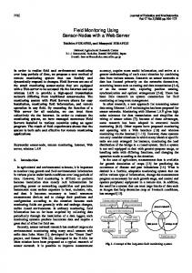
The description of functionality of the file operation routines was concluded by the calculation of their complexity. The complexity of file operations is given as multiples of block read/write operations. To specify the performance, the data throughput of several SD- cards, MCC Cards and MMC Mobile Cards was measured. It turned out that the basic behavior of all cards is the same. The cards differ only in their extreme values. This can be explained by the characteristics of flash memory. Reading flash memory can usually be done in units of single bytes. But to write data the area to be overwritten must be erased beforehand. Such an area is called an erase block. Several erase blocks are usually organized in erase sectors. Several erase sectors are organized in a page. When writing to a SD- card the card controller may need need to erase the block first which takes some time. The card controller uses different erase modes. It can erase a block, a sector, or the whole flash chip. The erase performance differs from flash to flash. But generally erasing the whole flash takes more time than erasing a sector. Erasing a sector takes more time than erasing a block. But in relation to size of the erase area, the speed of erasing the whole flash is much higher than erasing a sector, while this is faster than erasing a block. Not all of these coherences can be found also in figure 7, which shows the performance plot of a 64 MB MMC Mobile Card. The plot contains 50 measurements of reading and writing 100 either sequentially or randomly ordered blocks. The left side of the plot shows the sequential read/write performance. It
can be seen clearly that the reading is relatively constant at a high level of about 430 kByte/sec. The write performance is heavily dependent of the erase strategy of the card controller. The poorest performance usually appears at the first write block (17kByte/sec - 75kByte/sec). The card controllers designed for a PC system provide relatively large caches. Therefore, it assumes to receive several blocks at a time and preerases a sector. This takes some time which leads to the poor write performance of the first block. But most of the following blocks perform much better (96% in a range of 300kByte/sec - 304kByte/sec). The controller seems to be able to do some further optimizations because the plot does not show as much erase cycles as expected of a card with an erase block size of 16kByte. The right side of the plot shows the random read/write performance. As expected the read performance is nearly the same as in sequential mode. The write performance turns out to be much worse (40kByte/sec) than in sequential mode. The card controller has no chance to preerase any areas that are needed for the next block write. The difference between all measured cards are just the extreme values. Read performance was nearly the same for all cards (420 kByte/sec - 440 kByte/sec). This is due to the limited speed of the sensorboard. As described before standard SD- cards are capable of using a serial clock of up to 25 MHz. The sensorboard provided by project Spisa can create a serial clock of about 4.2 MHz. This results from the clock frequency FCY , which is 29.4912 MHz. To set or clear a pin on the sensorboard it needs 2 clocks. One clock for setting the value and a second one for the rise/fall time. So one serial clock period could reach a maximum . But not only the clock but the MOSI pin has of FCY 4 to be set properly. This results in a clock of FCY ≈ 4.2 7 MHz. It is expected that a more performant hardware that comes near the 25 MHz maximum serial clock could reveal differences between the tested cards. Sequential write performance was in average nearly the same for all cards (about 300 kByte/sec). But the minimum throughput ranged from 5kByte/sec to 18 kByte/sec. The larger the cards the lower is their minimum throughput which comes from larger erase block sizes of larger cards. Random write performance depends strongly on the minimum write throughput, which causes smaller cards to be the better choice for embedded systems. Due to this behavior it is strongly recommended to try to optimize any algorithm that uses a SD- card to write at least 2 sequential blocks at a time. This increases the performance to about 160 kByte/sec. Of course many algorithms need to randomly access blocks, but under certain circumstances they can be altered to do a few redundant reads resulting in sequential writes. Writing more than one block at a time is also a matter of RAM, so special solutions for each hardware have to be realized.
4. CONCLUSION The proposed filesystem fulfills all requirements to a memory extension for sensor nodes with sparse resources. It uses a small RAM footprint and allows for random access within a file. The filesystem is used by project Spisa for teaching and research. Applications that use this filesystem are the
sequential read/write (64 MB MMC Mobile Card)
random read/write (64 MB MMC Mobile Card)
500
500
450
↓ read average is 433.9 kiB/s
450
400
↑ read results ↓ write results
400
↓ write average is 303.03 kiB/s
300
↑ read results ↓ write results
350
96.26% 2.02%
throughput [kiB/s]
throughput [kiB/s]
350
↓ read average is 428.2 kiB/s
250
200
3.28% 0.02%
300
250
200
0.78%
150
150
100
0.44%
100
50
↓ write average is 40.6 kiB/s
50
0.94%
16.2% 80.06%
0
↑ write minimum is 17.6 kiB/s 0
20
40 60 80 blocks (512 bytes each)
100
0
120
↑ write minimum is 16.4 kiB/s 0
20
40 60 80 blocks (512 bytes each)
100
120
Figure 7: Read/write performance of the proposed filesystem with a 64 MB MMC Mobile Card . The left plot shows the performance when the blocks are accessed sequentially. The right plot refers to randomly accessed blocks. The right numbers give the percentage of data samples that are located in the marked areas. Whereas the read performance is similar for the sequential and the random case, the write performance is more than seven times worse in average for the random case. software framework of the Spisa sensorboard including file exchange between the PC and the sensor via a serial interface and a camera to take VGA pictures to be stored on the SD- card. In research the filesystem is used for image processing using wavelet and classic compression algorithms. Our future investigations concern the optimization of the filesystem to support lock mechanisms for parallel file accessing. For sensor nodes with extremely sparse resources (≤512 Bytes RAM) the filesystem will provide virtual block sizes. These allow the use of blocks smaller than 512 Bytes and therefore need less RAM for read-modify-write operations. We plan to make the filesystem freely available at [8].
5.
[4]
[5]
[6]
REFERENCES
[1] Chin-Hsien Wu. A flash translation layer for huge-capacity flash memory storage systems. Proceedings of the IEEE/ACS International Conference on Computer Systems and Applications (AICCSA’08), pages 100 – 107, April 2008. [2] S. Jain and Y.-H. Lee. Real-time support of flash memory file system for embedded applications. Proceedings of the Fourth IEEE Workshop on Software Technologies for Future Embedded and Ubiquitous Systems and the Second International Workshop on Collaborative Computing, Integration, and Assurance (SEUS’06/WCCIA’06), April 2006. [3] S.-Y. Kim and S.-I. Jung. A log-based flash translation layer for large nand flash memory. Proceedings of the
[7]
[8]
8th International Conference on Advanced Communication Technology (ICACT’06), 3:1641–1644, Feb. 2006. S.-H. Lim, C. Lee, and K.-H. Park. Hashing directory scheme for nand flash file system. Proceedings of the 9th International Conference on Advanced Communication Technology (ICACT’07), pages 273 – 276, February 2007. Renesas Technology Corp. MultiMediaCard 16 MByte/32 MByte/64 MByte/128 MByte Rev. 5.0, Jan. 2003. available at http://doc.chipfind.ru/renesas/hb28b064mm2.htm. SD Group and Technical Committee SD Card Association. SD Specifications Part 1 Physical Layer Simplified Specification Version 2.00, Sept. 2006. available at http://www.sdcard.org/about/memory_card/pls/. J. Wang and Y. Hu. A novel reordering write buffer to improve write performance of log-structured file systems. IEEE Transactions on Computers, 52(12):1559–1572, December 2003. Wavelet Application Group. Project homepage of Spisa - Signal Processing Intelligent Sensor Applications. http://www.mdt.tu-berlin.de/research/wavelets, 2004-2008.