RFID technologies promise the ability to monitor a va- riety of assets [1â3]. ...... ploy a free space path loss model, where the relationship between the received ...
Facilitating an Active Transmit-only RFID System Through Receiver-based Processing Yu Zhang, Gautam Bhanage, Wade Trappe, Yanyong Zhang, and Rich Howard Wireless Information Network Laboratory Rutgers University, Piscataway, NJ 08854, USA {yu,gautamb,trappe,yyzhang,reh}@winlab.rutgers.edu
Abstract— Many asset tracking applications demand long-lived, low-cost, and continuous monitoring of a large number of items, which has posed a significant challenge to today’s RFID design. In order to satisfy these requirements, we propose to adopt transmit-only tags without a receiver, which can offer both low power and low cost. In spite of their great potential, such a platform faces many challenges since it cannot sense the channel, causing the collisions among tag transmissions to be high. It is thus crucial to employ effective multi-user detection schemes at the tag reader to extract valid information from collided signals. Traditional detection schemes, such as successive cancelation, cannot be directly applied to the targeted system. Firstly, due to the simplicity of receiver-less transmit-only tags, there is no mechanism for feedback to the tags that is traditionally needed for accurate multi-user detection. More importantly, these schemes impose serious processing and memory requirements on the underlying system, which makes real-time tracking impossible. In this study, we address these challenges by performing a statistical estimation of the signal amplitude, and by dividing the received signal sequence (from all the tags) and assigning each block to one reader. We also adopt an online learning mechanism so that readers can anticipate the tags that belong to them. We show that the proposed detection algorithm can achieve low detection error under realistic system conditions.
I. I NTRODUCTION RFID technologies promise the ability to monitor a variety of assets [1–3]. Although RFID technologies have had many success stories, such as the EZ-Pass system for electronic toll collection, the ability for RFID systems to simultaneously monitor a large amount of items, such as would be needed for more tightly managing inventory, while also having low-cost, has continued to be a significant challenge. Ideally, in order for an enterprise to track its assets, it is desirable to identify precisely where individual items are at any moment over an extended period of time. Passive tags that depend on harvesting power from a basestation have performance bounded by the regulatory limits of costly high-power basestations (e.g. on the order
of 4Watts). Alternatively, at lower frequencies they work well, but only for short range (∼ 1 cm) sensing, which cannot provide continual tracking. Active tags overcome many of these limits and provide improved range and reliability. Unfortunately, the standard assumption that such tags would consume a large amount of power has made it impossible to continuously monitor over a period of years. In order to avoid the shortcomings associated with both types of tags, in [4], we proposed to adopt transmit-only active tags, which have the long range of traditional active tags, but without their high power consumption. In a system built on such transmit-only tags, tags periodically announce their presence by sending out their tag IDs, and the processing burden is placed on the tag reader. Since transmit-only tags cannot sense the channel, their transmissions are likely to collide with each other, especially for a system with a large number of tags. Thus, the tag reader must employ effective multi-user detection schemes to extract tag IDs from collided signals. In our earlier work [4], we tested the feasibility of putting together such a system by using several simple detection schemes. While our results in [4] provided some initial support towards building a realistic tracking system using transmit-only tags, the detection accuracy left room for significant improvement, especially for a dense RFID system. To address this need, in this study, we focus on the development of a specialized multi-user detection scheme suitable for transmit-only RFID systems. Our starting point is the popular successive cancelation algorithm. We formulate the successive cancelation algorithm in the context of our random on-off keyed tag signals, and discuss the algorithm for both coherent and non-coherent detection scenarios. As successive cancelation suffers from high computational and memory complexity, which is disadvantageous for real-time asset tracking, we then present an improved detection scheme that significantly reduces resource complexity while maintaining desirable detection performance. We then examine the performance of
1-4244-1268-4/07/$25.00 ©2007 IEEE This full text paper was peer reviewed at the direction of IEEE Communications Society subject matter experts for publication in the IEEE SECON 2007 proceedings.
our tag detection scheme by evaluating it in the context of a broader system. For this system, we make each tag reader responsible for multiple tags, and discuss several approaches to achieve efficient tag handoff between readers. The paper is organized as follows. First, we will examine related work in Section II. Then, in Section III, we introduce our basic RFID system and communication model. Next, in Section IV, we turn to the problem of identifying tags in spite of collisions by using a successive cancelation algorithm that has been customized for our RFID problem. In Section V, we support the feasibility of our approach by providing a scalability analysis, and also propose an algorithm for updating tag lists as tagged items move through the environment. An evaluation is provided in Section VI, and we conclude the paper in Section VII. II. R ELATED W ORK Recently, radio frequency identification has attracted significant research interest [2, 3]. However, in order for RFID to succeed, it is necessary to have low-cost RFID systems that have good performance [3], and thus there has been extensive work to design a low cost tag [5]. One particularly difficult challenge that is faced by RFID tags is the issue of multiple tags transmitting at the same time. For contact-read tags, this issue is not serious, but for noncontact tags, the issue of identifying tags in spite of the potential for collisions is very significant. One approach to handling collisions is to employ a basic CSMA-style medium access control mechanism [6], or other MAC protocol, such as an ALOHA [7–11] strategy. More recently, for tags with receive capabilities, a tree based approach has been explored [12–16]. All of the above methods require the tags to have receive functionality, which inevitably increases the cost and power consumption of a tag. In this paper, we propose to completely remove the receiver from the tag. Rather, each tag transmits periodically, and we place the task of detection and collision resolution on the readers. This is similar to DS/CDMA [17, 18], which allows multiple users transmit simultaneously, and the receiver decodes transmissions via de-spreading. For such systems, there are many detection methods, such as the optimum receiver, MMSE receiver, and successive cancelation methods [18–21]. However, unlike conventional multi-user communications, we do not have a feedback mechanism for power control, as is used in [18–21]. Rather, in this work we estimate which tags are present using a modified successive cancelation method that estimates the amount of tags
present as well as the received signal level at the base station. Recently, [4] introduced a method using derivatives of correlation functions to estimate the transmission times of tags in an RFID system. However, because of near-far problems, the derivative method does not perform well in some cases. To handle these problems, this paper improves upon traditional successive cancelation [17, 18, 20, 21] and the derivative method. III. S YSTEM M ODEL A. RFID System Model A typical RFID system is composed of four components: the tag, the reader, application software that makes use of the data at the reader, and a computer system that is connected by the reader. Similarly, in our model, there are a number of tags. Each tag has a unique identifier of length L (in this paper, we shall use L = 100δ for our discussions, where δ is the time taken to transmit one bit and thus serves as the unit). In general, a proper L is chosen to ensure that the necessary number of tags is far less than 2L . We shall assume that the tags transmit their tag identifiers as beacons in order to support the detection of individual tags, and that the tags transmit periodically with a period of T bits of transmission duration. In order to reduce the collisions, T >> L. On the other hand, T should not be too large, so that real-time detection is guaranteed. A data rate of 1M b/s was chosen as this corresponds to the rate supported by the current generation of low-cost radio chips, giving L = 10−4 sec and we used T = 1 sec for the period. In our paradigm, the communication is one-way and asynchronous, i.e. tags only transmit signals. This greatly simplifies the logic on board a tag, and thus a tag’s cost can be significantly reduced. There are two meanings of asynchronization. First, there is no synchronization between the transmission of tags. Since we need the logic of tags to be simple, we can neither require all tags transmit simultaneously nor in a TDMA manner. Further, the communication between tags and the reader is without synchronization, which implies that, in order to detect each tag, we need to also estimate the transmission time of that tag. The tag reader, which we shall often refer to as a basestation, consists of an RF frontend that downshifts the received waveform to baseband, performs A/D, and supplies an appropriately sampled waveform to a processor for the detection and identification of the tags. The processing of the sampled waveform could be performed on-board (if the reader has a sufficiently powerful DSP/FPGA), or can be performed off-board by a PC (e.g. samples may be
Tag 1 Signal Computer
RFID Tag
∞ N � �
(3)
� fi (di )Ci (t − nT − τi ) cos(φi − φ)/2
i=1 n=0
+ nI (t) ∞ N � �
AIi Ci (t − nT − τi ) + nI (t)
i=1 n=0
For the sake of simplicity and cost-effectiveness, our tags use on-off keying (OOK) as the basic modulation scheme. This choice is motivated by our system implementation effort (which will be reported in a follow-on paper), where we have chosen a radio chip that uses OOK. For tag i, suppose that the transmitting baseband signal is Ci (t), which is a randomly generated sequence composed of 1 or 0. Here, i ∈ {1, . . . , N }, represents the index of the tag, and N is the total number of tags in the system. Since we use OOK modulation, given the carrier frequency ωc and the phase φi , the modulated signal will be Ci (t) cos(ωc t + φi ). Suppose the distance of tag i to the reader is di and the starting time of the transmission is τi , with τi being an integer multiple of the unit δ. In a wireless fading environment, because the tag periodically transmits with period T and T >> L, the received signal for tag i is fi (di ) Ci (t − nT − τi ) cos(ωc t + φi ) (1)
n=0
where fi (di ) is the received amplitude resulting from path loss and the fading of tag i’s signal. Thus, the complete received signal is
where nI (t) is the I-phase filtered Gaussian noise and � AIi = fi (di )cos(φi − φ)/2. Similarly, we can get the Q-phase received signal: � � �� RQ (t) = − LP r (t) sin ωc t + φ� (4) =
N � ∞ �
� fi (di )Ci (t − nT − τi ) sin(φi − φ)/2
i=1 n=0
+ nQ (t) =
∞ N � �
AQi Ci (t − nT − τi ) + nQ (t)
i=1 n=0
where nQ (t) is the Q-phase filtered Gaussian noise and � AQi = fi (di )sin(φi − φ)/2. IV. D ETECTION A LGORITHM Due to collisions, the received signal at the reader during any time interval is the composition of one or more tag signals, as shown in (3). These signals may mask or compromise each other and thus corrupt the detection process. In this section, we explain our strategy and our algorithms to solve the detection problem. A. Detection Strategy
ri (t) + nw (t)
(2)
i=1
=
=
=
B. RFID Communication Model
r (t) =
…
to obtain the demodulated signal � � �� RI (t) =LP r (t) cos ωc t + φ�
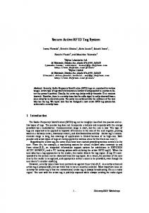
transferred via PCI Express), as depicted in Figure 1. Our objective is to detect the tags in collisions without MAC or synchronization through received-based processing.
∞ �
…
Fig. 2. Tag Signals in Collision.
Fig. 1. RFID System Model.
N �
…
Signals in Collision
Alarm
ri (t) =
…
Tag 2 Signal
RFID Reader
N � ∞ �
fi (di ) Ci (t − nT − τi ) cos(ωc t + φi )
i=1 n=0
+ nw (t) . At the demodulator, we first pass the received signal through a local oscillator, downshift and low-pass filter,
Since the transmission times of these tags are not known, and the received signal at any time may be just a corrupted signal, we will focus on a period T of the received signal as the input for processing. Because tags’ transmissions are periodic, any received signal of duration T contains a complete description of the information needed for detection. In order to detect the N RFID tags, we estimate the signal amplitude for each of the N tags, and decide whether
the estimation is valid. Here, we use a predefined minimum received signal strength of T hreshold and declare the tag is present if the estimated signal strength is no smaller than T hreshold. If the estimation is valid, we declare that the corresponding tag is present. Suppose tags transmit independently, for tag j, the estimation of its received signal amplitude just depends on the received signal at the duration [τj , τj + L). Thus, before the estimation of the signal amplitude, the transmission time of each tag must be estimated. The baseband tag signal is composed of L pulses, each corresponding to either a 0 or 1. For analysis, we assume the pulse p (t) has �δ �δ duration δ, with 0 p (τ ) dτ = 0 p2 (τ ) dτ = 1, and represents a 1. Similarly, a pulse g(t), with the same duration �δ �δ and 0 g (τ ) dτ = 0 g 2 (τ ) dτ = 1 represents a 0. It is straightforward to show that the average autocorrelation of each tag signal is L/2, and that the crosscorrelation of tag signals is L/4. Therefore, we can perform a correlation between the received signal of duration T with each tag signal Cj of duration L. The position of the peak in the correlated signal is the estimated transmission time τˆj . For 0 ≤ t < T , the correlated signal is � ρj (t) = t
N t+L �
Ai Ci (τ − τi ) Cj (τ − t) dτ
(5)
i=1 t+L
�
Cj (τ − t) n (τ ) dτ.
+ t
However, due to collisions, the estimation τˆj may not be accurate, and the estimate only deteriorates further because of near-far issues. A natural solution is to estimate the tag with the maximum signal strength received at the reader, because it is most robust to collisions, and subtract its contribution from the received signal. By repeating this process, as long as the estimation of the received signal strength of each tag is sufficiently accurate, we remove large high-confidence components and amplify the presence of less powerful tags for further processing– a process known as successive cancelation [18]. B. Coherent Detection For analytical simplicity, we first examine a coherent scheme. However, because coherent detection would require an increase in the cost of tags, we will not use it in our system. In coherent detection, we know the carrier phase of each tag. For simplicity, we do not align the phase φˆ of the generated signal from the oscillator to the carrier phase φi . The phase information is used only at the later validation. Suppose the recovered baseband received signal from the I-phase and Q-phase component
Set R0 (t) = R (t), the received signal S0 = {indices of all tags} for k=1 to N Get rˆkmax Rk (t) = Rk−1 (t) − rˆkmax Sk = Sk−1 − kmax end for for k=1 to N Amplitude(r ˆkmax ) if ≥ T hreshold � cos(φi −φ)
Then Tagkmax exists end for
Fig. 3. Successive Cancelation Method for Coherent Detection
for j ∈ Sk ρkj = correlate (Rk−1 � , Cj ) � cj (αj ) = max ρkj , αj ∈ [0, T ) end for cmax (α ˆ kmax ) = argmax cj (α )
j ρk ˆ kmax )− l�=kmax ρk (α ˆ kmax )/[(N −1)] (α k l max ˆk �L 2 A max = 2 0
Ck
max
ˆk rˆkmax = A ˆ kmax ) max Ckmax (t − α
(τ )dτ
Fig. 4. Estimate of rkmax from the residual signal Rk−1 (t).
N ∞ is R (t) = i=1 n=0 Ai Ci (t − τi ) + n (t), which is composed of N tag signals, with a demodulated signal strength of Ai . Successive cancelation finds the tag signal with the maximum signal strength in each step, and subtracts this signal from the received signal, until all the tag signals are found, as shown in Fig.3. S is the set which contains the index of undetected tags. At the first step, S0 will consist of all tags indices. After each iteration, the index of the detected tag will be removed from the set. Fig.4 shows the estimation of both the transmission time and tag signal for the kth round. First, we get the maximum value cj (αj ) of the absolute value of the correlated signal ρkj , where j ∈ Sk−1 . We use absolute value because Ai may be negative due to the phase offset. Next, αkmax ) among all cj (αj ) is obthe maximum value cmax (ˆ tained, which is the maximum value of all the correlations at the kth step. Then, α ˆ kmax is the corresponding estimation of the transmission time of tag kmax , and is the position of the maximum value at the correlated signal ρkkmax . For notational convenience, we assume j = kmax . In a correct detection, α ˆ j = τj . Without considering the noise, � ρkj (τj ) =
τj +L
τj
+
Aj Cj 2 (τ − τj ) dτ
�
|τi −τj |