Far-Field Continuous Speech Recognition System based on Speaker Localization and Sub-Band Beamforming Afsaneh Asaei1, Mohammad Javad Taghizadeh1 and Hossein Sameti2 1 Multimedia Research Group, Iran Telecommunication Research Center, Tehran, Iran 2 Computer Engineering Faculty, Sharif University of Technology, Tehran, Iran E-mails:
[email protected],
[email protected],
[email protected] information by localizing the speaker and forms the array beam pattern directivity towards the speaker. Therefore, it can be useful in various noisy environments. This steering and formation of beam pattern towards different directions is called beamforming. The basic approach of beamforming is attributing a delay to each microphone. The delays correspond to the relative lateness for receiving the farfield sound comparing to a reference microphone. Almost all localization algorithms rely on this delay to find the direction of the speaker. The accuracy of speaker localization has serious effects on the performance of this technique. Various methods have been proposed recently [4] but they all seem to give erroneous estimations in speaker direction finding under the presence of high noise and reverberation and consequently recognition accuracy degrades. This paper proposes a system of Speech Recognition based on speaker Localization and Beamforming (SRLB). To achieve the same gain for all frequency band of speech signal, sub-array design is implemented and speech sub-bands are received via different arrays. Noisy speech segments are then detected and removed from speaker localization to improve robustness and a new method of speaker localization by beamforming algorithm based on periodic structures is implemented. To evaluate the performance of the proposed system, Farsi continuous speech recognition experiments are carried out through various experiments. Part 2 introduces our proposed system. Test scenario and recognition results are presented in part 3 and we conclude on this subject in part 4.
Abstract This paper proposes a Distant Speech Recognition system based on a novel speaker Localization and Beamforming (SRLB) algorithm. To localize the speaker an algorithm based on Steered Response Power by utilizing harmonic structures of speech signal is proposed. This new scheme has the ability of speaker verification by fundamental frequency variation; therefore it can be utilized in the design of a speech recognition system for verified speakers. Then the performance of the Farsi speech recognition engine is evaluated under notorious conditions of noise and reverberation. Simulation results and tests on real data shows that by utilizing proposed localization scheme, recognition accuracy improves by 28% in high noise and reverberant conditions compared to the accuracy of single channel recognition. The capability of this algorithm in localizing a verified speaker improves system robustness to speech noises and reduces recognition errors up to %52 in the presence of speech noise.
1. Introduction Hands-free speech recognition accuracy degrades considerably due to the noise and reverberation. Many techniques have been proposed to improve its performance [1, 2], but most of them strongly depend on the noise characteristics. They work effectively only under constrained conditions [3]. Speech enhancement by microphone array for robust hands-free speech recognition has been seriously considered in recent years. A microphone array consists of multiple spatially arranged microphones and the received signals at each microphone have a phase difference according to the position of sound sources. To achieve the enhanced speech signal, this technique principally utilizes this
978-1-4244-1968-5/08/$25.00 ©2008 IEEE
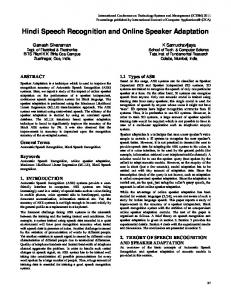
2. System Overview Figure 1 displays the architecture of the recognition system.
495
Voice Activity Detection
Speaker Localization
ratios in between, this algorithm keeps the previous decision [6]. Threshold values are adaptively determined based on the 8 last frames. Algorithm decisions are also followed for successive frames. Detection of one speech frame among several nonspeech frames is erroneous. After the estimation of background noise power from non-speech frames, the frames with power near to noise are removed from the localization algorithm [7].
Speech Recognition
Beamforming
Figure 1. Block diagram of the SRLB system In the SRLB system, microphone array receives audio signal and speaker localization is performed by a novel algorithm based on beamforming. Then enhanced signal is utilized for feature extraction and the recognition engine produces phoneme streams.
2.3. Proposed speaker localization method The proposed speaker localization method is based on Steered Response Power of a beamformer or SRP. In this approach all candidate spatial locations are scanned by microphone array beam pattern steering. Then source location is estimated based on the maximum output power. The output of a general filter and sum beamformer in frequency domain is calculated by equation 1.
2.1. Sub-array design for speech acquisition The microphone array frequency response or beam pattern is a function of the frequency and the distance between microphones. For higher frequencies, smaller array provides the same pattern. Therefore, the speech signal is divided into sub-bands and each band is received from a different array which is called subarray. The number and placement of microphones in each sub-array have important effects on the quality of speech acquisition. Therefore, by investigating the superdirective microphone array designs [5] and regarding spatial non-aliasing rules, a placement of 11 microphones is employed and the speech signal is divided into 5 sub-bands. These sub-bands are summarized in table 1.
M
Y (ω , ∆1 ...∆ M ) ≡ ∑ G m (ω ) S m (ω ) e − jω∆ m
Where ∆1 ,..., ∆ m are steering delays that are computed for candidate locations in space. S m (ω ) is the received signal at microphone m which is filtered by Gm (ω ) . Steered response power is calculated by equation 2. P(∆1 ...∆ M ) ≡ ∑ Y (ω , ∆1 ...∆ M ) Y ′(ω , ∆1 ...∆ M )
Table 1. Speech sub-bands and assigned sub-arrays Microphone Microphone Frequency Band Index Distance Less than 500 1 - 11 500 - 1000 1, 2, 6, 10, 11 20 cm 1000 - 2000 2, 3, 6, 9, 10 10 cm 2000 - 4000 3, 4, 6, 8, 9 5 cm 4000 - 8000
4, 5, 6, 7, 8
(1)
m =1
ω
(2)
Although steering delays are continuous values, equation 2 is calculated for sampled locations in space. In calculating SRP, the choice of a suitable filter has a considerable effect on the robustness of localization to both noise and reverberation. In a familiar algorithm SRP-PHAT, the filter employing at each channel is given by: 1 Gm (ω ) ≡ for m = 1....M (3) X m (ω )
2.5 cm
2.2. Voice activity detection
The proposed filtering scheme is based on the degree of harmonicity measured at speech sub-bands. The mean of squared normalized error Dk at kth harmonic band is calculated between synthesized spectrum S’(ω,ω0) of harmonic bands and the original speech spectrum S(ω) utilizing equation 4.
Speaker localization performance is improved by the detection and removal of non-speech frames from the localization process. To detect the speech frames, the received signal is analyzed regarding stationary or non-stationary properties. Consequently, maximum and minimum power is computed for input signal frames and the ratio of minimum value to maximum is calculated and checked to see if it is above a maximum value for stationary frames. It is assumed to be nonstationary if this ratio is below the threshold value. For
bl
Dl =
∑ ω
2
S (ω ) − S ' (ω , ω 0 )
= al bl
∑ al
496
S (ω )
2
(4)
Where ω0 is pitch frequency, al and bl are the first and last harmonics in the kth band, S(ω) is the original speech spectrum, and S’(ω,ω0) is the reconstructed speech spectrum which is calculated using:
S(ω,ω0 ) = Ak (ω0 )W(ω)
1≤ k ≤ K,
(k − 0.5)ω0 ≤ ω ≤ (k + 0.5)ω0
fundamental frequency and its 10-12 initial components [8]. After speaker localization beamforming is performed by equation 1, therefore, the distortion of amplitude flattening would not be seen in the output signal.
(5)
2.4. Speech recognition
The Synthesized speech spectrum in equation 3 is the multiplication of a constant envelope Ak and excitation spectrum E(ω), where spectrum amplitude Ak is calculated by equation (6) and E(ω) is the spectrum of the Hanning window centered on the frequency of kth harmonic.
The utilized recognition engine is a Farsi continuous phoneme recognizer, where Hidden Markov Model (HMM) is used for modeling of speech phonemes. Modeling is based on continuous density HMMs with Gaussian compositions and only left to right jumping is permitted. An HMM with 6 states is trained for each phoneme and number of compositions is set to 16. The procedure to optimize the model structure is described in detail in [8]. The system input is a speech signal and the output is a stream of phonemes that well matches the acoustic input stream. This system is speaker independent. Speech frames are 20 ms with 60% overlapping. The vector of extracted features contains 12 Mel-Cepstrum coefficients and its first and second differentials. HMMs topology is the same for all phonemes. Farsdat database is used for experiments, which contains 6080 Farsi words in 405 sentences spoken by 304 speakers. This database is recorded under low noise environment with an average SNR of 31dB. 140 sentences are used for tests while the remains are used in the training process.
( k + 0 .5 ) ω 0
A k (ω 0 ) =
∑
S (ω )W (ω )
( k − 0 . 5 ) ω 0 ( k + 0 .5 ) ω 0
∑
(6)
W (ω )
2
( k − 0 . 5 ) ω 0
The estimated error from equation (4) represents the degree of harmonicity of each sub-band of speech spectrum and is utilized in exploiting a filtering scheme for localization algorithm. The proposed filter for each channel is:
Gk,m(ω) =
1− Dk,m | Sm (ω)|
, ω∈[(k −0.5)ω0,(k +0.5)ω0]
(7)
Using this filter, the voiced speech frames will have more effect on localization than noisy speech frames. Furthermore, by removing the influence of signal amplitude, phase information is used for localization. In practice, it is enough to estimate fundamental the frequency harmonics for only reference microphone of the array when array dimension is small. By employment of the proposed filter in beamforming algorithm, steered response power of the array is calculated by equation (8) and localization is based on maximum output power. The proposed method is named SRP-H as it is based on beamforming and analyses speech signal regarding fundamental frequency harmonics. M K 1− D ~ k,m Y(ω, ∆1...∆M ) ≡ ∑∑ Sm (ω) e− jω∆m S ( ω ) m=1 k=1 m
3. Experimental results Figure 2, shows source position in front of the microphone array. Our simulation test room is 4 × 6 × 4 m3 and signal sources are at the same level of the linear array.
(8)
In this equation K represents the number of harmonics in 4 KHz frequency band and M is the number of microphones. Empirically, Localization accuracy does not change noticeably for the value of K greater than 10. It could be the result of energy distribution of speech signal mostly around the
Figure 2. Microphone placement and source position in simulated scenario
Room acoustic is simulated by Image method [9], for different reflection coefficients corresponding to
497
T601 = {0, 0.27s, 0.47s}. Signal to noise ratio at the reference microphone is simulated for SNR = {5dB, 15dB}. In order to localize the speaker, the microphone array signal is processed in 25ms frames with 50% overlapping. The input signal is up-sampled to 96 KHz, which increases the accuracy as we are now able to compute 0.23 sub-sample corresponding to one degree precision in space scanning. Figure 3 shows percentage of anomalies in direction estimation for different signal to noise ratios in high reverberant environments.
Figure 4. SNR improvement after localization and beamforming (SL + BF) and localization and sub-band beamforming (SL + Sub_BF) The vertical axis is SNR improvement after beamforming. Horizontal axis shows original input SNR. It can be concluded from these experiments that due to the design of sub-arrays which results in achieving similar beam pattern for the entire speech frequency band, noise effect is reduced considerably. The enhanced signal is then utilized for feature extraction and phoneme recognition. This experiment is achieved in the presence of white and colored noises where colored noise is created by employing a low pass filter on white noise to suppress the frequency under 800 HZ. As the array beam pattern has the least directionality (almost no) in these frequencies, using this filter shows the most influence of localization and beamforming on system performance. Table 2 shows Phoneme Accuracy Rate2 or PAR for different noise and reverberation conditions.
Figure 3. Anomaly percentage of location estimation by SRP, SRP-H and SRP-PHAT vs. different SNRs, T60 = 0.47s It can be seen that SRP-PHAT shows low performance in low SNR conditions due to removal of amplitude effects. The proposed algorithm SRP-H by removing the influence of destroyed frames based on detection of periodic structures shows 10% fewer anomalies compared to SRP-PHAT in high reverberant high noisy conditions. It also shows that SRP-PHAT and SRP-H performs much better than SRP in noisy conditions. The performance is improved by the proposed method, but it enforces computation overhead of pitch estimation which can be reduced considerably by a fast preliminary pitch estimation algorithm and tracking. Therefore, it can be implemented at real-time and is capable of speaker tracking with good accuracy results. After the estimation of speaker position, the time delays for the microphone signals are set such that the beam pattern directivity forms towards the source and speech sub-bands are received from assigned subarrays. SNR improvement of output signal with respect to a single channel (reference microphone) is represented in figure 4.
Table 2. Recognition accuracy in the presence of color noise 0
5 0.27
0.47
0
15 0.27
0.47
36
22
7
40
25
15
9
-2
-18
18
7
-4
41
32
11
45
36
27
68
50
27
77
55
30
SNR (dB) T60 (s) 1. Single (%PAR) 2. BF (%PAR) 3. BF + SL (%PAR) 4. Sub_BF + SL (%PAR)
2
PAR is calculated by the following equation: PAR = (Number of all recognized phonemes – Number of erroneously inserted phonemes – Number of erroneously deleted phonemes - Number of erroneously replaced phonemes) / (Number of all phonemes)
1 This Parameter shows the time last that normalized impulse response power reduces by 60dB.
498
The first row is phoneme recognition accuracy of a single channel signal. Comparing other rows with this one represents the influence of location information on performance improvement of the proposed speech recognition system. In the second row all microphone signals are summed together and localization is not performed. Negative values mean that the number of phonemes which are erroneously inserted, deleted or replaced is greater than the number of all recognized phonemes. Result of this part shows array front gain. It can be seen that recognition accuracy degrades considerably. This reduction is greater when no reverberation exists because we do not have any copy of signals received from the main lobe direction. The third row shows recognition results after localization and beamforming. The whole speech band is received from all of the microphones. It can be seen that because of beam pattern variation at different frequencies some of the noise is received from side lobes. Sub-array design and sub-band beamforming improves these results considerably. That is shown in the fourth row. Results of these experiments under white noise are presented in table 3.
speaker localization and beamforming is an effective method but is not enough in high reverberant environments and dereveberation algorithms should be utilized to recover the signal from channel effects.
3.1. Verified Speaker Speech Recognition The proposed localization method employs fundamental frequency harmonics; therefore it can be used for speaker verification utilizing this information. In this procedure, after the fundamental frequency is exploited, a verification algorithm tests it for certification of authorized speaker and then localization is only performed for the passed speech frames. This experiment is achieved when two people start to speak simultaneously. In this scenario the fundamental frequency is exploited when only one of them is speaking. Frames with overlapping speech do not keep any periodicity and can not be used in pitch detection algorithms. After pitch is determined, the frequency is compared with a threshold value and localization is performed for those within the accepted range. This method can reduce the speech-like noises within the SRLB system. Table 4 presents recognition results in the presence of human speech noise before and after localization and beamforming. Two scenarios of testing are presented regarding the speakers’ sound Level Ratios (LR). One is a condition in which both speakers speak at the same level and in the second the undesired speech level is one fifth of that of the desired sound. Explanations are the same as that of table 2. It can be seen that multi-channel speech enhancement by utilizing location information of the speakers can reduce false recognition in the presence of speech noises and recognition accuracy is improved up to 52% in highly reverberant environment.
Table 3. Recognition accuracy in the presence of white noise
0
5 0.27
0.47
0
15 0.27
0.47
39
14
2
48
16
6
48
20
3
51
24
17
73
34
13
81
39
22
SNR (dB) T60 (s) 1. Single (%PAR) 2. BF + SL (%PAR) 3. Sub_BF + SL (%PAR)
Because the noise signal has important coefficients in low frequencies, these coefficients appear in the output of the beamformer due to less beam pattern accuracy at these frequencies. This problem can be solved by the use of a bigger array to sharpen the main lobe of the beam pattern at low frequency bands and reduce the noise components at low frequencies by accurate beamforming. The usefulness of a bigger array is due to providing a sub-array with greater distance between the microphones to create a sharper gain lobe at low frequencies [5]. Comparing SNR improvement results with the recognition accuracy it can be concluded that considerable SNR improvement due to design of subarray, greatly increases recognition accuracy. Reverberation however has an important effect on our recognition engine performance. This effect can not be seen in experimental results on SNR improvement. Therefore multichannel speech enhancement utilizing
Table 4. Speech recognition in the presence of speech noise and verified speaker localization
T60 (s)
0
1 0.27
0.47
0
0.2 0.27
0.47
1. Single(%PAR)
-4
-9
-16
58
39
33
2. BF (%PAR)
13
-21
-26
13
12
7
3. BF + SL (%PAR)
2
-2
-6
65
44
37
4. Sub_BF + SL (%PAR)
7
3
-1
75
64
59
LR
499
4. Conclusion
5. Acknowledgement
This paper proposes a distant, Farsi, continuous Speech Recognition system based on Speaker localization and Beamforming by microphone array. This system is tested under different noisy and reverberant conditions. In this system, multi-channel speech enhancement based on beamforming is used in a localization algorithm. In order to achieve a similar beam pattern for all frequency bands, the designed microphone array consists of five nested sub-arrays where each sub-band is received from the assigned array. Then all the subbands are joined to make the output which is used in feature extraction. Experimental results present recognition accuracy improvement by utilizing the information of the speaker location with subband beamforming. These results present that the Farsi continuous speech recognition accuracy improves up to 28% comparing to that of single channel signal and 45% if no localization is performed. This shows the importance of localization and noise reduction by the beamforming algorithm. The proposed method has the ability to verify the speaker based on fundamental frequency information. To achieve this capability the algorithm runs the localization process only when the exploited fundamental frequency is verified and stops updating location finding at other times. Therefore, the array beam pattern remains unchanged for non-valid speech data regardless of the noise type. This new capability is addressed for the first time in distant talking speech recognition systems. As it was experimented, this method improves accuracy rates (up to 52%) of the SRLB system in the presence of high reverberation. This algorithm also stops the localization updating process when both of the speakers are talking and the received speech data loss its periodic nature. By developing this method through speaker verification and identification algorithms it will be possible to use the system for authorized speakers which can be useful for applications like command recognition. Because this system is based on short data segments, it can track and lock on a speaker and is also expected to have the capability to be employed in speech recognition applications when the speaker walks while talking. In order to perform robust recognition in high reverberant environments, dereveberation techniques usually based on blind deconvolution should be considered.
The Authors wish to express their gratitude to Dr. M. Shahram Moin, leader of the multimedia research group in Iran Telecommunication Research Center for his support.
6. References [1] [2] [3]
[4]
[5] [6] [7]
[8]
[9]
500
S. F. Boll, “Suppression of acoustic noise in speech using spectral subtraction”, IEEE Trans. ASSP-27, April 1979, pp. 11- 120 A. P. Varga, and R. K. Moore, “Hidden Markov Model decomposition of speech and noise”, ICASSP90, April 1990, pp. 845-848 T. B. Hughes, H. Kim, J. H. DiBiase, and H. F. Silverman, “Performance of an HMM speech recognizer using a real-time tracking microphone array as input”, IEEE Trans. on Speech Audio proc. 7(3): 346-349, May 1999 A. Asaei, H. Sameti, "Speaker Direction Finding for Practical Systems: A Comparison of Different Approaches", Proceeding of the third Annual IEEE BENELUX/DSP valley signal processing symposium, Metropolis, Antwerp, Belgium, March 2007, pp 129133 W. Tager, “Near field superdirective (NFSD)”, ICASSP98, 1998, pp 2045-2048 A. M. Kondoz, Digital speech coding for low bit rate communication systems, Wiley Pulisher, 2004 A. Asaei, H. Sameti, M. H. Moin, "Robust Speaker Localization by Beamforming Algorithm Exploiting a New Fillter Based on Periodic Structures, proceedings of The 12th International Conference CSI Computer Conference (CSICC'07) , Feb. 2007, pp 55-60 Veisi H., Fazel A., Hosseinzadeh Kh., Sameti H., "Robust Recognition in Farsi Continuous Speech Recognition Engine, Farsi Continuous Speech Recognition Project", Report No.1-3, Reported to Ministry of Industrial and Mines Department for High Tech Industrials, Tehran-Iran, Oct. 2004 J. B. Allen and D. A. Berkley, “Image Method for Efficiently Simulating Small Room Acoustics”, J. Acoust. Soc. Am., vol. 6, no. 4, April 1979, pp. 943-950