phase resolution at a beat frequency of 100 kHz or higher drops below 0.1 deg. .... We got a prospect that the measurement with an angular resolution of ⤠0.1 ...
1998 ICPP&25th EPS Conf. on Contr. Fusion and Plasma Physics, Praha, 29 June - 3 July. ECA Vol. 22C (1998) 1482-1485.
FARADAY ROTATION DENSITOMETRY FOR LHD H. Murayama1, T. Harada2, E. Sato1, S. Tsuji-Iio1, R. Shimada1, M. Takahashi3 , K. Terai3, A. Ejiri4, K. Tanaka5 , Y. Nagayama5, and K. Kawahata5 1
Research Laboratory for Nuclear Reactors, Tokyo Institute of Technology 2-12-1 O-okayama, Meguro-ku, Tokyo 152-8550, Japan, 2
Shimadzu Corporation, 3 Toshiba Corporation, 4 University of Tokyo, and 5National Institute for Fusion Science Abstract
A polarimeter which measures the Faraday rotation of a CO2 laser beam in LHD plasmas is being developed to back up interferometry. An accurate measure of the rotation angle would enable us to monitor the electron density in LHD, where confining magnetic field can be computed at least for low plasma pressure. Frequency-shifted heterodyne techniques are applied to a tangential optical layout on the midplane. Preliminary tests without plasma indicate that the phase resolution at a beat frequency of 100 kHz or higher drops below 0.1 deg. with a time resolution of 10 ms.
1. Introduction The electron density is one of the most important parameters which represents the confinement performance. Therefore, the measurement of it in nuclear fusion devices requires both the accuracy and the reliability. Interferometry is a widely used method for the electron density measurements. However, it has a problem with respect to reliability because of “fringe jump". The Faraday rotation angle in a magnetically confined plasma gives the line integral of the electron density times the magnetic field component parallel to the probing beam. In helical devices such as Large Helical Device (LHD), the internal magnetic field in low β plasmas is almost determined by the currents in the external magnetic field coils. Therefore, the electron density can be monitored by measuring the Faraday rotation angle (polarimetry). By this method, real-time measurement is possible and suitable for long-time discharges of LHD. In addition, it also has an advantage over interferometry of immunity against vibrations of devices along the beam path. Due to these reasons, it is expected as a substitution or backup for interferometry. However, the Faraday rotation angle is generally so small that the improvement of the angular resolution is required when a short-wavelength beam is adopted to avoid refraction effects. In this article, a preliminary study and tests for desinging the Faraday rotation densitometer for LHD are described.
1482
1998 ICPP & 25th EPS CCFPP ----- Faraday Rotation Densitometry for LHD
2. Determination of probing laser The approximate expression for the Faraday rotation angle α in magnetically confiened plasmas is as follows: Z −13 2 α = 2.62 × 10 λ ne Bk dl [rad] (1) where λ is the wavelength of the probing beam, ne is the electron density and Bk is the magnetic field component parallel to the probing beam. Eq. (1) means that the Faraday rotation angle is proportional to the square of the wavelength. Although large rotation is desirable for measurement, the longer wavelength is used, the larger refraction in plasma makes the measurement difficult. Therefore, the determination of the wavelength of probing beam is very important for good measurement.
0.15 : nmax 2 : nmax(1-S2)2 : nmax(1-S2)3 : nmax(1-S2)4 : nmax(1-S2)5 : nmax(1-S )
3 2 1 0
inner edge
3
Displacement (mm)
Faraday rotation (deg.)
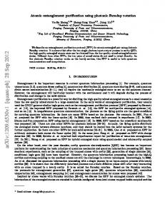
We made numerical calculations where the three-dimensional helical configuration of LHD is taken into account and estimated both the Faraday rotation angle and the deviation by refraction in plasma for different wavelengths of the probing beam. From this result, we choose a CO2 laser as the beam source since the wavelength (10.6 µm) of it is nearly optimum for LHD plasmas in respect that the Faraday rotation angle is measurable (∼ 2 degrees through the plasma center) and that the refraction in plasma is sufficiently small (≤ 0.15 mm). Figures 1 and 2 are examples of the results for CO2 laser (10.6 µm) and shows the spatial profiles of the Faraday rotation angle and the beam displacement by the refraction in LHD plasma under the condition of a central magnetic field Bt (0) = 3 T and several electron density profiles ne = nmax(1 − S)i where i is an integer, nmax the central electron density (1 × 10²⁰ m−3 ) and S the normalized flux radius, respectively.
center of plasma
4
0.1
0.05
0 outer edge
Tangent radius (m)
: nmax 2 : nmax(1-S2)2 : nmax(1-S2)3 : nmax(1-S2)4 : nmax(1-S2)5 : nmax(1-S )
inner edge
3
center of plasma
4
outer edge
Tangent radius (m)
Figure 1. Faraday rotation angle as a function
Figure 2. Beam displacement due to refraction
of tangent radius in an LHD plasma for different electron density profiles.
in an LHD plasma.
Generally, this type of line-integrated measument requires many chords to evaluate local quantities. However, it is not always realistic due to the limitation on diagnostic ports or optical components. If we prepare two chords (for example, one is through the center of plasma and the other more inner chord), the Faraday rotation measurements could give some information on the electron density profile from Fig. 1. 1483
1998 ICPP & 25th EPS CCFPP ----- Faraday Rotation Densitometry for LHD
3. Optical layout The optical layout under study similar to one proposed by Jobes [1, 2] is shown in Fig. 3. In order to improve the resolution of measurements, we adopted the frequency-shifted heterodyne method [3].
laser
ω0
ωb1 AOM AOM
ωb2
ω0+ωb1 ω0+ωb2
polarizer
detector
detector
(reference)
(signal)
ωb
H:ω0+ωb1 V:ω0+ωb2
R:ω0+ωb1 L:ω0+ωb2
ωb=ωb1−ωb2 polarizer
combiner 1/2 wave plate 1/4 wave plate plasma
retro-reflector Figure 3. Schematic optical layout.
Firstly, the beam from the CO2 laser beam is split by a half mirror into two and their frequencies are slightly and differently shifted by two acousto-optic modulators (AOM). After the polarization plane of one of the two beams is rotated by 90◦ with a half wave plate, both beams are combined together again. Then, a quarter wave plate makes them two counterrotating circularly polarized beams at different shifted frequencies. They pass through the plasma tangentially on the equatorial plane and return to the coming path at a retro-reflector in the vacuum vessel. This makes the beam path twice and correspondingly doubles the Faraday rotation angle with only one required diagnostic port. Finally, the beams are square-law detected with the reference and signal detectors. As a result, four times the Faraday rotation angle is detected. In practice, the total Faraday rotation angle includes that through the vacuum window. However, since the helical magnetic field produced by superconducting magnets is maintained almost constant in LHD and the vertical field makes no influence on the Faraday effect of the vacuum window, it will be just an offset and extracted easily from the acquired data. In this layout, the Faraday rotation angle is detected as a change in the phase between the signals from reference and signal detectors at the frequency which is the differece (beat) of the shifted frequencies, which is under testing with a half wave plate mounted in a programmable rotator with an accuracy of 0.01◦ to simulate the Faraday effect in a plasma. As shown in Fig. 3, the beam paths of two counter-rotating circularly polarized beams are basically the same. Therefore, this method doesn’t suffer from the vibrations of optical components unlike interferometry and brings a great advantage for construction of the optical system.
1484
1998 ICPP & 25th EPS CCFPP ----- Faraday Rotation Densitometry for LHD
4. Tests and results As described in the previous section, the Faraday rotation angle corresponds to the phase difference between the signals from reference and signal detectors. Therefore, the tests for checking the accuracy of phase-difference measurements were made in advance. In the test, we arranged the same optical parts as in Fig. 3 on a bench except that no plasma was included and the beam path was short compared to that for LHD. The output power of the CO2 laser (MPB Technologies Inc., Model GN-802GES) was about 6 W. We used a lock-in amplifier (EG&G Princeton Applied Research Model 5302) and measured the standard deviations of the phase output, which determine the angular resolutions, varying the time constant of the lock-in amplifier and the beat frequency.
Standard deviation (deg.)
The results are summarized in Fig. 4. We got the standard deviation of ±0.08 deg. un1 der the condition for the beat frequency of not 10 kHz 0.8 lower than 100 kHz and time constant of not 100 kHz 200 kHz shorter than 10 ms. This means that the mea0.6 400 kHz 800 kHz surement with an angular resolution of ≤ 0.1 0.4 deg. and a time resolution of ∼ 10 ms is pos0.2 sible at worst. However, this is not enough for 0.08 deg. our goal of accuracy, which is the measuement 0 0.1 1 10 100 1000 of three singnificant digits, that is, angular resTime constant of lock-in amplifier (ms) olution on the order of 0.01 deg. In this test, the angular resolution appeared to be determined Figure 4. Standard deviation of phase output as a by not optical layout but the performance of function of the time constant of lock-in amplifier for the lock-in amplifier. We intend to improve different beat frequencies. the angular resolution by some digital signal processing.
5. Conclusions A preliminary study and tests for desining Faraday rotation densitometer for LHD was described. It was shown that CO2 laser is nearly optimum for LHD with respect to both measurable Faraday rotation angle and sufficiently small refraction. The optical layout based on the frequency-shifted heterodyne method was considered to raise the resolution of the Faraday rotation angle. We got a prospect that the measurement with an angular resolution of ≤ 0.1 deg. and a time resolution of ∼ 10 ms is possible at worst.
References [1] F.C. Jobes and D.K. Mansfield: Rev. Sci. Instrum. 63, 5154 (1992). [2] F.C. Jobes: Rev. Sci. Instrum. 66, 386 (1995). [3] G. Dodel and W. Kunz: Infrared Phys. 18, 773 (1978). 1485