Abstract. The Booster of the ANKA synchrotron light source, delivering 10 mA at 500 MeV, is fully operational since. December 1999 [1]. To accelerate 10 mA up ...
FAST FEEDBACK LOOP FOR BEAM LOADING COMPENSATION IN THE ANKA BOOSTER F. Pérez. Forschungszentrum Karlsruhe, Projekgruppe Errichtung ANKA Postfach 3640, D-76021 Karlsruhe, Germany S.P. Møller, L. Praestegaard, J.S. Nielsen. ISA, Aarhus University, Denmark
Abstract The Booster of the ANKA synchrotron light source, delivering 10 mA at 500 MeV, is fully operational since December 1999 [1]. To accelerate 10 mA up to 500 MeV, a simple 200 W solid state amplifier providing up to 30 kV in one cavity was considered to be sufficient [2]. However, at injection, with a reduced RF power from the generator, the induced beam voltage in the cavity is larger than the generator voltage, which means that the system is under a heavy beam loading and only 4 mA could be accelerated. To counteract this strong beam loading effect a Fast Feedback Loop (FFL) [3] was implemented. After the installation of the FFL we were able to accelerate 2.5 times more current, reaching more than the 10 mA goal. In this paper we will explain its implementation and the obtained results in the ANKA Booster.
oscillations of the six 3-GHz injected bunches into one 500 MHz RF bucket. These longitudinal oscillations are transformed into transverse oscillations due to the finite dispersion. The beam induced voltage of a 15 mA injected beam into the cavity is of the order of 45 kV. That is around 10 times larger than the desired voltage in the cavity, which brings the system into heavy beam loading conditions. For that reason the total accelerated beam was less that 4 mA, even though we could inject more than 15 mA (see figure 2, green triangles curve). At that point, the necessity to implement a Fast Feedback Loop was mandatory.
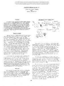
3 FAST FEEDBACK LOOP The scheme of the implemented Fast Feedback Loop is shown in figure 1, following references [3,6].
1 INTRODUCTION The Synchrotron Light Source ANKA is under commissioning since December 1999 [4], when the ANKA booster was fully operational, delivering more than 10 mA at 500 MeV. The commissioning of the ANKA booster started in June 1999. One of the main problems to reach the beam current specifications was the fast beam loading instabilities during the process of injection. To cope with this problem we implemented a simple and cheap Fast Feedback Loop.
2 INJECTION The injection of the 3-GHz bunched microtron beam in the booster is made with a multi-turn injection scheme with a closed-orbit bump over the whole circumference of the booster [5]. After injection, the beam is bunched at the RF frequency of the booster, which is 500 MHz. Everywhere in the booster, the dispersion function is non-zero. These facts make the energy acceptance of the booster during the process of injection very small. In order to have an acceptable injection efficiency, the RF voltage at injection had to be reduced to around 5 kV. The reason is that we need to match the RF bucket to the injection energy acceptance to avoid large longitudinal
1996
Directive Coupler
Pickup
Variable Attenuator Amplitude Loop
Power Coupler
Amplifier o
180 Phase shifter RF Drive
Variable Attenuator
Cavity
Amplifier Gain K
Combiner
Figure 1. Fast Feedback Loop (grey boxes) implemented in the ANKA Booster RF system. The idea is to pickup a sample of the voltage in the cavity and, after proper amplification, combine it, 180° dephased, with the driving signal of the amplitude loop. In this case the total voltage in the cavity, at the resonance frequency, is given by [6]: Vcavity
§��
Vdrive / α������9EHDP���.α
where K is the gain of the amplifier and α is the portion of the cavity signal fed to the feedback loop. This equation tells us that the feedback reduces the induced beam voltage in the cavity by a factor Af = Kα,
Proceedings of EPAC 2000, Vienna, Austria
i.e. the gain of the feedback loop. In addition, the generator voltage is reduced by a factor α. To maintain the same voltage in the cavity, the drive power has to be increased by a factor Kα. To adjust the gain of the feedback loop, we installed a fix gain amplifier with a variable attenuator at the input. To adjust the phase, we use a remotely controlled mechanical phase shifter. The parameters of the feedback loop are given in table I. Table I. Fast feedback loop parameters. Amplifier Gain K 44 dB α
-20 dB
Feedback Gain
Af
24 dB
16
According to the table we have reduced the beam loading voltage in the cavity by a factor 16, but at the same time the drive power has been increased by 24 dB. This was the margin we had in our low level part. To further increase the feedback gain we could have added an extra amplifier, but because this gain was enough for our purposes we stopped there.
4 RESULTS
20
I [mA]
15 FFL ON
10 5 0 -100 0
10 FFL OFF
5
RF Voltage [kV]
RF Voltage 15
0 100 200 300 400 500 600 Time [ms]
Figure 2. Beam current and RF voltage during the acceleration from 50 MeV to 500 MeV Both curves show a fast decay of the beam current in the first hundred milliseconds. We assume that this is due to the fact that the 3-GHz injected beam enters the booster into 500-MHz RF buckets. The result is that half of the bunches are lost due to an excessive energy deviation due to the wrong phase with the RF voltage
Proceedings of EPAC 2000, Vienna, Austria
FFL ON (3)
8 RF OFF (1) 4
FFL OFF (2)
0
Figure 2 shows the accelerated beam from 50 MeV to 500 MeV with and without the fast feedback loop. The RF voltage at injection is around 5 kV. After 100 ms, it is linearly ramped up to 16 kV in around 200ms, and stay constant until extraction at 580 ms. 20
12 I [mA]
Pickup signal
The beneficial effect of the fast feedback loop is seen in the total amount of current finally accelerated: 10 mA versus 4 mA, with and without FFL respectively. Hence an increase in current of almost a factor of 3. The effect of the feedback loop is to reduce the beam loading instabilities at the very beginning of the injection, i.e. during the first microseconds. We could not do measurements at such short time scale, but the effect can be deduced from figure 3, where we compare the beam current during the first milliseconds after injection for three cases: 1) without RF voltage; 2) with RF voltage and the FFL off, and; 3) with RF voltage and the FFL on.
-1
0
1
2
3
4
5
Time [ms]
Figure 3. Captured beam current for three cases: 1) RF off; 2) RF on, FFL off; 3) RF on, FFL on. Our reference curve is the injected beam, given by the beam current when the RF is off (pink squares). We can observe that when the feedback is off, the captured beam current is half the injected one (green triangles). On the other hand, when we switch on the feedback loop, the captured beam remains almost the same as the injected one (blue rhombus). Differences between the two previous figures are due to the fact that the data were taken at two different runs. The data in figure 3 was measured with a not fully optimised microtron beam. Figure 2 is the case for the optimised system.
5 CONCLUSION The beam loading at injection, which gave problems to capture all the injected beam, has been reduced successfully with the implementation of a Fast Feedback Loop.
1997
REFERENCES [1] L.Praestegaard et al, “Commissioning of the ANKA Injector”, this conference. [2] D. Einfeld, F.Pérez, A.Fabris, M. Svandrlik, “RF System for the ANKA Booster Synchrotron”, EPAC 98, p. 1764. Stockholm,. [3] F. Pedersen, IEEE Trans. on Nucl. Science NS22, p1906, 1975. [4] D. Einfeld et al. “Commissioning of the ANKA Synchrotron Light Source”, this conference. [5] D. Einfeld et al. “The injector for the synchrotron light source ANKA”. PAC 99, p. 2427. New York. [6] A. Gamp, “Servo Control of RF Cavities under Beam Loading”, CERN 92-03, 1992.
1998
Proceedings of EPAC 2000, Vienna, Austria