[16] Kishore Andra, Chaitali Chakrabarti and Tinku Acharya,. âA VLSI Architecture for Lifting-Based Forward and. Inverse Wavelet Transformâ IEEE Transaction ...
International Journal of Computer Applications (0975 – 8887) Volume 51– No.6, August 2012
Fast Implementation of Lifting based 1D/2D/3D DWTIDWT Architecture for Image Compression M. Nagabushanam
S. Ramachandran
Anna University Coimbatore, India
SJB Institute of Technology Bangalore, India
ABSTRACT Technological growth in semiconductor industry have led to unprecedented demand for faster, area efficient and low power VLSI circuits for complex image processing applications. DWT-IDWT is one of the most popular IP that is used for image transformation. In this work, a high speed, low power DWT/IDWT architecture is designed and implemented on ASIC using 130 nm Technology. 2D DWT architecture based on lifting scheme architecture uses multipliers and adders, thus consuming power. This paper addresses power reduction in multiplier by proposing a modified algorithm for BZFAD multiplier. The proposed BZFAD multiplier is 65% faster and occupies 44% less area compared with the generic multipliers. The DWT architecture designed based on modified BZFAD multiplier achieves 35% power saving and operates at frequency of 200 MHz with latency of 1536 clock cycles for 512x512 images. The 3D-DWT architecture is designed for 8x8x8 video frame, based on fast lifting scheme approach using (9, 7) wavelet filter. Using 9/7 filter for DWT computation reduces the hardware complexity, memory accesses and achieves minimum error in reconstruction of images. The proposed architecture systematically combines hardware optimization techniques to develop a flexible DWT architecture that has high performance and is suitable for portable, high speed, low power applications. 3D-DWT architecture has been implemented on Virtex-5 FPGA with utilization of 1,152 out of 19,200 (5%) slice registers and the frequency of operation is 256 MHz. The designed DWT-IDWT can be used as IP Core.
Keywords DWT, Image compression, BZFAD multiplier, FPGA, Lifting scheme
1. INTRODUCTION The wavelet transformation is a widely used technique for image processing applications. Unlike traditional transforms such as the Fast Fourier Transform (FFT) and Discrete Cosine Transform (DCT), the Discrete Wavelet Transform (DWT) holds both time and frequency information, based on a multiresolution analysis framework. This facilitates improved quality of reconstructed picture for the same compression than is possible by other transforms. In order to implement real time Codec based on DWT, it needs to be targeted on a fast device. Field Programmable Gate Array (FPGA) implementation of DWT results in higher processing speed and lower costs when compared to other implementations such as PCs, ARM processors, DSPs etc. The Discrete wavelet transform is therefore increasingly used for image coding [1-4]. This is because the DWT can decompose the signals into different sub-bands with both time and frequency information and facilitate to arrive a high compression ratio
[5]. It supports features like progressive image transmission (by quality, by resolution), ease of compressed image manipulation, region of interest coding, etc. The JPEG 2000 incorporates the DWT into its standard [6]. Recently, several VLSI architectures have been proposed to realize single chip designs for DWT [7-10]. Traditionally, such algorithms were implemented using programmable DSP chips for low-rate applications or VLSI application specific integrated circuits (ASICs) for higher rates. To perform the convolution, we require a fast multiplier which is crucial in making the operations efficient. Anirban Das, Anindya Hazra, and Swapna Banerjee [11] have proposed the architecture of the lifting based running 3-D discrete wavelet transform (DWT), which is a powerful image and video compression algorithm. Chin-Fa Hsieh, Tsung-Han Tsai, Neng-Jye Hsu, and Chih-Hung Lai [12], proposed a novel, efficient VLSI architecture for the implementation of one-dimension, lifting-based discrete wavelet transform (DWT). Both folded and the pipelined schemes are applied in the proposed architecture, where the former scheme supports higher hardware utilization and the latter scheme speeds up the clock rate of the DWT. Jen-Shiun Chiang, and Chih-Hsien Hsia [13] have proposed a highly efficient VLSI architecture for 2-D lifting-based 5/3 filter discrete wavelet transform (DWT). The architecture is based on the pipelined and folding scheme processing to achieve near 100% hardware utilization ratio and reduce the silicon area. The proposed efficient 2-D lifting-based DWT VLSI architecture uses lossless 5/3 filter and pipelined processing. The architecture may have almost 100% hardware utilization. The advantages of the proposed DWT are higher hardware utilization, less memory requirement, and regular data flow. The architectures discussed above are suitable for FPGA implementation. In this work, we propose a modified 3D architecture based on 9/7 filter that can operate at high frequency and consume low power. Section 2 presents the lifting based DWT. Section 3 and 4 discuss the arithmetic blocks of DWT and BZ-FAD multiplier respectively. The proposed architectural details of 1D/2D DWT-IDWT are presented in Section 5. Section 6 presents 3D DWT architecture. The results are presented in Section 7. This is finally followed by Conclusion.
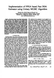
2. LIFTING BASED DWT SCHEME The top level architecture for 1D DWT is presented in Fig. 1a and Fig. 1b. Input X is decomposed into multiple sub bands of low frequency and high frequency components to extract the detailed parameters from X using multiple stages of low pass and high pass filters. The sub band filters are symmetric and satisfy orthogonal property. For an input image, the two 1D DWT computations are carried out in the horizontal and vertical directions to compute the two level decomposition. The inverse DWT process combines the decomposed image
35
International Journal of Computer Applications (0975 – 8887) Volume 51– No.6, August 2012 sub bands to original signal. The reconstruction of image is possible owing to the symmetric property and inverse property of low pass and high pass filter coefficients.
di1 = α (x2i + x2i+2) + x2i+1
...(1)
ai1
...(2)
Input x (n1, n2) is decomposed to four sub-components YLL, YLH, YHL and YHH. This results in a one level decomposition. The YLL sub-band component is further processed and is decomposed to another four sub-band components, thus forming two-level decomposition. This process is continued as per the design requirements till the requisite quality is obtained. Every stage of DWT requires LPF and HPF filters with down sampling by 2. Lifting based DWT computation is widely being adopted for image decomposition. In this work, we propose a modified architecture based on BZFAD multiplier [14, 15] to realize the lifting based DWT.
The first equation is predict P1 and the second equation is update U1. Then the second lifting step is performed resulting in equations (3) and (4):
Lifting scheme is one of the techniques that is used to realize DWT architecture [12]. Lifting scheme is used in order to reduce the number of operations to be performed by half and, filters can be decomposed into further steps in lifting scheme. The memory required and also computation is less in the case of the lifting scheme. The implementation of the algorithm is fast and inverse transform is also simple in this method. The block diagram for lifting scheme [12] is shown in Fig. 2.
b Figure 1 Image Decomposition 1D
di1-1)
+ x2i
di2 = γ (ai1 + ai1+1) + di1
...(3)
ai2
...(4)
= δ
(di2 +
di2-1)
+
ai1
The third equation is predict P2 and the fourth equation is update U2. Thereafter the scaling is performed in order to obtain the approximation and detail coefficients of DWT as given in equations (5) and (6). ai = ζ ai2 = G1 di =
di2
∕ ζ = G2
....(5) ....(6)
The equations (5) and (6) are respectively scales G1 and G2. The predict step helps determine the correlation between the sets of data and predicts even data samples from odd. These samples are used for updating the present phase. Some of the properties of the original input data can be maintained in the reduced set also by construction of a new operator using the update step. The lifting coefficients have constant values of 1.58613, -0.0529, 0.882911, 0.44350, -1.1496 for α, β, γ, δ, ζ respectively. It may be observed by these equations, that the computation of the final coefficients requires 6 steps. Data travels in sequence from stage 1 to stage 6, introducing 6 units of delay. To speed up the process of computation, modified lifting scheme is proposed and realized.
3. ARITHMETIC BUILDING BLOCKS FOR LIFTING SCHEME IMPLEMENTATION
a
a
= β
(di1 +
b 2D
High–speed multiplication has always been a fundamental requirement of high performance systems. Multiplier structure is one of the processing elements which consumes the maximum area, power and also causes delay. Therefore, there is a need for high-speed architectures for N-bit multipliers with optimized area, speed and power. Multipliers are made up of adders in order to reduce the Partial Product logic delay and regularize the layout. To improve regularity and compact layout, regularly structured tree with recurring blocks and rectangular-styled tree by folding are proposed at the expense of complicated interconnects [16]. The present work focuses on multiplier design for low power applications such as DWT by rapidly reducing the partial product rows by identifying the critical paths and signal races in the multiplier. The focus of the design has been to optimize the speed, area and power of the multiplier that form the major bottleneck in lifting based DWT [17] .
3.1 Shift and Add Multiplier Figure 2 Lifting scheme for 1D-DWT using 9/7 filter The z-1 blocks are for delay; α, β, γ, δ, ζ are the lifting coefficients and the shaded blocks are registers. 9/7 filter has been used for implementation, which requires four steps for lifting and one step for scaling. The input signal x i is split into two parts: even part x2i and odd part x2i+1. Thereafter, the first step of lifting is performed given by the equations (1) and (2).
In shift and add based multiplier logic, the multiplicand (A) is multiplied by multiplier (B). If the register A and B storing multiplicand and multiplier respectively are of N bits, the shift and add multiplier logic requires two N bit registers, an N bit adder and an (N+1) bit accumulator. It also requires an N- bit counter to control the number of addition operation. In shift
36
International Journal of Computer Applications (0975 – 8887) Volume 51– No.6, August 2012
Figure 4 Low power multiplier architecture [14, 20] Figure 3 The Architecture of the Conventional Shift-and-Add Multiplier and add logic, the LSB bit of multiplier is checked for 1 or 0. If the LSB bit is 0, then the accumulator is shifted right by one bit position. If the LSB bit is 1, then the multiplicand is added with the accumulator content and the accumulator is shifted right by one bit. The counter is decremented for every operation; the addition is performed until the counter is set to zero, which is indicated by the Ready signal. The product is available in the accumulator after N clock cycles. Fig. 3 shows the block diagram of the conventional multiplier using shift and add logic, which generates a partial product (PP). B(0) is generally used to select A or 0 as is appropriate.
4. Modified BZ-FAD Multiplier As discussed in shift and add logic earlier, if the LSB position is 1, then the accumulator is added with the multiplicand. If the accumulator contains more number of 1s than 0s, the adder has to add 1 and, this triggers the Full adder block within the adder. We know that the power dissipation is due to switching activity of input lines. Thus, whenever the input or output changes, the power is switched from Vdd to Vss, thus consuming power. In order to reduce the power dissipation, it is required to reduce switching activity in the I/O lines. BZ-FAD logic based multiplier [15] reduces the switching activity and thus reduces the power dissipation. In shift and logic operation, the counter keeps track of the number of cycles, thus controlling the multiplication operation. In a binary counter, we know that the output bit change occurs in more than one bit. For example, if the current counter value is 3 (11 in binary) and changes to 4 (binary 100), there are three bit changes occurring. This causes switching activity, and the same can be reduced by replacing the binary counter by a ring counter. In a ring counter, at any given point of time, only one bit change occurs, thus reducing switching activity and power dissipation.
the same as right shift operation. The architecture of this multiplier is shown in Fig. 4. In the BZ-FAD, the control activity of ring counter, latch and bypass logic is realized using NMOS transistors, which introduces delay. The parasitic capacitance of NMOS transistors also increases the load capacitance and thus increases power dissipation. In order to reduce power dissipation, the transistor logic is replaced by MUX logic having ideal fan in and fan out capacitances. With MUX based logic, the control signals can be suitably controlled to reduce the switching activity as they are enabled only when required, based on the inputs derived from the ring counter. However, the design requires more number of transistors than it should and thus increases the chip area. We have also used the ripple carry adder which has the least average transition per addition among the look ahead, carry skip, carry-select and conditional sum adders to reduce power dissipation. Various multipliers are modeled in HDL and are analyzed for their performances and the results are tabulated for comparison. Next section discusses the comparison results of these multiplier algorithms [18].
4.1 COMPARISON MULTIPLIER
RESULTS
OF
In this section, comparison of power, area for different types of multipliers using modified multiplier (BZ-FAD) is presented. The results reveal that the modified BZ-FAD multiplier may be considered as a low-power, yet area efficient multiplier. Table 1 Power comparison of the proposed BZ-FAD multiplier with other multipliers
Another major source of power dissipation in shift and add logic is switching. For every bit value “0” of the multiplier, a shift operation is performed; thus all the bits in the accumulator are shifted by one bit position. This causes switching and hence more power is dissipated. In BZ-FAD logic, if the LSB bit is 0, then the shift operation is bypassed and a zero is introduced at the MSB, thus there is no shifting of accumulator content. In other words, if the LSB is zero, the accumulator is directly fed into the adder and there is no addition, but a zero is introduced by the control logic which is
37
International Journal of Computer Applications (0975 – 8887) Volume 51– No.6, August 2012 width. This leads to a small increase in the leakage power which, as the results reveal, is less than the overall power reduction. The leakage power of the 8-bit BZFAD architecture is about 11% more than that of the conventional architecture but the contribution of the leakage power in these multipliers is less than 3% of the total power for the technology used in this work. It may be noted that since the critical paths for both architectures are the same, neither of the two architectures has a speed advantage over the other [19-23].
5. Discrete wavelet transform and Inverse Discrete wavelet transform implementation Figure 5 Power comparisons of multipliers The power consumption of the multipliers for normally distributed input data are reported in Table 1. As can be seen in Fig. 5, the BZ-FAD multiplier consumes 33% lower power compared to the conventional multiplier. The results reveal that the BZ-FAD multiplier is a very low-power, yet highly area efficient multiplier. In terms of the area, the proposed technique has some area overhead compared to the conventional shift-and-add multiplier as shown in Fig. 6 and Table 2. Comparison of Fig. 3 with Fig. 4 reveals that multipliers M1, M2 and the ring counter are responsible for additional area in the proposed architecture. The area overheads of the ring counter and multiplexers M1 and M2 scale up linearly with the input data
Table 2 Area comparison of proposed multiplier with other multipliers [19, 20, 21]
DWT has traditionally been implemented by convolution. Such an implementation demands both a large number of computations and a large storage features that are not desirable for either high-speed or low-power applications. Recently, a lifting-based scheme that often requires far fewer computations has been proposed for the DWT [24-27]. The main feature of the lifting based DWT scheme is to break up the high pass and low pass filters into a sequence of upper and lower triangular matrices and convert the filter implementation into banded matrix multiplications. Such a scheme has several advantages, including “in-place” computation of the DWT, integer-to-integer wavelet transform (IWT), symmetric forward and inverse transform, etc. Therefore, it comes as no surprise that lifting has been chosen in the upcoming implementations. The proposed architecture computes multilevel DWT for both the forward and the inverse transforms: one level at a time, in a row-column fashion. There are two row processors that compute the high pass and low pass filter outputs as shown in Fig. 1. Four column processors operate on the row processed outputs. The outputs generated by the row and column processors divide the input image into four sub bands of LL, LH, HL and HH. These sub bands are stored in the memory modules for further processing. The memory modules are divided into multiple banks to accommodate high computational bandwidth requirements. The proposed architecture is an extension of the architecture for the forward transform that was presented earlier. A number of architectures have been proposed for calculation of the convolution-based DWT. The architectures are mostly folded and can be broadly classified into serial architectures, where the inputs are supplied to the filters in a serial manner and, parallel architectures, where the inputs are applied to the filters in a parallel manner. A design methodology for lifting based DWT has been evolved by us that reduces the memory requirements and communication among processors when the image is broken up in to blocks. For a system that consists of the lifting-based DWT transform followed by an embedded zero-tree algorithm, a new interleaving scheme that reduces the number of memory accesses has been proposed. Finally, a liftingbased DWT architecture has been developed as shown in Figure 7, which is capable of performing filter operation with one lifting step, i.e., one predict and one update step. The outputs are generated in an interleaved fashion.
Figure 6 Area comparisons of multipliers [19, 20, 21] Figure 7 2-D Lifting-based DWT
38
International Journal of Computer Applications (0975 – 8887) Volume 51– No.6, August 2012 The lifting scheme is represented by the following equations of the 1-D DWT: h(i) =x(2i+1)+α(x(2i)+x(2i+2))
…(7)
l(i)=x(2i)+β(h(i)+h(i-1))
…(8)
The 2-D DWT is a multilevel decomposition technique that decomposes into four sub bands such as hh, hl, lh and ll. The mathematical formulae governing the 2-D DWT are as follows: hh(i, j) = h(2i +1, j) +α (h(2i, j) + h(2i + 2, j))
…(9)
hl(i, j) = h(2i, j) + β (hh(i, j) + hh(i −1, j))
…(10)
lh(i, j) = l(2i +1, j) +α (l(2i, j) + l(2i + 2, j))
…(11)
ll(i, j) = l(2i, j) + β (lh(i, j) + lh(i −1, j))
…(12)
Similary, the 2-D IDWT is defined as follows: l(2i,j)
= ll(i,j)-β(lh(i,j)+lh(i-1,j))
…(13)
l(2i+1,j) = lh(i,j)-α(L(2i,j)+l(2i+2,j))
…(14)
h(2i,j)
…(15)
= hl(i,j)-β(hh(i,j)+hh(i-1,j))
h(2i+1,j)= hh(i,j)-α(h(2i,j)+h(2i+2,j))
…(16)
x(i,2j)
…(17)
= l(i,j)-β(h(i,j)+h(i,j-1))
x(i,2j+1) = h(i,j)-α(x(i,2j)+x(i,2j+2))
…(18)
The Discrete Wavelet Transform and the Inverse Discrete Wavelet Transform Core have been coded in Verilog and synthesized using Synopsys Design Compiler. The two RTL Cores operate at a maximum clock frequency of 200 MHz. The design of DWT and IDWT are checked for testability. The timing and power reports are obtained using the Primetime. The architectures for DWT and IDWT perform in (4N2 (1−4− j ) + 9N)/6 computation time, where N is number of samples. The total power consumption of the DWT/IDWT processor is ~0.367mW. The area of the designed architecture using 0.13 micron technology is 112 X 114 µmm2, and the maximum frequency of operation reported is 200 MHz for Discrete Wavelet Transform. For the IDWT, whose architecture is presented in Fig. 8, the area and the maximum frequency reported is 112 X 114 µmm2 and 200 MHz respectively.
application. Flexible hardware architecture is designed for performing 3D Discrete Wavelet Transform. The proposed architecture uses new and fast lifting scheme which has the ability of performing progressive computations by minimizing the buffering between the decomposition levels. The 3D wavelet decomposition is computed by applying three separate 1D transforms along the coordinate axes of the video data. The 3D data is usually organized frame by frame. A single frame has rows and columns as in the 2D case, x and y direction often denoted as “spatial co-ordinates”, whereas for the video data, a third dimension of “time” is added (zdirection). The input data is a set of multiple frames each consisting of N rows and N columns. Hence the input data can be denoted as NxNxN, where N is an integer. The 3D DWT can be considered as a combination of three 1D DWT in the x, y and z directions as shown in Fig. 9. A preliminary work in the DWT processor design is to build 1D DWT modules, which are composed of high-pass and low-pass filters that perform a convolution on filter coefficients and input pixels. After a one-level of 3D discrete wavelet transform, the volume of frame data is decomposed into HHH, HHL, HLH, HLL, LHH, LHL, LLH and LLL signals as shown in Fig. 9. The arithmetic blocks adopted in the design of 1D/2D DWT are extended to the design of 3D DWT as well. One of the major changes in the 3D architecture is the intermediate memory stages that are required for reordering of 1D and 2D output samples for the computation of 3D samples. Fig. 10 shows the 3D architecture with intermediate memories. For
6. 3D DWT Architecture Design and VLSI implementation of high speed, low power 3D wavelet architecture is targeted on video coding
Figure 9 One-level 3D DWT structure
Figure 8 2-D Lifting based IDWT Table 3 Area and Power Report of DWT Synthesis Report
Area (mm2) Power (w)
Without BZ-FAD
With BZ-FAD
(Shift and add multiplier)
multiplier
20654 572
21984 367
Figure 10 3D DWT architecture using intermediate memory
39
International Journal of Computer Applications (0975 – 8887) Volume 51– No.6, August 2012 the computation of 3D-DWT, 1D-DWT has been performed first on the video frame data of size 8x8x8 data sets. Input data are fed to the first stage of the DWT, where the 8 bit shift register is used. It reads data from the memory and applies serial data into the DWT module. The first stage of the DWT is a split stage, where it divides the input data into even and odd samples. The next stage of the DWT is the predict stage. The even samples are multiplied by the predict factor and the results added to the odd samples to generate the detailed coefficients. These coefficients are computed by the predict step, multiplied by the update factors and are added to even samples to get the coarse coefficients. This process is continuous.
7. Simulation and Place & Route Results The 3D DWT simulation results using ModelSim is presented in Fig. 11. The 8 sub level images are discernible from the figure. The HDL model developed is synthesized using Xilinx ISE targeting Virtex-5 FPGAs. 3D-DWT architecture has been implemented on Virtex-5 FPGA with the utilization of 1152 slice registers and the reported maximum operational frequency is 256 MHz. The designed DWT can be used as an IP Core for VLSI implementation.
8. CONCLUSION In this work, low power architecture for shift-and-add multipliers has been proposed and implemented. The conventional architecture has been modified by removing the shift operation of the B register (in A × B), direct feeding of A to the adder, and bypassing the adder whenever possible. It also uses a ring counter instead of the conventional binary counter and removes the partial product shifter. The BZ-FAD multiplier is further modified using multiplexers and XOR gates. The modified multiplier is modeled and implemented using 130 nm technology. The modified multiplier is used in constructing lifting based DWT/IDWT architecture. The DWT/IDWT architecture is modeled and synthesized using TSMC libraries. The BZ-FAD multiplier based DWT/IDWT architecture reduces power dissipation by 30% and operates at 200 MHz. The adders in the lifting based DWT/IDWT can be further improved by replacing the adders by low power adders. 3D-DWT architecture has been implemented on Virtex-5 FPGA utilizing 1152 slice registers and reporting a maximum frequency of operation of 256 MHz. The developed DWT can be used as an IP for VLSI implementation. The 1D/2D/3D DWT use large numbers of intermediate memories. In order to reduce the memory size, systolic array architectures may be adopted. Power dissipation can be reduced using low power design techniques. 3D DWT can
also be implemented as an ASIC, optimizing for area, power and speed.
REFERENCES [1] Tze-Yun Sung, Hsi-Chin Hsin Yaw-Shih Shieh and Chun-Wang Yu, “Low-Power Multiplierless 2-D DWT and IDWT Architectures Using 4-tap Daubechies Filters”, Seventh International Conference on Parallel and Distributed Computing, Applications and Technologies, December 2006. [2] Abdullah AL Muhit, Md. Shabiul Islam and Masuri Othman, “VLSI Implementation of Discrete Wavelet Transform (DWT) for Image Compression”, 2nd International Conference on Autonomous Robots and Agents, 13-15 December 2004. [3] Motra A. S. Bora P.K. and Chakrabarti I., “An efficient hardware implementation of DWT and IDWT”, Conference on Convergent Technologies for Asia-Pacific Region, 15-17 October 2003. [4] Yun-Nan Chang and Yan-Sheng Li, “Design of highly efficient VLSI architectures for 2-D DWT and 2-D IDWT”, IEEE Workshop on Signal Processing Systems, 26-28 September 2001. [5] Keshab K. Parhi and Takao Nishitani, “VLSI architectures for discrete wavelet transforms”, IEEE Transactions on Very Large Scale Integration Systems, Vol. 1, No. 2, pp. 191-202, June 1993. [6] David S. Taubman, Michael W. Marcellin, “JPEG 2000Image compression, fundamentals, standards and practice”, Kluwer academic publishers, Second Edition, 2002. [7] Simone Borgio, Davide Bosisio, Fabrizio Ferrandi, Matteo Monchiero, Marco D. Santambrogio, Donatella Sciuto and Antonino Tumeo, “Hardware DWT accelerator for MultiProcessor System-on-Chip on FPGA”, Embedded Computer Systems: Architectures, Modeling and Simulation, 2006. IC-SAMOS 2006, July 2006, pp. 107 - 114. [8] Mel Tsai, BDTI, “Designing Processing Systems”,
Low-Power
Signal
http://www.dspdesignline.com/showArticle.jhtml?article ID=187002923. [9] Tze-Yun, “Low-power and high-performance 2-D DWT and IDWT architectures based on 4-tap Daubechies filters”, Proceedings of the 7th WSEAS International Conference on Multimedia Systems and Signal Processing, Hangzhou, China, pp. 50-55, 2007. [10] S. Baloch, I. Ahmed, T. Arslan, A. Stoica, “Low power domain-specific reconfigurable array for discrete wavelet transforms targeting multimedia applications, “International Conference on Field Programmable Logic and Applications”, pp. 618-621, International Conference on Field Programmable Logic and Applications, 2005. [11] Anirban Das, Anindya Hazra, and Swapna Banerjee, “An Efficient Architecture for 3-D Discrete Wavelet Transform”, IEEE Transactions on circuits and systems for video technology, Vol. 20, No. 2, February 2010.
Figure 11 ModelSim simulation results for 3D DWT
[12] Chin-Fa Hsieh , Tsung-Han Tsai , Neng-Jye Hsu , and Chih-Hung Lai, “ A Novel, Efficient Architecture for
40
International Journal of Computer Applications (0975 – 8887) Volume 51– No.6, August 2012 the 1D, Lifting-Based DWT with Folded and Pipelined Schemes” Department. of Electronics Engineering, China Institute of Technology, Taipei, Taiwan and Department. of Electrical Engineering, National Central University, Chung-Li, Taiwan, IEEE Trans 2004. [13] Jen-Shiun Chiang, and Chih-Hsien Hsia, “An Efficient VLSI Architecture for 2-D DWT using Lifting Scheme,” IEEE International Conference on Systems and Signals, pp. 528- 531, April 2005, Taipei, Taiwan. [14] Kuan-Hung Chen and Yuan-Sun Multiplier with the Spurious Technique,” IEEE Trans. on Integration (VLSI) Systems, Vol. pp. 846-850.
Chu, “A Low-Power Power Suppression Very Large Scale 15, No. 7, July 2007,
[15] M. Mottaghi-Dastjerdi, A. Afzali-Kusha, and M. Pedram BZ-FAD: A Low-Power Low-Area Multiplier Based on Shift-and-Add Architecture, IEEE Transactions on Very large Scale Integration systems, Vol. 17, No. 2, Feb. 2009. [16] Kishore Andra, Chaitali Chakrabarti and Tinku Acharya, “A VLSI Architecture for Lifting-Based Forward and Inverse Wavelet Transform” IEEE Transaction on signal processing , Vol. 50, No. 4, pp. 966-977, April 2002. [17] Movva S and Srinivasan S, “A novel architecture for lifting-based discrete wavelet transform for JPEG2000 standard suitable for VLSI Implementation” VLSI Design, 2003 Proceedings, 16th International Conference 4-8, Jan. 2003, pp. 202 – 207, Washington, DC, USA. [18] Dusan Suvakovic, C. Andre, Salama, “A Pipelined Multiply-Accumulate Unit Design for Energy Recovery DSP Systems”, IEEE International Symposium on Circuits and Systems, May 28-31, 2000. [19] Jung- Yup Kang, Jean-Luc Gaudiot, “A Simple HighSpeed Multiplier Design”, IEEE Transactions on computers, Vol. 55, No. 10, October 2006, pp. 12531258.
[20] Zhijun Huang, Milos D. Ercegovac, “High-performance Low-power Left-to-Right Array Multiplier Design”, IEEE Transactions on computers, Vol. 54, No. 3, Mar. 2005, pp. 272 – 283. [21] C. S. Wallace, “A Suggestion for a Fast Multiplier”, IEEE Trans. computers, Vol. 13, No. 2, pp. 14-17, 1964. [22] Vojin G. Oklobzija, Bart R. Zaydel, Hoang Q. Dao, Sanu Mathew and Ram Krishnamurthy, “Comparison of highperformance VLSI adders in the energy-delay space”, IEEE Trans. VLSI Systems, Vol. 13, No. 6, pp. 754-758, June 2005. [23] J-Y Kang and J-L Gaudiot, “A Fast and Well structured Multiplier,” EUROMICRO Symposium on Digital System Design, pp. 508 – 515, Aug. 2004. [24] Nagabushanam, M., Cyril prasanna Raj, and Ramachandran, S., “Modified VLSI implementation of DA-DWT for image compression”, International Journal of Signal and Imaging Systems Engineering (to be published by Inderscience, swizerland, in feb2013). [25] Nagabushanam, M., Cyril Prasanna Raj and Ramachandran, S., “Design and implementation of parallel and pipelined distributive arithmetic based discrete wavelet transform IP core’, EJSR International Journal, Vol. 35, No. 3, pp. 379–392, 2009. [26] Nagabushanam, M., Cyril Prasanna Raj, and Ramachandran, S., “Design and FPGA implementation of Modified Distributive arithmetic based DWT-IDWT processor for image compression”, International Conference on Communication and Signal Processing, February, NIT, Calicut, India, 2011. [27] Nagabushanam, M. and Ramachandran, S., “Fast Implementation of Lifting based DWT Architecture for Image Compression”, Global Journal of Computer Science and Technology (F), Volume – XII, Issue XI, Version I, pp. 23-29, June 2012.
41