IEEE TRANSACTIONS ON MAGNETICS, VOL. 50, NO. 1, JANUARY 2014
1401004
Fast Moving Multiple Magnetic Bits in Permalloy Cylindrical Nanowires Feng-Sheng Wu, Lance Horng, and Jong-Ching Wu Department of Physics, National Changhua University of Education, Changhua 500, Taiwan Controlling the movement of domain walls in magnetic nanowires is important due to the impact on the viability of data storage devices. A series of micromagnetic simulations of multiple current-induced domain walls motion (CIDWM) have been performed. Multiple CIDWM in the cylindrical permalloy nanowires display outstanding dynamic properties. In cases of different domain bits, we observed the motion of transverse domain walls (TDWs) did not show oscillatory behavior. The domain walls only changed their positions in the same direction as they propagated and kept the distance between the walls almost the same, with their internal magnetic structure unchanged. Furthermore, we have found that the TDW velocity in cylindrical thin wires was closely related to the wire thickness and showed a strong dependence on the Gilbert damping factor. Index Terms— Magnetic domain walls, magnetic memory, micromagnetics.
I. INTRODUCTION
A
GROWING number of innovative concepts has been proposed which uses domain walls in nanowires as information bits for memory [1] or logic devices [2]–[4]. In particular, the potential of a memory shift register based on DWs called the Racetrack Memory [5], [6] is highly attractive since it has the practicability of replacing current silicon based memories as well as magnetic hard disk drives. It is a nano-sized magnetic wire where 10 to 100 bits of information are stored as magnetic domains. Pulses of electric current move the magnetic domain walls rapidly along the racetracks for reading and writing data. For utilizing magnetic domain-wall displacement along a cylindrical nanowire [2], [7], one of the fundamental issues is the precise control of DW motion. Exploring and defining the controlled movement of domain wall (DW) in magnetic nanowire injected by short pulses of spin-polarized current has been the subject of intensive study in recent years [8]–[10]. In order to either read or write one bit, the targeted bit has to be moved to the reading or writing device, respectively. To do so, all the data bits, i.e., all the DWs, have to be moved together under the influence of a single current pulse, so that the targeted bit reaches the reading or writing element without disturbing the other stored bits. Two challenges need to be overcome here: one is that to depin the DW and to initiate the DW motion requires a high critical current density; the other is that the Walker breakdown phenomenon, caused by deformations in the magnetic nanostructures, limits the DW velocity [11]–[13]. More recent publications, however, offered a promising solution indicating that a transverse domain wall in a thin, round nanowire is not subject to the situations found in a flat strip. The reason is that the TDW in a cylindrical nanowire displays exceptional properties: massless DW, zero depinning current, the absence of the Walker breakdown [14]–[16].
In this paper, we focus primarily on whether multiple TDWs can be translated in nanowires with promptness and on analysis of main influence factors, such as the applied current, the damping factor and the wire thickness, aiming to discover their distinctive attributes and potential applications to data storage devices. Agreeable results obtained show that multiple CIDWM in thin cylindrical nanowires are most likely to be a desirable candidate for nanosized devices based on domain-wall propagation. The velocity of TDWs in a cylindrical nanowire simply depends linearly on the current density. It can be observed that TDWs behave like massless structures, i.e., these domain walls with no magnetic structural transformations only change their positions in the same direction as they propagate and keep the distance between the walls almost the same. Consequently, there is no Walker breakdown in the case of the cylindrical nanowires. A. Methods Our micromagnetic simulations using the LLG code [17] were performed by integrating the Landau-Lifshitz-Gilbert (LLG) equation of motion in a 1000 nm long cylindrical nanowire with cell size of nm . The simulations started from initial domain walls artificially created in nanowires, where the applied current was initially zero ( A) and then the polarized current were injected. The velocity of the walls was determined by averaging out the sum of individual domain wall speed over a duration of 5000 ps from the steady-state motion. To get a picture of how the domain walls behave, it is necessary to review the LLG equation of motion for a magnetic moment as follows [18], [19]:
(1) This equation is identical to the modified Landau-Lifshitz-Gilbert (LLG) equation [22]
Manuscript received April 26, 2013; revised June 29, 2013; accepted July 23, 2013. Date of current version December 23, 2013. Corresponding author: F.-S. Wu (e-mail:
[email protected]). Color versions of one or more of the figures in this paper are available online at http://ieeexplore.ieee.org. Digital Object Identifier 10.1109/TMAG.2013.2274758 0018-9464 © 2013 IEEE
(2)
1401004
IEEE TRANSACTIONS ON MAGNETICS, VOL. 50, NO. 1, JANUARY 2014
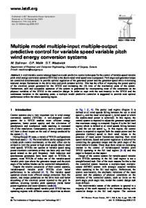
Fig. 1 (color online) Schematic description of a spiral structure within a propagating TDW showing the magnetization and the domain wall width in a 15 nm diameter cylindrical wire. Cross sections suggest the position of the wall plane in a continuous sequence, while the white arrows stand for the orientation of the transverse magnetization.
which is equal to the usual LLG equation in the limit of where and , with as the local magnetization, the saturation magnetization, the gyromagnetic ratio, the effective field, the Gilbert damping factor, and the coefficients and given by and , with being the current density applied in the positive x direction, the electron charge and the degree of polarization of the spin current. is generally called the spin drift velocity and is actually the maximum velocity that the DW can reach when the conduction electron spin moments are fully converted into DW displacement. The dimensionless coefficient characterizes the nonadiabatic contribution which is 0.04 in our simulations. The material parameters were those typical of permalloy: A/m, zero anisotropy, and exchange constant A/m, . The applied magnetic field was zero for all the simulations presented in this paper. As we further investigate (2), the first two terms are from magnetization variation in time and the last two describe the magnetization variation in space. Interestingly, the first two terms are independent of the current. The last two terms represent the current-driven effect since they are proportional to the current. The first and second terms respectively describe the precession and the relaxation due to the effective field, which does not contribute to the time evolution of the DW. The time evolution of the DW is shown to be completely due to the terms induced by the electric current, namely, the third (nonadiabatic torque) and fourth (adiabatic torque) term in (2). B. Results The simulated configuration of one of the transverse walls in a magnetic wire is exhibited in Fig. 1, which shows the sketch in a cylindrical wire with diameter 15 nm and a TDW is placed at the center of the wire. In order to apply current-induced spin transfer torque, we have injected current in the positive x-direction where electrons flow in negative x-direction. The DW was displaced by the electrical current along towards the direction, namely, in the electron flow direction. In Fig. 2(a), we presented a sample of the parallel TDWs in a cylindrical nanowire under our simulation and took a snapshot of one of them. According to our simulation it is clear that the TDW widths in the cylindrical nanowires are kept almost the same throughout the wires, and their general shapes remain unchanged across all trials. To make a comparison to the TDW in a cylindrical nanowire, we also simulated on antivortex DWs in
Fig. 2 (color online) (a) Images from micromagnetic simulations showing the transverse DW configurations in a 15 nm diameter cylindrical nanowire. (b) Images from micromagnetic simulations showing the antivortex DW configuranm nanostrip. (c) TDW width is defined to be the region tions in a between the dashes where the component of the long-axis magnetization is less of the value in the bulk of the wire. than
a nm nanostrip and took a snapshot of one of them as shown in Fig. 2(b). We observe that the DW undergoes continuous changes in its configuration while propagating in a nanostrip, which differs from that in a cylindrical nanowire. The current-driven DWs were not all moving towards the direction of electron flow, with some DWs even moving towards the opposite direction. Such antivortex DWs were accompanied by the interaction between different types of energy and unstable structural transformation. It can be deduced that the two features are the leading causes of the breakdown-like behavior for the DWs motion in the strip case. The spin-density waves, which are caused by spin-polarized currents, emitted from domain walls can affect the domain-wall magnetization dynamics. They are similar to an external magnetic field and have a relatively strong effect on the motion of the domain wall [20], [21]. However, in the case of a spin-density wave, the effective field acting on the domain walls is not homogeneous. On the contrary, it is strongly oscillating. The oscillatory spin waves which induce some fluctuating displacements and certain disorder of the walls are on a par with the exchange and anisotropy energies controlling the shape and dynamics of the domain walls. This is consistent with what is demonstrated in the previous paragraph and provides a further explanation for the cause of the breakdown-like behavior of DWs in a nanowire. However, based on our simulation, the fluctuating displacements caused by the oscillatory spin waves were not observed from the multiple CIDWM in cylindrical nanowires. We have performed micromagnetic simulations to find the motion of multiple TDWs shown in Fig. 3. A sequent time evolution of images of TDWs displacement is exhibited. It displays 3 bits, i.e., two walls, in a cylindrical nanowire with diameter 15 nm as a function of time by a constant polarized current ( A), from top to bottom. The arrows indicated that the TDWs began to enter a stable mode (512 ps). According to the
WU et al.: FAST MOVING MULTIPLE MAGNETIC BITS IN PERMALLOY CYLINDRICAL NANOWIRES
1401004
Fig. 3 (color online) Three bits in a 1000 nm long, 15 nm diameter permalloy cylindrical nanowire as a function of time by a constant polarized current A), from top to bottom. (
results of micromagnetic simulations for various current densities, we obtained several important characteristics of these multiple domain walls. First, the TDWs moved together as soon as the current was applied without disturbing the other stored bits. Second, the velocity of TDWs in a cylindrical nanowire was almost a constant which was proportional to applied current density. Third, their structures did not undergo any deformation during the propagation. Because of the axial symmetry, the structures of the walls and their energy were invariant with respect to rotations of the magnetization in the yz plane. Consequently, there was no Walker breakdown in the case of the cylindrical nanowires. This behavior was consistent with the absence of mass and inertia of the walls. In this paper, we studied the velocity of TDWs, which was computed for multiple transverse DWs by micromagnetics as function of the current density A/m . Our simulations were performed for different numbers of bits (2, 3 bits per nanowire). was determined by averaging out the sum of individual domain wall speeds based on displacement required over a duration of 5000 ps after the DWs motion entered a stable mode. To obtain a related physical understanding of the simulated data, we adopt an analytical model developed in [15], [22], and [23]. From (1), we express in spherical coordinates where radial distance, polar angle, azimuth angle and x is chosen as the polar axis. Equation (1) with , static magnetic field H applied along the direction, we can obtain
(3) (4) denotes the DW center. These equawhere the subscript tions present how the adiabatic term affects the linear motion of the DWs. The linear velocity is basically equal to the spin drift velocity as we get from (3). This indicates the DW velocity is proportional to both the charge current density and the DW width . Also, it can be seen that the nonadiabatic parameter almost has no effect on the DW velocity, which is
Fig. 4 (color online) Comparison of the DWs velocity among the 10, the 15 and the 20 nm cylindrical nanowire as a function of the current density for 1DW, 2DWs per nanowire. Inset: Simulated the DWs velocity as a function of the current density for four values of in a 3 bits, 15 nm diameter cylindrical nanowire.
confirmed by (4), where the term in the numerator virtually approximates to zero. In Fig. 4, a comparison of the DW speeds in cylindrical thin wires with different diameters (10, 15 and 20 nm) is shown, indicating a remarkable dependence on the diameters of the wires. The TDWs velocity decreases with the diameters of the wires increasing. Moreover, we can find that the TDWs velocity, which reaches a steady state immediately after the current injection, is in proportion to current density regardless of the numbers of bits in each wire. In order to investigate the effect of the damping factor of spin waves on the domain wall velocity, we applied spin waves with different values of . The inset of Fig. 4 shows the velocity of TDWs as a function of the current density for four values of in a cylindrical nanowire with 3 bits and diameter 15 nm. It is clear that TDWs velocity drops off with the value of increasing. II. CONCLUSION In summary, we present that the linear velocity of multiple CIDWM in a cylindrical nanowire is proportional to the current density ; most importantly, the absence of a breakdown velocity generally known as the Walker limit and the magnetic structure of TWDS remains unchanged as they move along the cylindrical nanowire. The above-mentioned characteristics do not depend on the number of bits. Multiple CIDWM in cylindrical nanowires appears to be suitable for information storage materials utilizing DW displacement. For the TDWs in a cylindrical nanowire, we have pointed out that with an increase in the diameter, their linear velocity decreases correspondingly; with the damping factor decreasing, linear velocity increases. We have conducted a detailed investigation on the affecting factors of multiple CIDWM linear velocity and faithfully presented micromagnetic simulation results though there is room for more research to obtain the link between the simulations and the theory. Our results demonstrate that multiple CIDWM provides a ideal way to fast control the DWs movements for magnetic nanodevices.
1401004
IEEE TRANSACTIONS ON MAGNETICS, VOL. 50, NO. 1, JANUARY 2014
REFERENCES [1] S. S. P. Parkin, “System and method for writing to a magnetic shift register,” US Patent 6898132 B2, 2005. [2] D. A. Allwood, G. Xing, M. D. Cooke, C. C. Faulkner, D. Atkinson, N. Vernier, and R. P. Cowburn, Science, vol. 296, p. 2003, 2002. [3] D. A. Allwood, G. Xing, C. C. Faulkner, D. Atkinson, D. Petit, and R. P. Cowburn, Science, vol. 309, p. 1688, 2005. [4] A. Imre et al., “Majority logic gate for magnetic quantum-dot cellular automata,” Science, vol. 311, 2006. [5] S. S. P. Parkin, M. Hayashi, and L. Thomas, Science, vol. 320, p. 190, 2008. [6] M. Hayashi, L. Thomas, R. Moriya, C. Rettner, and S. S. P. Parkin, Science, vol. 320, p. 209, 2008. [7] R. P. Cowburn, Nature (London), vol. 448, p. 544, 2007. [8] D. Chiba, G. Yamada, T. Koyama, K. Ueda, H. Tanigawa, S. Fukami, T. Suzuki, N. Ohshima, N. Ishiwata, Y. Nakatani, and T. Ono, Appl. Phys. Expr., vol. 3, p. 073004, 2010. [9] K. Ueda, T. Koyama, R. Hiramatsu, D. Chiba, S. Fukami, H. Tanigawa, T. Suzuki, N. Ohshima, N. Ishiwata, Y. Nakatani, K. Kobayashi, and T. Ono, Appl. Phys. Lett., vol. 100, no. 20, p. 202407, 2012. [10] Y. Yoshimura, T. Koyama, D. Chiba, Y. Nakatani, S. Fukami, M. Yamanouchi, H. Ohno, and T. Ono, Appl. Phys. Expr., vol. 5, p. 063001, 2012, [JSAP].
[11] G. Tatara and H. Kohno, Phys. Rev. Lett., vol. 92, p. 086601, 2004. [12] M. Kläui, P.-O. Jubert, R. Allenspach, A. Bischof, J. A. C. Bland, G. Faini, U. Rüdiger, C. A. F. Vaz, L. Vila, and C. Vouille, Phys. Rev. Lett., vol. 95, p. 026601, 2005. [13] M. Kläui et al., Appl. Phys. Lett., vol. 88, p. 232507, 2006. [14] R. Wieser, E. Y. Vedmedenko, P. Weinberger, and R. Wiesendanger, Phys. Rev. B, vol. 82, p. 144430, 2010. [15] M. Yan, A. K’akay, S. Gliga, and R. Hertel, Phys. Rev. Lett., vol. 104, p. 057201, 2010. [16] M. Franchin, A. Knittel, M. Albert, D. S. Chernyshenko, T. Fischbacher, A. Prabhakar, and H. Fangohr, Phys. Rev. B, vol. 84, p. 094409, 2011. [17] LLG Micromagnetic Simulator [Online]. Available: http://llgmicro.home.mindspring.com [18] S. Zhang and Z. Li, Phys. Rev. Lett., vol. 93, p. 127204, 2004. [19] Z. Li, J. He, and S. Zhang, J. Appl. Phys., vol. 99, p. 08Q702, 2006. [20] N. Sedlmayr, V. K. Dugaev, and J. Berakdar, Phys. Rev. B, vol. 83, p. 174447, 2011. [21] N. Sedlmayr, S. Eggert, and J. Sirker, Phys. Rev. B, vol. 84, p. 024424, 2011. [22] C. Schieback, M. Kläui, U. Nowak, U. Rüdiger, and P. Nielaba, Eur. Phys. J. B, vol. 59, p. 429, 2007. [23] A. Mougin et al., Europhys. Lett., vol. 78, p. 57007, 2007.


![Connected Things [Bits Versus Electrons] - IEEE Xplore](https://m.moam.info/img/260x300/connected-things-bits-versus-electrons-ieee-xplore_5c39eeef097c476f5c8b4644.jpg)

![HTML5 [Bits Versus Electrons] - IEEE Xplore](https://m.moam.info/img/260x300/html5-bits-versus-electrons-ieee-xplore_5ca9a5d1097c47e01f8b4581.jpg)