efficient and transparent file sharing on a Grid. Managing and coordinating the data movement process is the crucial performance issue. Current strategies use ...
Fast Parallel File Replication in Data Grid Rauf Izmailov Samrat Ganguly Nan Tu NEC Laboratories America, Princeton, USA {rauf,samrat,nan}@nec-labs.com
Abstract: Parallel file replication where a large file needs to be simultaneously replicated to multiple sites is an integral part of dataintensive grid environment. Current data transport mechanisms such as GridFTP is mainly created for point-to-point file transfer and not for parallel point-to-multipoint transfer (required in replication). This paper presents a Fast Parallel File Replication tool (FPRF) that creates multiple distribution trees by pipelining point-to-point transfer (e.g. GridFTP sessions) and optimizes the file replication time to multiple sites. Performance results from simulations and network-level deployment of the tool in Internet show a significant speed up of up to five times using the proposed tool, as compared to using point-topoint GridFTP.
1. Introduction Timely data replication is one of the most critical components of data-intensive grid computing environment. The need for this component arises in various areas of data analysis such as high-energy physics, bio-informatics, climate modeling and astronomy. For example, terabytes and petabytes of data produced by CERN have to be shared and accessed by the high-energy physics community around the world. In addition to grid data environments, data replication is the key part of various data-sharing applications such as digital libraries, persistent archival environment and content distribution. Various architectures are being proposed and developed to manage data replication (Data Grid [1], European Data Grid [2], Datafarm [3]). Data Grid Reference Architecture (DGRA) [4] covers important architectural components and their functionalities. One of the key parts in data replication is the replica catalog that manages the mappings for files from the hierarchical namespace to one or more physical file locations, thus providing an efficient and transparent file sharing on a Grid. Managing and coordinating the data movement process is the crucial performance issue. Current strategies use data locality, access time and pattern to decide whether to move computation to data source or vice versa. In addition to these strategies, the network (transport) mechanism used in the actual movement of the data plays an equally important role in the overall performance. The access time in data replication in general depends upon how the network resources are utilized by the data transport mechanism. Currently, GridFTP is an accepted data transport choice of the Grid community (other data transport tools, such as SABUL [5], fast TCP [6], BLAST UDP [7], are also available). GridFTP is designed for point-to-point reliable data transport based on file splitting and opening multiple parallel TCP streams. However, some data replication scenarios require point-to-multipoint data distribution. For example, in parallel data analysis, a file is often replicated from its source to multiple cluster nodes in parallel. Digital libraries, persistent archives and content distribution also require this mode of distribution. Multiple parallel GridFTP sessions (each connecting the source with a given target cluster node) can be used for that point-tomultipoint data distribution. However, it will result in performance degradation (increased latency) from redundant data transfer over the same links if/when some of network resource is a bottleneck. We thus propose a Fast Parallel File Replication (FPFR) tool that can significantly reduce the overall time required for parallel file replication to multiple sites with efficient coordination of any point-to-point transport mechanisms. FPFR uses the information about the network resources (e.g., from Network Weather Service (NWS) [8]) to spatially diversify multiple transport sessions over the network. FPFR can be a part of the resource management layer of the Data Grid architecture. We have implemented FPFR and evaluated its performance (i) on a LAN connecting a few PCs in a cluster, and (ii) on Internet (on a worldwide scale) connecting over 50 PCs in a cluster. The performance evaluation shows a speed up in replication time by a factor of five and more on transfer of data of the order of gigabytes.
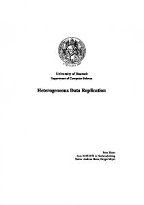
2. Rationale To illustrate the benefit and rationale behind FPFR, consider the example shown in Figure 1. Part (1) of the figure shows four cluster nodes and the network topology with bi-directional links. The goal is to replicate a file from node A to rest of the nodes (B, C and D) in minimum time; the size of the file is 1GB.
B
B
10MB/s
A
10MB/s
C
10MB/s
10MB/s D
(1)
A
C
10MB/s
D
(2)
Replicate 1GB file from A to (B, C, D)
Finishing time = 200 sec
B
B
A
A
C
C
D
D
(4)
(3) Finishing time = 100 sec
Finishing time = 50 sec
Figure 1: Rationale of FPFR.
Part (2) illustrates the first strategy that can be applied directly using existing point-to-point data transport tool such as GridFTP. In this case three transfer sessions are created from A to all destination nodes with the link AàB shared by two sessions. Each of the sessions (AàB and AàC) gets 10MB/s peak capacity in the link AàB. Therefore, the maximum finishing time of the replication process is 200 sec. Part (3) shows an improvement by creating a single tree from A connecting B, C and D. In this case, multiple sessions through same link are avoided: the session from AàB replicates data on B and from B the data is relayed through a separate session to C. In order to have concurrent sessions along AàB and BàC, one needs to split the file into small sub-files and create sessions for each sub-file in a pipelined manner. Each of the sessions can thus utilize peak capacity 100MB/s resulting in finishing time of 100 sec, which corresponds to acceleration of distribution by a factor of two. Part (4) provides further improvement by utilizing the spatial diversity of the network topology if nstead of just having one tree, if we use two trees (Figure 1). The first tree is (AàBà(C, D)) and the second tree is (AàDà(B, C)). Since each session can achieve the peak capacity, the total finishing time of 50 sec, which corresponds to the acceleration of distribution by a factor of four. Evidently, the acceleration of distribution (speedup) in a small topology of 4 nodes shows the potential of the strategy. The FPFR tool that we describe is based on the parallel replication strategy; it can work over local and wide area networks including the Internet. The remaining part of the paper provides details about FPFR tool related to its functionality, implementation and performance.
3. How does it work? 3.1. Point-to-multipoint transfer At the source node, the original file F is split into small and equal sized sub-files: S 1 , S 2 , …, S n . The size of the sub-files is pre-determined. A given sub-file S is transferred using a reliable point-to-point transport protocol (such as GridFTP) to a chosen next hop node X as determined by the forwarding tree configuration (Figure 2). As shown in Figure 2, node X acts as relay: it opens two new concurrent point-to-point sessions connecting to nodes A and B and then transfers S. The relay part functionality is similar to the Diskrouter [10]. Finally, the sub-file S is transferred to each destination node using the forwarding tree configuration. The original file F is subsequently reconstructed at each destination after receiving all the sub-files. Assembly from sub -files S1 S2
A
F Sn Disassembly into sub-files
WAN/Internet
S
Replicate/relay each sub-file from disk (eg. Diskrouter )
B X Reliable point-to-point data transfer (GridFTP)
Figure 2: File distribution mechanism in FPFR.
3.2. Creation of replication trees The performance of FPFR in terms of effective speedup of replication depends on the topology of the forwarding trees. We outline several approaches of creating the trees; their performance is analyzed in the next section. Hierarchical approach (H): In this approach, the trees are constructed by placing the nodes in a hierarchical fashion, and nodes in upper level are used to forward sub-files to nodes in lower level. An example of this approach, FastReplica is presented in [11]. In FastReplica, for N destination nodes, the source opens N concurrent connections, one for each destination node. Each of the N destination nodes then relays the sub-files it receives to the complementary N-1 nodes using N-1 concurrent connections. This construction thus forms two levels of hierarchy; it is unaware of the link and server capacity and independent of the underlying network topology. Iterative DFS approach (I-DFS): In this approach, the first tree is a result of a depth-first search (DFS) that provides a tree with source as the root and spans all the destination nodes. For the resulting tree Ti , the bottleneck bandwidth Bi is obtained (minimum bandwidth over all the links in the tree). The bottleneck bandwidth Bi is then subtracted from the bandwidths of the links in Ti and DFS is repeated to create the second tree. The process is repeated unless no more valid tree (spanning all the destination) can be created. The advantage of the DFS strategy is that the number of concurrent sessions from a given node remains small. Iterative BFS approach (I-BFS): This approach is the same as I-DFS except the breadth-first search (BFS) is used to construct the trees.
Iterative shortest-widest approach (I-SW): In this approach, the first tree is created based on finding the widest shortest path tree using Dijkstra algorithm with bandwidth metric used on edges. Once the first tree is created, the remaining trees are created in the same iterative manner as in I-DFS and I-BFS approaches. Figure 3 illustrate the trees constructed based on the above methods for the example shown in Figure 1. We note the following important points: the number of trees (3) created by Hierarchical approach creates the largest number (three) of trees with the worst performance (finishing time). Thus, having more trees does not necessarily increase the replication speed-up. Also, in this example, both I-BFS and I-SW strategies result in the same tree configuration. The I-DFS based approach results in the highest replication speed-up. In the last three of the described approaches, the network topology and available bandwidth of the links available bandwidth have to be known a priori (Hierarchical does not utilize bandwidth information). Such information can be acquired in Data Grid architecture from the Network Weather Service [8]. B
B
A
C
B
A
C
D
A
C
D
D
Iterative BFS and Shortest-Widest: finishing time 10 secs
Iterative DFS : finishing time 5 secs
D
A
A
A
B
C
D
C
D
B
B
C
Hierarchical approach : finishing time 20 secs
Figure 3: Example of replication trees.
3.3. Tree maintenance In realistic networks, the link bandwidth does not remain stationary over time. In a shared environment like Internet, each traffic flow shares its links with other applications. Therefore, different trees will provide different data transfer speed, depending on their topology. The traffic through each tree can be balanced using the following approach. The control in sub-file dispatch for load balancing follows similar approach used in TCP. After receiving the complete sub-file S i , a given leaf node in a tree sends an acknowledgement (ACK) back to its parent with the subfile number i. Each relay node, after receiving ACKs for sub-file S i from all its children sends an ACK to its parent. Finally, when the ACK propagates to source, it implies that sub-file S i is replicated to all the nodes. For each tree, the replication session manager maintains a threshold on the number of un-acknowledged subfiles that have been already dispatched from the source. If that threshold is crossed, any file transfer for that tree is halted until an ACK for that tree is received. If the bandwidth in one or more links in a given tree goes down, the sending rate on that tree will be accordingly reduced. If load control is not used, the file dispatch will be done at the transfer rate achieved by the concurrent point-to-point transfer sessions originating at the source node. The concern for reliability only arises if a node failure leads to breaking of one or more trees. Simple packet level and network level reliability is managed the point-to-point transport protocol along with RFT [9] (as proposed in Data Grid). If a node fails, the trees have to be reconstructed. However, all lost sub-files (stationed at the failed node) have to be delivered to the destination node. To do that, the session manager creates a temporary point-to-point session directly connecting each destination node and sends all the un-acknowledged sub-files and subsequently reverts to the tree-based transfer.
3.4. System implementation The system prototype is divided into control plane and data plane. The control plane is in charge of session state management, and distributed tree state managements in data transfer sessions. The data plane takes care of data replication and forwarding, congestion control on a tree and load balancing between trees. Session state is a 5-tuple of {session_id, source, destination lists, source file name list, source-to-destination file name map}. It reflects the single -source-multiple-destinations parallel replication nature of our system. In our data transfer session model, the destination list is fixed during the life of a session. This model is different from multicast-based streaming and peer-to-peer file download model, where the destinations can join and leave in a single data session. We choose this model because there are varieties of such applications in file replication of storage system, content distribution network and data replication in grid environments, where the destinations are chosen in advance manually or automatically by out-of-band algorithm and the destination list are fixed in a data transfer session. The source file name is the file name in the data source and the source-to-destination file name map translates original file name to destination file names. Such file name presents the file physical location, consists of node name, directory name and file name, and is encoded as URI. This map allows the file created in each destination to be different from the original in name and directory. This is a very important feature when file systems structure on different sites are different from each other. It shares the same vision as the logic file name to physical file name map in replica catalog service. Our system can integrate with such replica catalog service with trivial translation. (Note: replica catalog service maintains a map from logic file name to target file names, while in our replication session, the session maintain a map from file name at source to file names at multiple destinations). In each data transfer session, all files share same destination node list, and all files are transferred in a batch. In each session, the trees (based on the algorithms described in 3.2) are created to span all the destinations. The control plane distributes the tree soft state to all forwarding nodes using explicit signaling, and the state is refreshed periodically. The currently implemented signaling is similar to explicit source multicast in that the tree structure is encoded in a message and the message propagation follows the encoded tree structure. The soft state and periodical state refresh simplified the system implementation and improved its robustness. Session manager/controller currently assumes the central role of control plane in our implementation. It accepts data feeds from monitoring system, maintains session state and orchestrates tree state signaling on each forwarding node. The session manager is an independent component; it interacts with session agent in each node through distributed messaging. Our implementation of session manager supports both centralized and distributed session managements. In centralized mode, a single session controller orchestrates all sessions from different sources. In distributed session management, a session manager associates/collocates with each node and only manages session originating from the source node, which distributes session management load uniformly on each data-source node. Our distributed session management scheme scales independent of network sizes. The data plane consists of data forwarding and replication, congestion control and load balancing between trees. The data plane on each node maintains a forwarding table mapping a forwarding tree to the next hops. This forwarding table is signaled by session management process in control plane. Data frame is tagged with {source_id, session_id, tree_id, file_id and subfile_id}; the {source_id, session_id, tree_id} tuple is used as index to query forwarding table in order to find forwarding destinations. We also implemented congestion control and load balancing as briefly described in section 3.3. To avoid overflow in a tree node due to variations of network bandwidth, the congestion control described in section 3.3 limits the tree forwarding speed to the bandwidth of slowest tree link. In order to take advantage of forwarding capacity on all trees, while sending each sub-file to a tree at source, we always choose the tree with the largest available forwarding buffer. The data plane of each node consists of three components: sender, forwarder and receiver. Forwarder is a multicast component that can duplicate incoming data and forward it to multiple outgoing connections according to the installed multicast routing table. A forwarder can be activated on non-destination nodes. Sender is activated on the file source. It fragments data files in to sub-files, sends sub-files to multiple trees and performs load balancing between trees. Receiver is activated on each destination. It receives sub-file and reconstructs the
original file according to the meta-data in the header of each received sub-file and session information such as file name and file name map.
4. Performance of FPFR The performance of FPFR tool was evaluated using both simulations and actual deployment in a local network and over Internet. More detailed results along with the FPFR tool itself will be posted soon at http://gridnet.nec-labs.com. 4.1. Simulations The performance of FPRF depends upon the algorithm used to create the trees. We evaluated all four types of trees creations algorithms: Hierarchical (H), Iterative DFS (I-DFS), Iterative BFS (I-BFS) and Iterative shortestwidest (I-SW). The speedup of algorithm R is defined as the ratio of the finishing time using direct P-2-P (pointto-point sessions between the source and every destination node) to the finishing time of R (time to replicate the data to all nodes).
H
I-DFS
I-SW
I-BFS
30 25
speedup
20 15 10 5 0 8
12
16
20
32
number of nodes in network
Figure 4: Dependence of speedup on the number of nodes.
Figure 4 shows the simulation results, where each point is an average over 100 different randomly generated networks (using Waxman’s model [12]) containing the same number of nodes. The x-axis shows the number of nodes and y-axis shows the speedup. The simulations show that I-DFS consistently delivers the maximum speedup for networks with various numbers of nodes. 4.2. Testing in a local network The FPFR tool was implemented and tested in test-bed is comprised of four nodes A, B, C, D, with one sender at A and three receivers at nodes B, C and D (as shown in Figure 1). The available bi-directional link bandwidth was set up to 10Mbps. The forwarder component of the system was installed at all four nodes. We use the total replication time of the bulk file data as the performance metric. The timeline was defined in the sender’s clock and the data replication finishing time is defined as the time when the sender A receives ACKs of data completion from all the receivers B, C and D. The inaccuracy of the replication time is negligible since the transferring time is
several orders of magnitude higher than the signaling overhead. For comparison, we implemented two other file transfer schedules on our testbed: multicast and direct P-2-P. We changed the size of the distributed file during multiple runs on the testbed; the recorded results are shown in Figure 5. As expected, in the considered network topology, FPFR (using I-DFS) distributes files on average two times faster than the multicast algorithm, and four times faster than P-2-P.
FPFR using I-DFS
multicast
Direct P-2-P
140
finishing time (sec)
120 100 80 60 40 20 0 10
20
40
80
file size (Mb)
Figure 5: Finishing time in a local network.
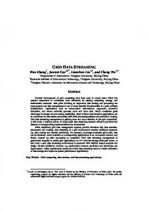
4.3. Testing in a global network The FPFR tool was implemented and tested in PlanetLab [13] consisting of several PCs (up to 50 and more) deployed across US and Europe, which are connected through Internet.
(a)
(b) Figure 6: FPFR implementation on PlanetLab.
We implemented FPFR with a simple graphical interface, connected to session manager to perform interactive session management and to demonstrate the functionality of the tool, as shown in Figure 6. In part (a) of Figure 6, the left window shows the sessions and session related data, such as session status (created, invited, finished), session progress, session time, total data transferred, and etc. The upper right window shows the destination lists in each session. The lower right window shows the files related to a session; it also allows user to add a file and remove a file before activate a session. In part (b) of Figure 6, the right window of the figure shows the network for a replication session from a source in Los Angeles to 10 destinations around US. Multiple trees are created between source and destinations as shown in the lower part of left windows. The session achievable capacities of each of the proposed algorithms based on monitored data are evaluated and shown in the bar graph. In this setting, the I-DFS outperforms others. Experiments were conducted to compare the finishing time of I-DFS with Direct P-2-P as shown in Figure 7. The figure shows different number of PCs used in the experiment. Over a wide range of nodes, I-DFS provides the speedup of up to 9 (reached for large number of nodes). Increase of the number of nodes magnifies the level of speedup since it increases network diversity, which is essential for the strategy of using multiple trees. Figure 8 shows the variation of net bandwidth from using I-DFS and Direct P-2-P with time for a particular destination node showing that over a long time range bandwidth from I-DFS remains consistently higher than that of the Direct P-2-P. Direct P-to-P
FPFR using I-DFS
90
Replication Finishing Time (Second)
80
70
60
50
40
30
20
10
0 1
2
3
4
5
6
7
8
9
10
11
12
# of nodes in the network
Figure 7: Finishing time in a global network (PlanetLab).
5. Conclusions This paper presents and discusses a fast parallel file replication (FPFR) tool. This tool by creating multiple distribution trees through pipelining point-to-point transfer sessions (e.g., GridFTP) minimizes the net file replication time. Performance evaluation in Internet environment indicates a speed up factor of up to 9 times by using the FPFR tool based on I-DFS tree construction.
Direct P-to-P
FPFR using I-DFS
10
9
bandwidth (Mb/s)
8
7
6
5
4
3
2
1
0 1
2
3
4
5
6
7
8
9
10
Time (X10 second)
Figure 8: Variation of net bandwidth during replication.
6. References [1] A.Chervenak, I.Foster, C.Kesselman, C.Salisbury, and S.Tuecke, The Data Grid: Towards an Architecture for the Distributed Management and Analysis of Large Scientific Data Sets. J. Network and Computer Applications, 2001. [2] EU Data Grid Project, “The Data Grid Architecture”, DataGrid-12-D12.4-333671-3-0, 2001. [3] Grid Datafarm, http://datafarm.apgrid.org/. [4] I. Foster and C. Kesselman, "A Data Grid Reference Architecture," GriPhyN 2001-6, 2001. [5] Sabul, www.dataspaceweb.net/sabul.htm [6] FAST TCP, http://netlab.caltech.edu/FAST/ [7] Reliable Blast UDP: Predictable High Performance Bulk Data Transfer, IEEE Cluster Computing, 2002. [8] Network weather service (NWS), nws.cs.ucsb.edu/ [9] Reliable File Transfer, www-unix.globus.org/toolkit/reliable_transfer.html [10] Diskrouter, www.cs.wisc.edu/condor/diskrouter/ [11] L.Cherkasova and J.Lee, FastReplica: Efficient Large File Distribution Within Content Delivery Networks, USITS 2003. [12] W B. M. Waxman, “Routing of multipoint connections,” IEEE Journal of Selected Areas in Communications, pp. 1617–1622, 1988. [13] PlanetLab, www.planet-lab.org