FAST-Robots: a rapid-prototyping framework for intelligent mobile robotics Holger Kenn, Stefano Carpin, Max Pfingsthorn, Benjamin Liebald, Ioan Hepes, Catalin Ciocov and Andreas Birk School of Engineering and Science International University Bremen P.O. Box 750561, Bremen, Germany email:
[email protected] ABSTRACT FAST-Robots (Framework Architecture for Selfcontroled and Teleoperated Robots) is an object-oriented network control architecture framework for robotics experiments that supports mixed teleoperation and autonomy. Its features are the abstraction from the underlying communication system and its simplicity and flexibility towards modification and extension. This architecture is used aboard mobile robots in the Robocup Rescue Robots League. KEY WORDS Robotics, Control Architecture, Teleoperation, Autonomous Systems, Robocup Rescue Robots League
1 Introduction In the recent years, applications of artificial intelligence systems in mobile robots have gained popularity among both the general public and researchers. Robotic systems such as the Sojourner Rover of the 1997 NASA Pathfinder Mission[1, 2] or the robots of the Robocup Robotic soccer competitions[3] have gained public attention but similar robotic systems are used today in various fields, e.g. in underwater robotics[4]. Most systems integrate on-board control based on AI techniques with teleoperation capabilities using off-the-shelve network components. For various experimental sciences, the use of AI, robotics and computer networks for remote operation of experiments is becoming more and more important. The examples reach from simple webcam systems for visual inspection to complete fiber optic computer networks to be deployed on the ocean floor as in the NEPTUNE project[5]. For remote operation of mobile robots, there are several commercial software packages available, but these often only support the vendor-supplied robots, sensors and actuators. A simple, vendor-independent software architecture for mobile robotics would not only ease the application of autonomous and tele-operated robotics for other experimental sciences, it would also allow the reuse of sensor systems and application software developed by other scientists and ease the repetition of experiments. For general robotics applications, other scientific
projects have started to design and implement such software architectures, one example is the OROCOS project[6]. Unfortunately, the OROCOS approach resulted in a highly complex system that tries to cover almost all robotic systems and applications but currently focuses mainly on industrial robot arms. For the robots of the IUB Robocup Rescue Team 2003, the available architectures were found unsuited. Therefore, a simplified network control architecture has been developed that fulfills current and future requirements for mobile robotics research and is still easy to use by nonexperts. It is provided as sourcecode under a GNU Public License. The remainder of the paper is structured as follows: First, the general requirements for a network control architecture are presented, then, the robots of the IUB Robocup Rescue Team are presented as a general example for a flexible robotic system. The structure of the FAST-Robots network control framework is then explained and an example for the extension of the framework with a new sensor is given.
2 Requirements for the software architecture In order to provide an useful tool for the implementation of tele-operated experimental platforms, several issues have to be addressed in the design of the software architecture: Combination of teleoperation and on-board control: Most mobile robotic systems, especially the more complex ones include both autonomous functions and teleoperation, even if the teleoperation aspect is only used for test and data analysis purposes. Support for these two modes of operation (or even a combination of both) is a necessity. Simplicity: Robotic platforms used in research are often used for different experiments and the focus of the researchers is not on software engineering. Therefore, the architecture has to provide a number of building blocks that can be used in a straight-forward way.
Flexibility: Although there are some common aspects of all mobile robots such as motion and localization, there are often some specific functions for different experimental setups and often, special software has to be integrated for these functions. The architecture has to support this integration with the least possible effort. Reusability: In order to avoid unproductive reimplementation of existing functionality, the software architecture has to support code reuse, not only in the way that many components are available ready to be used but also that it is simple to author new components and contribute to the overall development. Robustness: Due to the nature of the communication systems used aboard mobile robots, i.e. wireless networks, it cannot be avoided that the communication system occasionally fails. The architecture not only has to be able to recover from such failure but has to ensure safe operation of the mobile robot during failure. Recovery from failure may include more than just waiting for the communication system to recover, i.e. the mobile robot may try to locate a better position or several redundant communication systems may be used in a failover setup. The latter may be available through existing communication infrastructures but the former needs active support from the software architecture, i.e. the detection of a failure condition and the signaling of the condition to the appropriate components that initiate the recovery.
3 The Rescue Robots The engineering aspects of an application-oriented project like rescue robots are of tremendous importance. The robots have to have a significant amount of robustness, suited locomotion capabilities that go beyond what is needed in normal office environments, and nevertheless sufficient flexibility to allow for an exploration of the unsolved scientific questions linked to this field. Based on the experiences with prototype robots [7, 8] that participated in the RoboCup Rescue competition 2002 in Fukuoka, Japan, two new types of robots were developed that are shortly presented here. The robots are based on complete in-house designs, ranging from the mechanics over sensors and actuators to the software level. This allows to optimize the designs for the particular tasks of rescue operations. The implementation of the robots is based on the so-called CubeSystem [9, 10]. The CubeSystem is a collection of hardware and software components that allow the rapid prototyping of robots. The central component is the so-called RoboCube [11], a very compact but yet powerful embedded controller.
Efficiency: As mobile robots are often operating under severe energy constraints, their available CPU power is limited. Moreover, the bandwidth on the available communication links may be limited too and several on-board systems may compete for it. The software architecture therefore has to be very efficient and must limit its ressource usage both in compute performance and in induced communication overhead. Realtime Aspects: Teleoperation of a mobile robot obviously has some realtime aspects. Apart from the fact that the robot should have some on-board safety measures that maintain a safe state upon communication failure, the software architecture has to provide some means for maintaining low-latency communication for some designated part of the network communication, e.g. for the motion control commands issued by the operator or for sensory data that is used by to operator to issue those motion commands. Other communication data may either be queued for transmission or discarded. The software architecture has to provide means to schedule the network communication under various conditions, (e.g. loss of available bandwidth) so that low-latency operation is maintained.
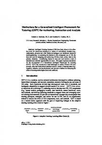
Figure 1. The 6-wheeled rescue robot.
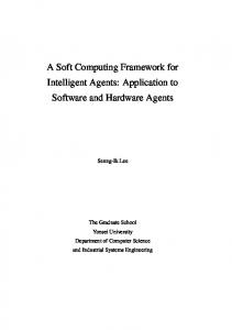
The two main new types of rescue robots are the socalled papa- and mother-goose robots. These nicknames are derived from the fact that they can cooperate with a set of small autonomous robots called the ducklings. Papagoose is based on a differential six-wheel drive (figure 1). It is rather large with a footprint of 450mm × 400mm to allow for a standard ATX-size PC motherboard (figure 2) in addition to its CubeSystem components and a significant
payload. Its on-board batteries allow for roughly 1 hour of intensive use in difficult terrain and up to 10 hours of operation with sparse locomotion. Mother-goose is with a footprint of 400mm × 300mcm much slimmer. Due to its tracked drive (figure 3), it is capable to negotiate stairs. To save weight and space at the expense of cost, mothergoose is equipped with an embedded PC in addition to a CubeSystem. Both robots are designed to carry a rich set of sensors, such as • Frontal Laserscanners (Hokuyo Automatic) that cover 162 degrees in 91 steps up to 4m depth . • high-resolution Cameras (Philips) • Inertial Navigation Sensor System based on rate gyroscopes and acceleration sensors.
Figure 2. The interior of the 6-wheeled robot. It hosts a full fledged PC.
• Robocup-rescue specific sensors such as CO2 and passive infrared body-heat for victim recognition and hazard sensors such as optical smoke detectors. • high precision intelligent Ultrasound Sensors (Baumer Electric) for medium range (up to 7 m) • active InfraRed Sensors (Sharp) for short range (up to 70 cm) sensing • redundant flux-gate based digital compass devices (Philips and Honeywell) with up to 0.5 degree resolution In addition to these payload sensors, the motor-units of the robots are equipped with high resolution 500 ppr quadrature encoders. The software side of the CubeSystem uses these sensors not only for motor- and motioncontrol, but it also provides library functions for odometry and dead-reckoning that are available as additional sensor devices. Moreover, the robots are equipped with electromechanical bumpers consisting of special profile rubber tubes with shock-absorption capabilities and an internal highly sensitive switch matrix.
4 Structure of the software architecture
Figure 3. The basic mechanics of the tracked rescue robot. It is designed to climb stairs.
FAST-Robots has been implemented in the form of an C++based object-oriented framework, i.e. the user implements additional functionality by deriving from base classes provided by the framework and registering instances of these objects with the framework and then passing control to the framework. As the framework provides a number of generic classes, a simple system can be constructed by only instantiating and registering the classes provided. The two main entities of the system are the command station and the experiment platform. The command station is the application program run by the operator. It provides a graphical interface to the sensory data of the experiment platform and controls the actuators of the robot. The experiment platform is the program running on the on-board computer
of the robot. It can be contacted by the command station and then provides an interface to the on-board sensors and actuators of the robot. The software on the robot is structured into experiments. Every experiment object has a number of sensors and actuators and can be contacted by a monitor object running on the command station. This allows that different experiments on the same robot are controlled by different command stations. The experiment also includes local control, i.e. a direct coupling of sensors and actuators to a local program implementing feedback. For a mobile robots, the sensors used for local control would be grouped into a single experiment that could then implement motion control and path planning. On the command station, the software is structured into so-called monitors. Each monitor has several displays that display sensor data and controls that represent the actuators. Each monitor can be associated with an experiment on a robot, with the possibility of instantiating a monitor several times in order to connect to several similar experiments on different robots. Robot
Operator Station
Platform
Command
1
1
1..n
1..n
Experiment 1
0..n
Sensor
Monitor
1
1
0..n
Actuator
1
0..n
0..n
Display
Control
Figure 4. FAST-Robots class diagram
With this structure, it is possible to adopt the FASTRobots architecture to various applications.
5 Network Communication The network communication itself is established and maintained between the experiment and the monitor in which the monitor is initiating the connection that the experiment expects. By this, an experiment can be run unconnected and a monitor can reconnect to it at a later time. Each sensor, actuator, control and display is represented in the system through an object with the respective virtual base class. The instantiation, destruction and handling of these objects is done in the user-supplied main application. The communication between a specific sensor object and its display object (or between a control object and its actuator object) is abstracted by the experiment and moni-
tor objects. The applications register these objects with the framework and then pass control to the framework. Every pair of sensor and display objects are associated with a matching object of base class NetworkData , e.g. a pair CTemperatureSensor and CTemperatureDisplay is associated with a CTemperatureNData. The NetworkData objects implement methods to convert sensor data objects into a memory buffer and vice versa. Sensor
Display NetworkData
TemperatureSensor
TemperatureDisplay TemperatureNData
Figure 5. Associations between the sensor, network and display classes The sensor objects implement a simple query-based interface. Upon the call to the interface, they return an object with the base class NetworkData that is then transmitted to the command application where it is casted into the appropriate object type derived from NetworkData and passed on to the appropriate display object to be displayed. This approach has the advantage that it is very easy to extend the system with additional sensor and display objects. Moreover, it is quite flexible as the sensor objects can be very well tailored to the type of data provided by the sensor, e.g. to provide data compression or to implement an asynchronous interface to synchronous sensor systems by implementing a sensor thread. Independent of the underlying network, the experiment level maintains data integrity of the NetworkData objects, i.e. it makes sure that the objects arrive intact, but not necessarily all or in any particular sequence. The advantage of this restriction is that network protocols can be used that do not provide ARQ schemes or sequence maintenance and can therefore provide lower latency, i.e. if a packet arrives, it mostly arrives with a low latency. However, sensor or actuator data that relies on a well-defined end-to-end latency should include additional timestamps in their Network Data subclass and use buffer sizes below the path MTU of the underlying network in order to prevent additional latency through fragmentation/reassembly. The architecture contains a class that contains all network-specific code. The class provided with the framework is a TCP/IP based implementation, but it can be replaced with a different class using a different network infrastructure provided that it is able to transmit blocks of binary data. The scheduling of network resources is a critical part of the architecture. For this, there are several approaches possible.
The simplest way is to implement a priorityless round-robin schedule. In this, every data source (sensor or control) is queried regularly for available data and this is sent directly. This approach is useful if the bandwidth available cannot be filled by the available data sources, like it is often the case in wire-based local area network systems. However, it does not guarantee any communication properties. A seemingly better approach is a prioritized schedule that first checks all sensors for available data and sends the data with highest priority. Although this approach guarantees the maximum bandwidth for the sensor with the highest priority, no other guarantee can be given. Additionally, it can be seen from this example that only providing priorities without taking other information about the sensors into account cannot even guarantee the low-latency operation of a single sensor as it might be sending more than the available network data rate and thus, this may lead to data loss or queuing. A better scheduling approach would have to take more information into account such as the amount of data provided by the data sources, the interval at which the data is provided, the currently available network bandwidth and the properties of the underlying network architecture. As shown here the network communication scheduling has to be decided upon the properties of the experiment and the network communication system used, the architecture therefore allows the exchange of the network communication scheduler through its object-orientation. This flexibility is especially important as negligence in this may lead to unexpected results. For example, the IEEE802.11 wireless network uses a layer-two based ARQ scheme that cannot be disabled, this leads to the occasional reception of old packages after a communication failure even if a ARQ-less protocol like UDP is used., i.e. the first packet that could not be transmitted is stored in the bridge buffer of the wireless access point or the wireless LAN adapter driver until the communication reestablished, however, all subsequent packets are lost. Only after that old packet has been delivered, newer packets can reach their destination. A possible approach to overcome these limitations is the modification of the low-level protocol implementation or the implementation of a network communication scheduler that is aware of the limitation of the lowlevel network communication system and treats data objects transmitted through these networks accordingly.
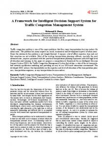
small and cheap, it is an ideal device for being mounted on the mobile platforms we are currently using in the robotic rescue context. Communication with the sensor is done via a proprietary protocol over a serial line. In order to integrate it in the Platform/Command structure it is necessary to derive a class from Sensor and a class from Display. The class inherited from Sensor, called PB911Sensor, handles the communication via the serial port with the hardware. That is, it initializes the device, it queries for readings if necessary, and it decodes data. Moreover, the code includes consistency checks, and it is able to detect erroneous working conditions and to reinitialize the device itself. Thus, from the client code point of view, it provides a reliable stream of distance readings. On the operator station side, a class PB911Display is created by inheriting from Display. This class acquires the readings produced by the sensor and displays them in a GUI widget. Figure 6 illustrates how the rendering of the PB911 data is performed inside the monitor. The bridge between the two is the class PB911NData, which inherits from NetworkData. The PB991NData provides just two methods in order to serialize or deserialize the sensors’ pertinent data to/from a buffer. In the case under analysis, the two methods just write or read the sequence of 91 distance measures. The consistent transmission of the buffer over the network is handled at the base class level, thus nothing else is needed in order start operating with the sensor. It can be appreciated that developing the code for handling a new sensor or actuator is extremely easy and fast, as it is possible to concentrate just about the hardware and the display details, while relying on the lower levels components for communication related issues.
6 The PB9-11 interface As an example of the application of the FAST-Robots software architecture, in this section we describe the implementation of the software handling the PB9-11 sensors equipping the robotic platforms we are actually using. The PB9-11 is a photoelectric sensor for obstacle detection based on the time of flight principle. The sensor scans a symmetric area 162 degrees wide subdivided in 91 sectors and can measure distances up to 4 meters. Being light,
Figure 6. A screenshot of an experiment using the PB911 sensor display object
7 Conclusion The advantage of the FAST-Robots architecture over existing other approaches are its simplicity, its flexibility, its efficiency and the availability of the source code. Therefore, it can be used for various applications of which one, Robocup Rescue, is presented in this paper. Obviously, there are numerous points in which FASTRobots could be extended, e.g. towards multi-robot systems and cooperation. But we see this as a starting point only with the main focus on simplicity and ease of use. Other points such as general problems of low-latency realtime network communication over unreliable network links are current topics of research and results can be included in subsequent releases of the software. Applications of the FAST-Robots currently are focussed on the mobile robots of the IUB RoboCup rescue team, but in the future, applications for autonomous submersibles are envisioned. We wish to encourage other researchers to use our architecture for their applications, hopefully leading to mutual code reuse and by this, our architecture could become part of a robust software infrastructure for research on tele-operation and autonomy.
[6]
Herman Bruyninckx Open RObot COntrol http://www.orocos.org/
[7]
Andreas Birk and Holger Kenn. A control architecture for a rescue robot ensuring safe semi-autonomous operation. In Gal Kaminka, Pedro U. Lima, and Raul Rojas, editors, RoboCup-02: Robot Soccer World Cup VI, LNAI. Springer, 2002.
[8]
Andreas Birk, Holger Kenn, Martijn Rooker, Agrawal Akhil, Balan Horia Vlad, Burger Nina, Burger-Scheidlin Christoph, Devanathan Vinod, Erhan Dumitru, Hepes Ioan, Jain Aakash, Jain Premvir, Liebald Benjamin, Luksys Gediminas, Marisano James, Pfeil Andreas, Pfingsthorn Max, Sojakova Kristina, Suwanketnikom Jormquan, and Wucherpfennig Julian. The iub 2002 rescue robot team. In Gal Kaminka, Pedro U. Lima, and Raul Rojas, editors, RoboCup-02: Robot Soccer World Cup VI, LNAI. Springer, 2002.
[9]
Andreas Birk, Holger Kenn and Luc Steels. Programming with behavior processes. International Journal of Robotics and Autonomous Systems, 39:115–127, 2002.
[10]
Andreas Birk, Holger Kenn, and Thomas Walle. On-board control in the robocup small robots league. Advanced Robotics Journal, 14(1):27 – 36, 2000.
[11]
Andreas Birk, Holger Kenn, and Thomas Walle. Robocube: an “universal” “specialpurpose” hardware for the robocup small robots league. In 4th International Symposium on Distributed Autonomous Robotic Systems. Springer, 1998.
References [1]
Matijevic, J. Mars Pathfinder Microrover Implementing a Low Cost Planetary Mission Experiment Proceedings of the Second IAA International Conference on Low-Cost Planetary Missions, John Hopkins University Applied Physics Laboratory, Laurel, Maryland, April 1996.
[2]
Morrison, J. and Nguyen, T. On-Board Software for the Mars Pathfinder Microrover, Proceedings of the Second IAA International Conference on Low-Cost Planetary Missions, John Hopkins University Applied Physics Laboratory, Laurel, Maryland, April 1996.
[3]
Hiroaki Kitano and Minoru Asada and Yasuo Kuniyoshi and Itsuki Noda and Eiichi Osawa RoboCup: The Robot World Cup Initiative, Proc. of The First International Conference on Autonomous Agents (Agents-97), ACM Press, 1997
[4]
Davd Wettergreen, Chris Gaskett, and Alex Zelinsky Autonomous Control and Guidance for an Underwater Robotic Vehicle Proceedings of the International Conference on Field and Service Robotics (FSR’99), Pittsburgh, USA, 1999
[5]
The NEPTUNE project http://www.neptune.washington.edu/
OROCOS: Software