best of our knowledge, this is the first time that three-dimensional, agile maneuvers .... 30 s on a simple laptop (at least 5 times faster than state of the art) and ...
Fast Trajectory Optimization for Agile Quadrotor Maneuvers with a Cable-Suspended Payload Philipp Foehn1 , Davide Falanga1 , Naveen Kuppuswamy2 , Russ Tedrake2 , Davide Scaramuzza1
Abstract—Executing agile quadrotor maneuvers with cablesuspended payloads is a challenging problem and complications induced by the dynamics typically require trajectory optimization. State-of-the-art approaches often need significant computation time and complex parameter tuning. We present a novel dynamical model and a fast trajectory optimization algorithm for quadrotors with a cable-suspended payload. Our first contribution is a new formulation of the suspended payload behavior, modeled as a link attached to the quadrotor with a combination of two revolute joints and a prismatic joint, all being passive. Differently from state of the art, we do not require the use of hybrid modes depending on the cable tension. Our second contribution is a fast trajectory optimization technique for the aforementioned system. Our model enables us to pose the trajectory optimization problem as a Mathematical Program with Complementarity Constraints (MPCC). Desired behaviors of the system (e.g., obstacle avoidance) can easily be formulated within this framework. We show that our approach outperforms the state of the art in terms of computation speed and guarantees feasibility of the trajectory with respect to both the system dynamics and control input saturation, while utilizing far fewer tuning parameters. We experimentally validate our approach on a real quadrotor showing that our method generalizes to a variety of tasks, such as flying through desired waypoints while avoiding obstacles, or throwing the payload toward a desired target. To the best of our knowledge, this is the first time that three-dimensional, agile maneuvers exploiting the system dynamics have been achieved on quadrotors with a cable-suspended payload.
S UPPLEMENTARY MATERIAL This paper is accompanied by a video showcasing the experiments: https://youtu.be/s9zb5MRXiHA I. I NTRODUCTION A. Motivation Aerial manipulation with Micro Aerial Vehicles (MAVs) is a compelling application domain with applicability within a wide variety of dangerous situations, such as disaster scenarios. Potential applications are post-disaster response, to quickly provide victims with life-saving aid, and fire fighting, in the case that flames cannot be easily and safely reached by human operators or ground-based fire-fighting systems. In each of these scenarios, time is a critical factor and the vehicles have to be capable of executing agile maneuvers at high speed to render aerial manipulation effective. This research was funded by the DARPA FLA Program, the National Center of Competence in Research (NCCR) Robotics through the Swiss National Science Foundation and the SNSF-ERC Starting Grant. 1 P. Foehn, D. Falanga, D. Scaramuzza are with the University of Zurich, Switzerland rpg.ifi.uzh.ch . 2 N. Kuppuswamy, R. Tedrake are with the Toyota Research Institute, Cambridge, USA www.tri.global , and R. Tedrake is also with the Massachusetts Institute of Technology, USA www.csail.mit.edu .
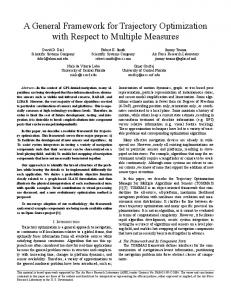
Fig. 1. Our quadrotor flying a trajectory through multiple waypoints while carrying a cable-suspended payload.
Partially or fully actuated manipulators have been used for aerial manipulation by attaching them to quadrotors [10, 11, 22, 27]. Although this solution is suitable for fine manipulation and interaction with the environment, it has a number of drawbacks (e.g., energy consumption, size of the overall platform, additional inertia) that reduce the agility of the vehicle. Conversely, object manipulation through cable suspension significantly reduces the mechanical complexity and the weight of the system, and requires minimal energy since no additional actuation is needed. In contrast to the actuated manipulator approach, cable suspension systems introduce a variety of challenges in modeling the system dynamics and parameterizing specific behaviors to accomplish a desired task. Variations in the cable tension dramatically change the description of the dynamics, since the payload can either transfer forces through the cable to the vehicle or not, depending on whether the rope is taut or not. A hybrid dynamic model is usually introduced to deal with the varying structure of the system, with different mathematical descriptions (also called modes) depending on the cable tension. This provides an accurate description of the system but renders the trajectory optimization difficult to solve. Indeed, hybrid optimization is computationally expensive and requires a-priori specification of the desired mode sequence through the trajectory. Furthermore, this formulation often leads to difficulties in specifying convex constraints for safetycritical features, such as cable-snagging and requires complex task-specific parameter tuning. Additionally, taking workspace considerations, such as obstacles into account within the set of constraints is difficult and leads to additional challenges for the trajectory optimization. B. Related Work The state of the art in cable-suspended aerial manipulation can be broadly classified into two approaches: (i) feedback control for tracking desired payload trajectories [7, 8, 18];
(ii) trajectory planning for a quadrotor with slung-load system [25, 24, 3, 5, 16, 17, 28]. In this work, we focus on the second approach. A possible solution is to minimize the swinging behavior of the transported load [5, 16, 17, 28, 8]. Reducing the swinging of the payload leads to sub-optimal results, since it is not energetically efficient (the quadrotor has to counteract the swinging motion of the payload) and it does not exploit the system dynamics, preventing high-speed agile maneuvers. Trajectory planning for agile navigation leveraging the swinging dynamics of the system has also been studied [24, 25, 3, 2]. Although impressive results have been shown, a number of challenges are not yet solved. Fast methods for trajectory computation have been proposed but often no optimality criterion is adopted [24, 2], and constraints on the behavior of the system through the trajectory are either not allowed [24, 2] or represent manually computed hard constraints on the system state [25, 3]. Tasks such as waypoint navigation or obstacle avoidance often require a large number of parameters [25, 2] that must be hand-tuned by an expert operator and significantly affect the performance of the system and the computation time required (e.g., introducing an integer variable for each obstacle exponentially increases the complexity of the problem [25]). Hybrid modes [24, 3, 25] often require the specification of the exact mode sequence in advance. This forces the optimizer to constrain the motion along a single mode sequence that might not be optimal and requires time-consuming tuning to achieve satisfactory results. A critical aspect to guarantee the performance of the closed-loop system is the feasibility of the computed trajectory. Differential flatness [15] is often exploited to plan smooth polynomial trajectories that minimize a cost function based on the system input [24, 25, 2], but no guarantee on the motor input saturation is provided. Finally, results have been shown only in simulation [3, 2], or in real world experiments limited to two-dimensional motions [24, 25]. C. Contribution The contribution of this paper is twofold: (i) we present a novel dynamic model for a system composed of a quadrotor and a cable-suspended payload that does not require hybrid modes; (ii) we implement a fast optimization algorithm to compute energy-efficient, feasible, and safe trajectories for a variety of tasks. We depart from the the state of the art by modeling the payload behavior using a description based on the combination of two revolute joints and a prismatic joint. Physical properties of the system, such as the maximum extension of the cable length and angular limit of the payload with respect to the vehicle, are considered as constraints on the allowed range for these joints. Furthermore, we do not constrain the trajectory to (piecewise-) polynomials or reduce the number of states (differential flatness) but optimize all states at all sample times. Exploiting this parameterization, we reformulate the trajectory planning problem as a Mathematical Program with Complementarity Constraints (MPCC). The hybrid behavior of the system is captured by the introduction
of a single linear complementarity constraint, represented by the joint limit of the prismatic joint, into the nonlinear program. This renders hybrid modes in the dynamic model and hybrid optimization unnecessary. Inspired by recent work in the domain of trajectory planning for systems under contact [19, 20], we solve the MPCC using Sequential Quadratic Programming (SQP). We show that, with our parameterization, safety considerations, such as non-snagging, can easily be captured as a convex constraint while obstacle avoidance is guaranteed by adopting a constrained formulation similar to signed-distance functions [21]. Our framework: (i) outperforms the state of the art in terms of speed, without restricting the trajectory complexity; (ii) provides a simple way of parameterizing different tasks; (iii) guarantees the feasibility of the trajectory with respect to both the system dynamics and control input bounds. Our trajectory optimization algorithm typically needs less than 30 s on a simple laptop (at least 5 times faster than state of the art) and can be used for fast planning of complex tasks. We experimentally validate our approach on a real quadrotor (cf. Fig. 1), showing that our method can easily generalize to a variety of tasks, such as flying through desired waypoints while avoiding obstacles, and throwing the payload toward a desired target. In the waypoints navigation task, we avoid both vertical and horizontal obstacles, and demonstrate tracking of feasible trajectories. In the payload throwing task, we show how the method generates throwing trajectories that are near the natural frequency of the swinging payload system, achieving energy-efficient throws at a desired target in minimum time. We also analyze the complexity of setting up each of these tasks within our framework. To the best of our knowledge, this is the first time that three-dimensional, agile maneuvers exploiting the full system dynamics have been achieved on quadrotors with a cable-suspended payload. D. Structure of the Paper The remainder of this paper is organized as follows. In Sec. II, we present the dynamic model of the system, formalize the trajectory planning problem, and describe the proposed optimization algorithm. In Sec. III, we describe the hardware and software architecture used for the experiments performed, whose results are provided in Sec. IV. In Sec. V, we discuss the results and provide additional insights about our approach. Finally, in Sec. VI we draw the conclusions. II. P ROBLEM F ORMULATION A. Formulation of the System Dynamics Most works on aerial manipulation with cable-suspended payloads model the system using a hybrid approach with two modes depending on the tension of the cable. In the first mode, the cable is fully taut and transfers forces between the quadrotor and the payload; in the second mode, the cable is slack, leading to the payload obeying free-fall dynamics. This renders trajectory optimization a complex problem, since a hybrid trajectory optimization is needed, and constraints on the system states are often non-convex.
in larger optimization problems, these are sparse and can be solved very fast. We incorporate the dynamics as equality constraints between time steps q(n) and q(n + 1) using a first-order Euler approximation. Such an equality constraint is maintained by minimizing the defect variable ζn defined as: ˙ ζn = q(n + 1) − q(n) − dt(n)q(n).
(5)
This first-order approximation is the simplest possible integration scheme and therefore leads to efficient computation. Furthermore, it results in a well defined approximation of the non-linear problem which can be provided to a solver together with its gradients. Fig. 2.
Model description and coordinate frames. TABLE I
VARIABLES OF THE QUADROTOR AND THE SUSPENDED PAYLOAD SYSTEM . I, B px = [x, y, z]T po = [φ, θ, ψ]T u = [f1 , f2 , f3 , f4 ]T pp = [η, µ, ρ]T
World frame and body frame of the quadrotor. Position vector of the quadrotor in I and described in R3 . Orientation of the quadrotor in roll, pitch and yaw coordinates from B to I and described in SO(3). The inputs to the system as single rotor thrusts. The payload coordinates (positions of the 2 revolute and 1 prismatic joints) described in R3 .
Conversely, we introduce a novel and simpler parameterization of the quadrotor and payload system. We model the payload as a point-mass attached to the floating-base of the quadrotor via a system of three passive, constrained joints: two revolute and one prismatic. This approximation captures the hybrid behavior of the cable-payload system through the enforcement of joint-limits on the prismatic joint ρ: at the limit, reaction forces are transmitted through the joints back to the floating base. The generalized coordinates in our model, as described in Tab. I and in Fig. 2, are the following: qcoord = [x, y, z, φ, θ, ψ, η, µ, ρ]T .
(1)
The dynamics can then be described as a second-order system or using the Euler-Lagrange equation as described in [23], leading to a formulation similar to [13]: ˙ + G(q) = B(q)u, H(q)q¨ + C(q, q)
(2)
where q = [qcoord , q˙coord ]. B. Trajectory Optimization Problem We pose the trajectory optimization problem as follows: find q¨ subject to ˙ + G(q) = B(q)u, H(q)q¨ + C(q, q) f (q, u) ≥ 0.
C. Quadrotor with Suspended Payload as an MPCC Problem We pose this specific problem as a Mathematical Program with Complementarity Constraint (MPCC) as follows: ˙ u, t) subject to min L(q, q, ˙ + G(q) = B(q)u + J (q)T λ, H(q)q¨ + C(q, q) f (q, u) ≥ 0, φ(q) = (l0 − ρ) ≥ 0,
(6)
λ ≥ 0, φ(q)λ = 0. In the following we describe the cost function and all the constraints of our MPCC. 1) Cost Function Formulation: We use a cost function L(q, u, t) based on the states, inputs, and time. Z L(q, u, t) = Sf tf + q(t)T Qq(t)+ (7) t u(t)T Ru(t)dt, where St is the terminal time cost factor and Q and R are the diagonal positive-definite cost matrices for states and inputs with dimensionality R18×18 and R4×4 , respectively. By describing the cost as a quadratic function on states and input with a terminal time cost, we reduce the number of tuning parameters and exploit the analytical derivative within the optimization. 2) Linear Complementary Constraint: A complementary constraint is used to model the limitation of the cable length, which we treat as a joint limit constraint. This constraint formulation is similar to the one proposed in [19] and has the following form: φ(q) = (l0 − ρ) ≥ 0, λ ≥ 0,
(8)
φ(q)λ = 0, (3) (4)
The trajectory is divided in N time nodes where the system dynamics are included by a direct transcription formulation as in [1]. We decided to use direct methods [9] since they have several numerical advantages over other techniques, such as shooting methods [19]. Furthermore, although they result
where φ(q) is the non-penetration constraint at length l0 , λ is the decision variable representing the constraint force, and φ(q)λ = 0 enforces the complementarity. 3) Input Limit Constraints: We take into account physical limitations of the actuation system, imposing an upper and a lower bound on the thrust provided by each motor as: Tmin ≤ u ≤ Tmax .
(9)
4) Joint Limit Constraints: We constrain the maximal angle between the quadrotor and the payload to prevent the load cable from getting into the rotors. Therefore, we place a bounding-box constraint on η and µ as follows: αmin ≤ η, µ ≤ αmax .
(10)
5) Obstacle Avoidance: To simplify obstacle avoidance, we model obstacles as spheres in the workspace and use signed distance functions, similar to but simplified from [21]. Therefore, the distance between the quadrotor-load system and a obstacle can be constrained as: q (11) d(q(t)) = (p(t) − o)T (p(t) − o) − ρ(t) − r, where p(t) = [x(t), y(t), z(t)]T is the quadrotor’s position and o = [xo , yo , zo ]T is the obstacle position with radius r. The same way of describing a signed distance can be applied to infinite cylindrical obstacles, where the distance function changes to: rop (t) = (p(t) − o) − ((p(t) − o) · n) · n, q d(q(t)) = rop (t)T rop (t) − ρ(t) − r,
t2 zmax = zr + z˙r t1 − g 1 , 2 s 2(zmax − zt ) t2 = t1 + , g ph = pr + p˙ r t2 + [0, 0, −g]
(14)
t22 , 2
where t1 is the time at which the free-fall parabolic motion of the payload reaches its peak, and t2 is the time until it intersects with the target’s height. Additionally, we impose the following constraint: 0 ≤ kph − pt k ≤ dmax ,
(12)
where n is the symmetry axis. This function can be used as an inequality constraint d(q) ≥ 0 and, therefore, enforce a conservative but safe trajectory that avoids obstacles for the quadrotor’s body as well as the load and the links in between. In this way, we do not need any mode sequences or hybrid models. D. Task Specifications In this section, we show how our general formulation of the optimization problem can be particularized for specific tasks, as waypoint navigation and payload throwing towards a desired target. 1) Waypoint Navigation: The waypoint navigation task can be described as a bounding-box constraint on the first three states p(n) = [x(n), y(n), z(n)]T of the system at a given time node n. For the robustness of the algorithm, we do not use equality constraints but we allow a small tolerance δ around the waypoint pv as follows: pw,i − δ ≤ p(n) ≤ pw,i + δ.
its forward-kinematic Jacobian J (q(t)). Since the equation is different depending on whether z˙r is positive, we can calculate the hit position ph as: ( z˙r if z˙r > 0 t1 = g , 0 otherwise
(13)
Furthermore, it would also be possible to set the position of the load, since it is fully defined in the system state. 2) Payload Throwing: A throwing maneuver has the goal of releasing the payload so that it will fall towards a given target. After the release, the payload follows a ballistic trajectory, whose final position can be constrained to be within a given threshold from the desired target location. Let pr = [xr , yr , zr ] be the position, and p˙ r the velocity of the payload in worldcoordinates at the moment of release, respectively. Furthermore, let pt = [xt , yt , zt ] be the target position. We define ph as the position where the ballistic trajectory intersects with the height of the target. Please note that pr and p˙ r can be derived from the state q(t) by a multiplication with
(15)
where dmax is the maximal allowed clearance from the target. This formulation has the advantage that we do not constrain the position of release, but rather let the optimization process find its best value. III. E XPERIMENTAL S ETUP To validate the functionality of our algorithms, we run three main groups of experiments: • waypoint navigation (see Sec. III-C); • obstacle avoidance (see Sec. III-D); • payload throwing (see Sec. III-E). In the first experiment group, we show aggressive flight through a sequence of waypoints. In the second experiment group, we implemented payload throwing towards a target from multiple distances. Finally, the third group is similar to the first one, with the addition of obstacles to avoid through the trajectory. A. Control Architecture To track the optimal trajectory computed as in Sec. II, we used state-of-the-art non-linear control techniques for quadrotors ([4, 14, 12]). From a high-level point of view, our controller is composed of: (i) a position controller, (ii) an attitude controller, and (iii) a bodyrates controller. Given a desired trajectory, specified as a sequence of desired positions, velocities, and accelerations for the vehicle, and computed as in Sec. II, the position controller computes the desired collective thrust and the desired orientation for the robot. Based on this information, the attitude controller computes the desired bodyrates to let the vehicle reach the desired attitude from the current orientation estimate. Finally, the bodyrates controller computes the torques to apply to the rigid-body. These torques, together with the collective thrust computed by the position controller, are then converted into single motor thrusts according to the scheme proposed in [14].
Sec. III-A. We discuss the results of some waypoint flights and throwing maneuvers in Sec. IV-A, IV-C and IV-B, whereas we show footage of all experiment configurations in the attached video.
Fig. 3. The quadrotor platform, with the magnetic gripper and payload, used for the experiments. TABLE II PARAMETERS OF THE QUADROTOR USED FOR THE EXPERIMENTS . Description Mass of the quadrotor Mass of the load Mass of the gripper Arm length Rope length Payload angle limits Thrust limit
Parameter mq ml mg la l0 αmin /αmax Tmin /Tmax
Value 0.760 kg 0.084 kg 0.062 kg 0.22 m 0.82 m / pi − pi 3 3 1/5 N
B. Experimental Platform To validate our approach, we used a custom-made vehicle. The vehicle is made up of a carbon fiber frame in an Xconfiguration, as shown in Fig. 3. At the end of each arm, a T-Motor MT2208-18 motor is mounted to provide actuation. Motors are controlled by Afro Slim ESC speed controllers and are tilted by 15◦ to provide higher control on the yaw angle of the vehicle, while only losing 3% of the collective thrust. Our control algorithm is split between an Odroid-XU4 single-board computer, running the position and the attitude controllers using Ubuntu 14.04 and ROS, and a PX4FMU autopilot, connected to the onboard computer through UART. Additional details about the control pipeline we used are provided in Sec. III-A. The PX4 provides an Inertial Measurement Unit (IMU) and a microcontroller running our bodyrate controller, and directly commands the ESCs. Our quadrotor is equipped with an electromagnetic gripper, also commanded by the PX4. The mechanical properties of the quadrotor system are provided in Tab. III-B. The state of the vehicle is estimated using an Optitrack motion-capture system, which provides measurements at 200 Hz. We used Drake [26] to compute the optimal trajectories using the ContactImplicitTrajectoryOptimization method described in [19]. The properties of the vehicle are implemented through an URDF description, allowing easy parameter specification. We used the SNOPT solver [6] due to its superior capabilities in handling non-linear problem formulations and its tight integration into Drake. In each experiment, we first generated a trajectory on a base computer and then sent it via ROS to the on-board Odroid. The trajectory wass then tracked by the control scheme described in
C. Waypoint Navigation In the first experiment group, we show flight tasks that include the following situations: 1) hover to hover (waypoints pw,0 and pw,2 ), 2) hover to waypoint to hover (waypoints pw,0 and pw,2 ), 3) triangle flight (waypoints pw,0 , pw,1 and pw,2 ), 4) square flight (waypoints pw,0 , pw,1 , pw,2 and pw,3 ), where the numbered waypoints correspond to the waypoints marked in Fig. 6 at positions pw,0 = [0, −1, 1.3]T , pw,1 = [2, −1, 1.8]T , pw,2 = [2, 1.5, 1.8]T and pw,3 = [0, 1.5, 1.3]T where all coordinates are in meters. To set up the problem, we constrained the position of the quadrotor at given time nodes with a tolerance and defined the start and end states to be close to hover. Furthermore, we defined the costs as Q = diag([03 , 1 ∗ 13 , 10 ∗ 13 , 03 , 10 ∗ 13 , 1 ∗ 13 ]), (16) R = 10 ∗ 14 Sf = 1000, which leads to a fast trajectory with low bodyrates, low control inputs, and helps the solver converge towards the constraints on η and µ. We used Nvp = 25 time nodes per waypoint, resulting in N = [25, 50, 75, 100] total nodes depending on the maneuver. D. Obstacle Avoidance The obstacle avoidance was set up like the waypoint tracking, with the same costs but with one additional constraint in the formulation as mentioned in Sec. II-C5. We specified a vertical cylindrical obstacle at position o = [2.0, −0.7, 0] in meters, with symmetry axis n = [0, 0, 1] and radius r = 0.4 m. Then we set the start and end position to be at waypoints pw,0 = [0, −0.9, 1.3]T and pw,1 = [3.8, −0.9, 1.8]T in meters. E. Payload Throwing The second experiment group consists of throwing maneuvers, where the goal state is such that the payload will fly towards the target. As described in Sec. II-D2, we constrain the distance between the target and parabola intersection with dmax = 0.05 m as 0 m ≤ kph − pt k ≤ 0.05 m. The costs are again defined by Q = diag([100 ∗ 13 , 1 ∗ 13 , 03 , 1 ∗ 13 , 100 ∗ 13 , 03 ]), R = 100 ∗ 14 ,
Sf = 500,
(17)
where opposed to the waypoint costs, we penalized deviation from the initial position heavily, together with the bodyrates and inputs. This leads to trajectories that efficiently swing up the load and exploit the parabolic free fall. We used N = 51 nodes and fixed the initial position at pi = [0, 0, 1.2]T and two target positions pt,1 = [2.8, 0, 0], pt,2 = [2.3, 0, 0], where all coordinates are in meters. This resulted in straight throws in x-direction with a throwing distance of approximately 2.0 m and 1.5 m.
Waypoint Navigation
2
Throwing Task
4
x y z
Position [m]
Position [m]
4
0
-2
x y z
2
0
-2 0
1
2
3
4
5
0
0.5
1
1.5
2
2.5
3
3.5
2
2.5
3
3.5
Time [s]
60
60
40
40
20
20
Angle [°]
Angle [°]
Time [s]
0 -20 -40
0 -20 -40
-60
-60 0
1
2
3
4
5
0
0.5
1
1.5
Time [s]
Time [s]
Fig. 4. Tracking performance of the quadrotor position (top) and payload angle with respect to the vehicle vertical axis (bottom) for a waypoint navigation task (left column) and payload throwing (right column). Desired values in solid lines, measured values (provided by a motion-capture system in dashed lines.
Waypoint Navigation Trajetory: Position
Navigation through Multiple Waypoints
1.8 1.6
triangle quad trajectory rectangle quad trajectory waypoints
2.5
1.4 2
z [m]
1.2
p w,3
1
1.5
0.8
p w,2
0.6
1
y [m]
0.4 0.2 0
0.5
1
1.5
0.5
2
x [m] 0
Fig. 5. A trajectory computed using our algorithm for a waypoint navigation task. The quadrotor starts from hover, flies through a waypoint, and returns to its starting position. The orange line represents the quadrotor desired trajectory, while the yellow line represents the payload desired trajectory.
-0.5
p w,1 -1
p w,0
IV. R ESULTS In our experiments, we verify the feasibility of the generated trajectories and show several demonstrations in the attached video. Moreover we show the tracking performance of the obstacle avoidance and throwing maneuver with our controller in Fig. 4. A. Waypoint Navigation The algorithm was able to fast and reliably find solutions to the waypoint navigation task. The results show the expected behavior and exploit the payload’s natural oscillation. In an first experiment, we did simple flight maneuvers from hover at pw,0 , to the waypoint pw,1 , and back to the initial hover position, as depicted in Fig. 5 Additionally, we also tested trajectories passing through three and four waypoints (including start/end position), which form a triangle and a rectangle respectively. We show the generated trajectories in Fig. 6 with corresponding waypoints. To show the stability of our algorithm, we additionally created multiple trajectories through the waypoints while varying the tolerance δ = [0, 0.1, 0.2, 0.3, 0.4, 0.5, 0.6]. With
-1.5 0
0.5
1
1.5
2
2.5
3
3.5
x [m]
Fig. 6. Top-view of the desired position trajectory for two waypoint navigation experiments. In each trajectory, the quadrotor starts from hover at the waypoint pw,0 and returns to the same position after flying through the waypoints. The intermediate waypoints are placed to form either a triangle (pw,1 and pw,2 ) or a rectangle (pw,1 , pw,2 and pw,3 ) with the waypoint pw,0 . The solid lines represent the quadrotor trajectory, the dashed lines represent the payload trajectory.
increasing tolerance, the trajectories tend towards a more circular solution which has smoother accelerations and lower bodyrates, as we can see in Fig. 7. B. Obstacle Avoidance In our obstacle avoidance experiment, we expected the algorithm to come up with a solution that conservatively avoids a vertical cylindrical obstacle by maintaining a clearance corresponding to the payload state ρ around the obstacle. Figure 8 shows the generated trajectory for the quadrotor and
Navigation Task with Varying Waypoint Tolerance
2
p w,3 p w,2
y [m]
1
z [m]
2.5
1.5
Throwing Task Trajetory: Position 1.5
= 0.0 m = 0.1 m = 0.2 m = 0.3 m = 0.4 m = 0.5 m = 0.6 m waypoints
1
0.5 0 0.5
-0.5 -0.6
-1
p w,0 0
-0.2
1
2
3
0.2
0.4
0.6
0.8
Fig. 9. An example of the computed trajectory for the payload throwing task. The quadrotor starts from hovers, swings to payload to accumulate energy, then releases it.
4
Fig. 7. Multiple trajectories for the navigation through four waypoints task. Each trajectory has a different tolerance on the distance to the waypoints, as reported in the legend.
-0.5
p w,1
Obstacle
1
normalized power
Obstacle Avoidance Task
p w,0
0
x [m]
x [m]
-1
y [m]
-0.4
p w,1
throws at target 1 throws at target 2 natural frequency at 0.53 Hz
0.8 0.6 0.4 0.2 0 0
-1.5
0.5
1
1.5
2
2.5
3
frequency [Hz]
Fig. 10. Frequency response of payload position in the throwing. As we can notice, the swinging motion of the payload happens close to the natural frequency of the pendulum (Eq.18). This is an expected behavior, since it leads to energy-efficient manuevers.
-2
quad trajectory load trajectory waypoints
-2.5
0
1
2
3
4
x [m]
Fig. 8. A trajectory for the navigation through one waypoint with obstacle avoidance task. The quadrotor starts from hover at pw,0 , flies to the waypoint pw,1 while avoiding the obstacle (blue circle in the plot), and goes back to the initial hover position. The black, dashed circle around the quadrotor represents the conservative safety margin ρ.
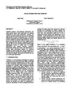
payload, whose swinging motion is exploited, and illustrates the conservative approach of using the load state ρ as a minimal distance constraint. We show the position and angle tracking data from the real world experiment (including an obstacle) in the left half of Fig. 4. Furthermore, we extended the approach to a horizontal obstacle to show the general validity and robustness of our algorithm. Both experiments are documented in the attached video. C. Payload Throwing Throwing a payload against a target requires reaching a certain release position and velocity. To do this, the quadrotor has to pump energy into the system by swinging it up and simultaneously going towards the optimal release point, as visible in Fig. 9. Note that during the whole maneuver the angle constraints between quadrotor and payload remain valid and the load is always at the limit (i.e., cable fully taut), due to unslung states being energetically less efficient (an intuitive justification is stated in the discussion V-B).
Furthermore, we expect the energy pumping to happen at the natural frequency of the pendulum due to the optimality of the trajectory. The natural pendulum frequency can be approximated as r r 9.806 sm2 1 g 1 ≈ 0.53 Hz. (18) fnat = = 2π l0 2π 0.88 m We conducted 10 throws for each target pt,1 , pt,2 (specified as in Sec.III-E) and analyzed the spectrum of the motion between the payload and the quadrotor (µ angle, cf. Fig. 10). As expected, most of the swinging motion takes advantage of the natural pendulum frequency. Figure 11 provides an analysis of the accuracy and precision of all throws, and showes the error and the corresponding error ellipses (RMS error along x,y-axes). D. Computation Time To prove the computation time advantage of our approach, we timed multiple executions of the optimization with both throwing setups and the rectangular waypoint flight setup (III-E, III-C), each with 5 randomly disturbed initial position configurations (±0.1 m on x, y, z) and 5 runs per configuration, giving 25 timing measurements per setup. A Lenovo Thinkpad 460p with Intel Core i7-6820HQ and 32 GB memory was used for the computation. The results are listed in Tab. IV-D. Our algorithm outperforms state-of-the-art approaches
Absolute Error in the Throwing Task
B. Optimality of Slung-only Trajectories
0.5
error y [m]
error target 1 error target 2
0
-0.5 -1.5
-1
-0.5
0
error x [m]
Fig. 11. Throwing results over 20 trials from two different distances to the target (represented as a black route). The blue and red dots represent the absolute error of the payload landing position with respect to the target, for the two different target distances, respectively. Similarly, the blue and red ellipses represent the error standard deviations.
For all problems shown in this paper, the optimizater found solutions where the payload was always at the cable limit (slung), which can be intuitively described as being the optimal solution for quadratic costs. This behavior is a consequence of the fact that during a slack-phase the payload accelerates downwards due to gravity and this acceleration must then be compensated at the moment when the payload becomes slung again. As a consequence of quadratic cost function (especially input cost R), compensation of the downward velocity component in finite time would always be worse than an solution where the cable is always taut. In both cases, the mean collective thrust required by the trajectory is the same, although the deviation and, therefore, the cost are higher in the case the cable becomes slack. C. Limitations
and is over 5 times faster in most comparable scenarios. For instance, in [25] the authors need more than 3000 s, using less than 60 nodes through the trajectory, for a waypoint navigation with obstacle avoidance task. They also computed simpler direct throwing trajectories in another experiment, with computation times around 100 s, where the trajectory did not include any longer swing-up (energy pumping) phase. Our framework takes on average less than 30 s for a comparable experiment using around 50 nodes. TABLE III C OMPUTATION T IME Experiment Throwing 1 Throwing 2 Triangle flight
mean [s] 24.83 9.86 50.24
std-dev. [s] 6.90 1.16 47.09
min/max [s] 16.99/36.17 7.82/10.96 16.19/140.43
Note that the throwing experiment 2 had a shorter distance to the target and therefore needed less complicated swinging maneuvers whereas the longer waypoint trajectory used more time nodes and therefore was tendentiously slower, with some outliers (∼ 140 s) due to the randomized initial state. V. D ISCUSSION A. Advantages Our approach is a general 3D-trajectory optimization algorithm capable of generating feasible trajectories that are not bounded to polynomials and obey all defined limits (constraints), while optimally achieving the stated goal in terms of the defined cost. The algorithm handles the payload throwing, waypoint navigation and obstacle avoidance task without the need for excessive cost tuning or setup of intermediate states, while maintaining the ability to adjust the costs depending on the desired trajectory properties. Our problem formulation benefits both the user and the solver, since it keeps the task description intuitive and the number of parameters low, while complexity scales only linearly with node number. Moreover, the inclusion of the full state vector allows a simple constraint formulation for goals and physical limitations of the platform (e.g. inputs, joint limits).
While we describe the payload dynamics in an efficient way, we neglect the state of the cable connecting the quadrotor and the payload, which might be advantageous for dynamic situations with excessive slack flight phases. Furthermore, the obstacle avoidance constraint that we present is non-convex and, thus, there are no guarantees that a feasible trajectory can be found if one exists – the optimization process could theoretically get stuck in a local minima. However, this never happened in our experiments. Nevertheless, a more general solution with guarantees to both of these problems is out of the scope of this paper and is currently being tackled in ongoing work. VI. C ONCLUSION In this paper, we proposed a method for parameterizing quadrotors with a slung payload using a complementarity constraint and show how this formulation, together with additional constraints from the robot, environment, or task, can be implemented in a non-linear optimization problem. Our contribution was twofold: (i) a novel dynamic model for a system composed of a quadrotor and a cable-suspended payload that does not require hybrid modes; (ii) a fast optimization implementation to compute energy-efficient, feasible, and safe trajectories for a variety of tasks. Our framework: (i) outperformed the state of the art in terms of speed, with significantly smaller computation times; (ii) provided a simple way of parameterizing different tasks; (iii) guaranteed the feasibility of the trajectory with respect to both the system dynamics and control input bounds. Our trajectory optimization algorithm typically needed less than 30 s on a simple laptop and could be used for fast planning of complex tasks. We experimentally validated our approach on a real quadrotor, showing that our method could easily generalize to a variety of tasks, such as flying through desired waypoints while avoiding obstacles, and throwing the payload toward a desired target. To the best of our knowledge, this was the first time that three-dimensional, agile maneuvers exploiting the full system dynamics have been achieved on quadrotors with a cable-suspended payload.
R EFERENCES [1] J. T. Betts. Survey of numerical methods for trajectory optimization. Journal of Guidance, Control, and Dynamics, 21(2):193–207, March 1998. ISSN 0731-5090. doi: 10.2514/2.4231. [2] P. J. Cruz, M. Oishi, and R. Fierro. Lift of a cablesuspended load by a quadrotor: A hybrid system approach. In IEEE Am. Control Conf. (ACC), pages 1887– 1892, July 2015. doi: 10.1109/ACC.2015.7171008. [3] C. De Crousaz, F. Farshidian, M. Neunert, and J. Buchli. Unified motion control for dynamic quadrotor maneuvers demonstrated on slung load and rotor failure tasks. In IEEE Int. Conf. on Robotics and Automation (ICRA), pages 2223–2229, 2015. doi: 10.1109/ICRA.2015. 7139493. [4] M. Faessler, F. Fontana, C. Forster, and D. Scaramuzza. Automatic re-initialization and failure recovery for aggressive flight with a monocular vision-based quadrotor. In IEEE Int. Conf. on Robotics and Automation (ICRA), pages 1722–1729, 2015. doi: 10.1109/ICRA. 2015.7139420. [5] A. Faust, I. Palunko, P. Cruz, R. Fierro, and L. Tapia. Learning swing-free trajectories for UAVs with a suspended load. In IEEE Int. Conf. on Robotics and Automation (ICRA), pages 4902–4909, 2013. doi: 10. 1109/ICRA.2013.6631277. [6] P. Gill, W. Murray, and M. A. Saunders. SNOPT: An SQP algorithm for large-scale constrained optimization. SIAM Rev., 47(1):99–131, January 2005. ISSN 00361445. doi: 10.1137/S0036144504446096. [7] F. Goodarzi, D. Lee, and T. Lee. Geometric stabilization of quadrotor UAV with a payload connected by flexible cable. IEEE Am. Control Conf. (ACC), September 2014. doi: 10.1109/ACC.2014.6859419. [8] M. E. Guerrero, D. A. Mercado, R. Lozano, and C. D. Garc´ıa. Passivity based control for a quadrotor uav transporting a cable-suspended payload with minimum swing. In IEEE Conf. on Decision and Control (CDC), pages 6718–6723, December 2015. doi: 10.1109/CDC. 2015.7403277. [9] C. R. Hargraves and S. W. Paris. Direct trajectory optimization using nonlinear programming and collocation. Journal of Guidance, Control, and Dynamics, 10(4):338– 342, 1987. doi: 10.2514/3.20223. [10] S. Kim, S. Choi, and H.J. Kim. Aerial manipulation using a quadrotor with a two DOF robotic arm. In IEEE/RSJ Int. Conf. on Intelligent Robots and Systems (IROS), pages 4990–4995, November 2013. doi: 10.1109/ IROS.2013.6697077. [11] K. Kondak, K. Krieger, A. Albu-Schaeffer, M. Schwarzbach, M. Laiacker, I. Maza, A. RodriguezCastano, and A. Ollero. Closed-loop behavior of an autonomous helicopter equipped with a robotic arm for aerial manipulation tasks. Int. J. of Advanced Robotic Systems, 10(2):145, 2013. doi: 10.5772/53754.
[12] T. Lee, M. Leok, and N. H. McClamroch. Nonlinear robust tracking control of a quadrotor UAV on SE(3). Asian Journal of Control, 15(2):391–408, 2013. ISSN 1934-6093. doi: 10.1002/asjc.567. [13] V. Lippiello and F. Ruggiero. Cartesian impedance control of a UAV with a robotic arm. IFAC Proceedings Volumes, 45(22):704–709, 2012. ISSN 1474-6670. doi: 10.3182/20120905-3-HR-2030.00158. 10th IFAC Symposium on Robot Control. [14] R. Mahony, V. Kumar, and P. Corke. Multirotor aerial vehicles: Modeling, estimation, and control of quadrotor. IEEE Robotics Automation Magazine, 19(3):20– 32, 2012. ISSN 1070-9932. doi: 10.1109/MRA.2012. 2206474. [15] D. Mellinger and V. Kumar. Minimum snap trajectory generation and control for quadrotors. In IEEE Int. Conf. on Robotics and Automation (ICRA), pages 2520–2525, May 2011. doi: 10.1109/ICRA.2011.5980409. [16] I. Palunko, R. Fierro, and P. Cruz. Trajectory generation for swing-free maneuvers of a quadrotor with suspended payload: A dynamic programming approach. In IEEE Int. Conf. on Robotics and Automation (ICRA), pages 2691–2697, 2012. doi: 10.1109/ICRA.2012.6225213. [17] I. Palunko, A. Faust, P. Cruz, L. Tapia, and R. Fierro. A reinforcement learning approach towards autonomous suspended load manipulation using aerial robots. In IEEE Int. Conf. on Robotics and Automation (ICRA), pages 4896–4901, 2013. doi: 10.1109/ICRA.2013.6631276. [18] P. O. Pereira, M. Herzog, and D. V. Dimarogonas. Slung load transportation with a single aerial vehicle and disturbance removal. In Mediterranean Conf. on Control and Automation, pages 671–676, June 2016. doi: 10.1109/MED.2016.7536040. [19] M. Posa and R. Tedrake. Direct trajectory optimization of rigid body dynamical systems through contact. In Algorithmic Foundations of Robotics X, pages 527– 542. Springer Berlin Heidelberg, 2013. doi: 10.1007/ 978-3-642-36279-8 38. [20] M. Posa, S. Kuindersma, and R. Tedrake. Optimization and stabilization of trajectories for constrained dynamical systems. In IEEE Int. Conf. on Robotics and Automation (ICRA), 2016. doi: 10.1109/ICRA.2016.7487270. [21] N. Ratliff, M. Zucker, J A. Bagnell, and S. Srinivasa. Chomp: Gradient optimization techniques for efficient motion planning. In Robotics and Automation, 2009. ICRA’09. IEEE International Conference on, pages 489– 494. IEEE, 2009. doi: 10.1109/ROBOT.2009.5152817. [22] R. Ruggiero, M.A. Trujillo, R. Cano, H. Ascorbe, A. Viguria, C. Perz, V. Lippiello, A. Ollero, and B. Siciliano. A multilayer control for multirotor UAVs equipped with a servo robot arm. In IEEE Int. Conf. on Robotics and Automation (ICRA), pages 4014–4020, May 2015. doi: 10.1109/ICRA.2015.7139760. [23] B. Siciliano, L. Sciavicco, and L. Villani. Robotics: modelling, planning and control. Advanced Textbooks in Control and Signal Processing. Springer, London, 2009.
ISBN 1-8462-8641-7. [24] K. Sreenath, N. Michael, and V. Kumar. Trajectory generation and control of a quadrotor with a cable-suspended load-a differentially-flat hybrid system. In IEEE Int. Conf. on Robotics and Automation (ICRA), pages 4888– 4895, 2013. doi: 10.1109/ICRA.2013.6631275. [25] S. Tang and V. Kumar. Mixed integer quadratic program trajectory generation for a quadrotor with a cablesuspended payload. In IEEE Int. Conf. on Robotics and Automation (ICRA), pages 2216–2222, 2015. doi: 10.1109/ICRA.2015.7139492. [26] R. Tedrake and the Drake Development Team. Drake: A planning, control, and analysis toolbox for nonlinear dynamical systems, 2016. URL http://drake.mit.edu. [27] B. Y¨uksel, G. Buondonno, and A. Franchi. Differential flatness and control of protocentric aerial manipulators with any number of arms and mixed rigid-/elastic-joints. In IEEE/RSJ Int. Conf. on Intelligent Robots and Systems (IROS), pages 561–566, October 2016. doi: 10.1109/ IROS.2016.7759109. [28] D. Zameroski, D. Starr, J. Wood, and L. Ron. Rapid swing-free transport of nonlinear payloads using dynamic programming. Journal of Dynamic Systems, Measurement, and Control, 130(4), 2008. ISSN 0022-0434. doi: 10.1115/1.2936384.