20th International Conference on Structural Mechanics in Reactor Technology (SMiRT 20) Espoo, Finland, August 9-14, 2009 SMiRT 20-Division-II, Paper 1864
Fatigue Crack Initiation and Crack Growth Studies for Pipes made of Carbon Steel Punit Arora, Suneel K Gupta, P.K. Singh, Vivek Bhasin, K. K. Vaze, A.K. Ghosh and H. S. Kushwaha Reactor Safety Division, Bhabha Atomic Research Center, Mumbai, 400085, India e-mail:
[email protected]
Keywords: Characteristic distance, low cycle fatigue, multiaxiality, fatigue crack growth
1
ABSTRACT
Experimental studies had been carried out to understand the behaviour of 8″ Sch.100 carbon steel (SA 333 Gr.6) notched pipes subjected to pure alternating bending moment using four point bend setup. The design rules as available in A-16 guide of RCC-MR for fatigue crack initiation were used to evaluate a characteristic distance (di) from the notch root at which the elastic plastic strain field would lead to experimentally obtained number of cycles for initiation. The 3D finite element analyses of actual pipes as under tested conditions are carried out to rule out approximations present in A-16 and compare di obtained from FE analysis with A-16 results. The characteristic distance parameter is further correlated with the damage caused by the combined effect of constraint and plastic strain available at a distance away from notch root. Further, the fatigue crack growth curves (a versus N) obtained from actual pipe tests are in good agreement with the analytical procedures as governed by Paris rule.
2
INTRODUCTION
The failure of the piping components may occur well below the allowable stress limits even under normal operating conditions. This confirms the presence of flaws which may have either gone undetected during pre-service inspection or appeared in due course of its service. Such failures need a detailed stress/ strain analysis to guarantee the component integrity under fatigue loading. Therefore, an alternate fail-safe design philosophy such as Leak-Before-Break (LBB) which is based on fracture mechanics concepts is adopted and requires rigorous integrity assessment of piping component with postulated part through thickness flaw. It is required to be demonstrated that the unstable tearing will never occur before the crack penetrates through thickness and gives easily detectable leakage. This requires investigation on fatigue crack initiation followed by fatigue crack growth (FCG) of piping components with different postulated part through flaws for the qualification of LBB design criterion. Additionally, fatigue crack initiation and crack growth data of actual piping components will be useful for the accurate life prediction of the older Nuclear Power Plants (NPP). In view of it, six numbers of tests were carried out by Singh et al (2003) on 8″ Sch.100 straight pipes having circumferential part through wall notch and made of carbon steel and subjected to pure alternating bending moment using four point bend setup. The material is similar to that used in primary heat transport (PHT) piping of Indian Pressurised Heavy Water Reactor (PHWR) and conforms to the specifications SA 333 Gr. 6 of ASME section II and section III. The aspect ratios (2c/a) of the notches are varied from 19 to 58 and the notch depth to thickness (a/t) ratio is varied from 0.125 to 0.4. The maximum remote stress is varied from 0.4σys to 0.7σys and the stress ratios (R) are 0.1 and 0.5. The Alternating Current Potential Drop (ACPD) technique has been used for evaluation of crack initiation and growth of notch front. The crack is taken to be initiated when it grows by 0.1 mm, this is due to the limitation in sensitivity of the instrument. The cycles to crack initiation in different tests range from 3000 to 320,000 and the cycles for crack to grow through wall fall in the range of 53000 to 869,000. Fatigue crack initiation has been widely studied in past using notched specimens by Neuber H. (1961), Topper et al. (1969), Hoffmann and Seeger (1985) to evaluate the local stress/ strain field from the stress/ strain concentration approach whereas Molski and Glinka (1981) applied equivalent energy density method 1
Copyright © 2009 by SMIRT 20
(ESED) to evaluate the same. This amplified local strain predicts the approximate number of cycles for crack initiation using low cycle fatigue curve. In this paper, an approximate methodology of A-16 guide for leak before break analysis and defect assessment of RCC-MRR which is based on evaluation the local stress and strain field based on stress/ strain concentration approach, is adopted. A16 requires strain calculations to be carried out at characteristic distance from the notch root to yield initiation life. This characteristic distance (di) is stated to be a material specific parameter by A-16 irrespective of the load applied and notch geometrical parameters. In view of this, characteristic distances are evaluated for all the six pipes using A-16 design procedure. The study is further extended using finite element analysis due to geometrical limitations in A-16 design procedure. Hence, the characteristic distances are evaluated from the actual state of stress and pipe geometry as under tested conditions. The comparison is made between the results obtained from FE analysis and A-16 design procedure for di. Fatigue crack growth as governed by Paris rule has been studied extensively using compact tension (CT) or three point bend (TPB) specimens by following ASTM E647. A similar set of experiments were carried on TPB specimens machined from the same pipe material by Singh et al. (2003) and the Paris constants were generated from the growth curves obtained. The ASME Boiler and Pressure Vessel Code Section XI also provides fatigue crack growth rate curves for carbon steel material under air environment based on small specimens. In this paper, a comparison has been made amongst the experimentally obtained fatigue crack growth curve (a versus N) and two analytical growth curves whose Paris constants are derived from two different sources which are experiments conducted on the specimens machined from the same material & the ASME Section XI.
3
EXPERIMENTAL DETAILS
Piping material All the tests were carried out on seamless pipes made of SA 333 Gr. 6 carbon steel material used in Indian PHWRs. The pipes were in normalized and tempered condition and conform to the specifications of ASME Section II and Section III. The chemical composition and tensile properties of the material are as tabulated in Table 1 and 2. Table 1. Chemical composition (in wt%) of pipe material C 0.14
Mn 0.9
Si 0.25
P 0.016
S 0.018
Al
Elastic Plastic strain Vs 'd'
0
10
20
30
40
50
60
EP Strain (FEM)
0.06 0.05 0.04 0.03 0.02 0.01 0 0
-6
'd' (distance from notch root) (10 m) ------>
10
20
30
40
50
60
'd' (distance from notch root) (10-6 m) ------>
(a)
(b)
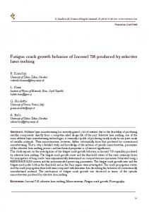
Figure 3. Variation of elastic-plastic strain amplitude as obtained from 2D FE analysis and A16 procedure with distance from notch root for (a) Plane stress, (b) Plane strain geometry However, the actual pipe cases where geometry also plays a major role can neither be attributed as completely plane strain nor plane stress as prescribed in the Creager’s formulae. It may be lying somewhere in between the two extreme cases. Therefore, detailed elastic plastic finite element analyses have been carried out for actual pipes under as tested conditions. One quarter domain of the test specimen was modeled using 20 noded 3D brick elements, with the finest mesh size of 20 μm near the point of singularity. The stabilized cyclic stress strain data for SA-333 Gr. 6 was used for the analysis (that is eqn 1). The LCF tests were conducted under uniaxial and completely reversible loading conditions. Hence, correction factors for mean stress (Morrow(1968)) and multiaxiality (Manson & Halford (1977)) have been accounted in the uniaxial Δε − N curve. The corrected fatigue failure curve is as given by eqn (4),
(%) Δε 2
= 100
(σ ′f ( M .F .) n − σ m ) E
′ (2 N i ) b + ε f ( M .F .)(2 N i ) c
(4)
′
where, σ ′f = 586.06 MPa, b = -0.0757, ε f = 24.06 %, c = -0.4814, n = 0.1523
σ m = mean stress (MPa) M.F. = e-0.5(TF-1)
; if TF ≥ 1.0
= 1.0
; if TF < 1.0
(5)
Triaxiality Factor (TF) = σh/ σeff = √2 (σ1+σ2+σ3)/{3[ (σ1-σ2)2 + (σ2-σ3)2 + (σ3-σ1)2 ]1/2}
(6)
σh = hydrostatic stress = (σ1+σ2+σ3)/3 σeff = effective stress (or von-mises stress) 5
Copyright © 2009 by SMIRT 20
= (1.0/√2)[ (σ1-σ2)2 + (σ2-σ3)2 + (σ3-σ1)2 ]1/2 σ1, σ2, σ3 = Three Principal Stresses Here, eqn (4) is the modified version of Basquin- Manson fit as given in eqn (2). It is well understood that the higher constraint reduces the ductility of the material. Therefore, an artificial penalty is imposed in the plastic strain part of the fatigue life curve to take care of the reduction in ductility. Table4. Comparison of characteristic distance as calculated from A-16 and 3D FE analysis. Specimen
a/t
2C/a
Pmax (kN)
R
Ni (Test data)
PBSC-8-1 PBSC-8-2 PBSC-8-3 PBSC-8-4 PBSC-8-5 PBSC-8-6
0.13 0.13 0.20 0.23 0.39 0.36
57 58 37 32 19 21
170 250 160,200 160 165,175 150
0.1 0.5 0.5 0.1 0.5 0.1
53000 320000 177000,58000 6000 32000,13000 3000
Characteristic distance di (μm) A-16 FEA 70 36 68 68 70 57 55 40 100 88 75 62
Thus, the number of cycles to crack initiation (Ni) can be calculated from corrected fatigue-failure curve using elastic-plastic strain amplitude as obtained from FE analysis at different ‘d’ distances from notch root. The distance at which the number of cycles corresponding to effective elastic plastic strain amplitude matches with the experimental value is taken as ‘characteristic distance(di)’. The characteristic distance is found to be varying between 36μm to 88 μm with mean value at 60μm as shown in Table 4. Further, the definition of ‘di’ has been analyzed in the context of some damage parameters like triaxiality factor (T.F.) in conjunction with plastic strain range (Δε p ) available at a distance from notch tip. The higher constraint in the form of T.F. suppresses the plasticity. The typical variations of T.F. and Δε p with distance from the root, are as plotted in Fig. 4. It can be observed that T.F. is maximum at around 100μm and the total equivalent plastic strain range almost vanishes at such distance. The results point to a critical / characteristic distance from the notch root where the material sees maximum damage and causes crack initiation. The variation of T.F. and Δε p depend upon load applied, notch geometrical parameters etc.
1.5 1.4 1.3 1.2 1.1 1.0 0.9 0.8 0.7 0.6 0.5 0.4 0.3 0.2 0.1 0.0
0.5
T.F. 0.4
0.3
0.2
Δεp(%)
Δεp(%)
T.F.
Therefore, it is difficult to comment di to be a material specific and treat variation in di as observed. However, this argument is based on the tests conducted till date on this material.
0.1
0.0 0
100
200
300
400
500
d (Dist from notch root) (in μm) Figure 4. FEA results: Typical variation of TF and % Δεp
5
FATIGUE CRACK GROWTH
6
Copyright © 2009 by SMIRT 20
Once the crack has initiated, the pipes were continued to be tested till the crack becomes through wall. The crack growth at different locations all along the notch length was recorded with number of cycles using ACPD technique. The FCG analytical study is carried out following Paris Law with two sets of material growth constants. One set of Paris constants has been derived from the FCGR tests conducted on TPB specimens (eqn 3), whereas the second set of constants have been obtained from ASME Sec XI for air environment. The experimental FCG data are found to be in reasonably close agreement with the analytical results for the first set of material growth constants (Fig. 5). PBSC-8-5(Analytical):R=0.5 PBSC-8-6(Analytical):R=0.1
PBSC-8-5(Expt):R=0.5 PBSC-8-6(EXPT):R=0.1
18
16
PBSC-8-1(Analytical):R=0.1
PBSC-8-2(Analytical):R=0.5
PBSC-8-1(Expt):R=0.1
PBSC-8-2(Expt):R=0.5
16 Max Crack Depth (mm)
max. Crack Depth (mm)
14 12 R=0.1
10 R=0.5
8 6 4
14 12 R = 0.1
10
R = 0.5
8 6 4
2 2
0 0
50000
100000
150000
200000
0
250000
0
N
200000
400000
600000
800000
1000000
N
(a)
(b) 16
PBSC-8-3(Analytical):R=0.5 PBSC-8-4(Analytical):R=0.1
PBSC-8-3(Expt):R=0.5 PBSC-8-4(Expt):R=0.1
Max Crack Depth (mm)
14 12 R = 0.1 10 R = 0.5 8 6 4 2 0 0
100000
200000
300000
400000
500000
600000
700000
N
(c)
Figure 5. Comparison of FCG test data of maximum crack depth with Paris Law governed crack growth using Paris constants derived from TPB specimens Similarly, the analytical maximum crack depth has been evaluated with respect to number of cycles using second set of Paris constants show the conservatism of ASME over experimental data (Fig. 6). PBSC-8-5(EXPT) PBSC8-6(EXPT)
PBSC-8-5(ASME) PBSC-8-6(ASME)
14 Max. crack depth (mm)
12 10 8 6 4 2 0 0
50000
100000
150000
200000
250000
N
Figure 6. Comparison of FCG test data of maximum crack depth with Paris Law governed crack growth using Paris constants as obtained from ASME Section XI
7
Copyright © 2009 by SMIRT 20
6
CONCLUSION
The experimental, analytical and FE study carried out on the CS pipes of outer diameter 219mm and 15.1 mm thickness concludes the followings for fatigue crack initiation and growth. 6.1
Fatigue Crack initiation
(a) A-16 procedure predicts the initiation life quite accurately for plane strain geometry, whereas it over predicts the life for plane stress condition. (b) Characteristic distance (di) as back calculated from A-16 and three dimensional finite element analysis, is found to have significant variation. The di is further analyzed in view of the damage caused by higher constraint effect and plastic strain available and concluded to be load and notch dimensions dependent parameter. However, this argument is based on the 6 tests conducted on CS pipes. (c) The initiation life is very large compared to expected number of cycles for a typical stress range in PHWR. 6.2
Fatigue crack growth
The analytical crack growth as governed by Paris law is in good agreement with the experimental growth data for the material growth constants derived from standard TPB specimens machined from the same piping material. The fatigue crack growth curve as specified in ASME Section XI produces conservative results.
REFERENCES Singh P.K., Vaze K.K., Bhasin V., Kushwaha H.S., Gandhi P., Ramachandra Murthy D.S., Crack initiation and growth behavior of circumferentially cracked pipes under cyclic and monotonic loading. Int J Pressure Vessel Piping 80(2003) 629-640. Neuber, H., “Theory of stress concentration for shear-strained prismatical bodies with arbitrary non-linear stress strain law,” Journal of Applied Mechanics, Transactions of ASME, Vol. 28, Dec. 1961; pp. 544-550. Topper, T.H., Wetzel, R.M. and Morrow, J., “Neuber’s rule applied to fatigue of notched specimens,” Journal of Materials, Vol. 4, No.1, March 1969, pp. 200-209. Hoffmann M., Seeger T., A generalized method for estimating multiaxial elastic plastic notch stresses and strains. Transactions of ASME, vol-107/1985, pp 250-260. Molski K, Glinka G. A method for elastic–plastic stress and strain calculation at a notch root. Mater Sci Eng 1981;50(1):93-100. A16 guide for defect assessment and leak before break analysis. Edition 2002. E647-93, Standard test method for measurement of fatigue crack growth rate. Annual book of ASTM standard, vol. 03.01.; 1995. pp. 569–96. Rules for in-service inspection of nuclear power plant components. ASME Boiler and Pressure Vessel Code, Section XI, New York;2001. E606-93, “A standard practice for strain controlled fatigue testing” Annual book of ASTM standards, vol. 03.01, 1995. Mendelson A., Plasticity theory and applications, 1968. Moulin D., Roche R.L., Correction of the Poisson effect in the elastic analysis of Low-cycle fatigue, Int. J. Pres. Ves. & Piping 19 (1985), 213-233. Manson S.S. & Halford G.R., (1977), Multiaxial low cycle fatigue of Type 304SS. Journal of Engineering Material Technology, pp 283-285. Morrow J., Fatigue design handbook, Advances in engineering, vol. 4, Society of Automotive Engineers, Warrendale, Pa., 1968, sec. 3.2, pp 21-29. 8
Copyright © 2009 by SMIRT 20