Nov 12, 2016 - Laser stake-welded steel sandwich panels are widely used in engineering due to their high ... as square tubes, C- [10â11] and Z- [12â13] profiles etc.; see Fig. ..... [1] C. Libove, R.E. Hubka, Elastic Constants for Corrugated-Core Sandwich Plates, NACA TN .... terface fracture of stainless steel-epoxy bonds.
Materials and Design 115 (2017) 64–72
Contents lists available at ScienceDirect
Materials and Design journal homepage: www.elsevier.com/locate/matdes
Fatigue strength of laser-welded foam-filled steel sandwich beams Anssi T. Karttunen a,⁎, Mikko Kanerva a,b, Darko Frank a, Jani Romanoff a, Heikki Remes a, Jasmin Jelovica a, Sven Bossuyt a, Essi Sarlin b a b
Aalto University, Department of Mechanical Engineering, P.O. Box 14300, 00076 Aalto, Finland Tampere University of Technology, Department of Materials Science, P.O. Box 589, 33101 Tampere, Finland
H I G H L I G H T S
G R A P H I C A L
A B S T R A C T
• Hybrid sandwich beam is developed on the basis of reduced J-integral value at weld notch tips. • Polymeric foam bonded to the voids of webcore beams increases weight only by 6%. • Filled beams are tested in three-point bending for stiffness, ultimate strength and fatigue. • Filled beams outperform empty ones by a factor of 8.5 in terms of load level at 2 million cycles.
a r t i c l e
i n f o
Article history: Received 14 September 2016 Received in revised form 4 November 2016 Accepted 10 November 2016 Available online 12 November 2016 Keywords: Sandwich panels Ultimate strength, fatigue strength Hybrid structure Scanning electron microscopy
a b s t r a c t Laser stake-welded steel sandwich panels are widely used in engineering due to their high stiffness-to-weight ratios. The welds are thinner than the plates they join so that there are two crack-like notches on each side of a weld. As a consequence, the welded joints are susceptible to fatigue. In this study, as a remedy to the fatigue problem, low-density H80-grade Divinycell polyvinylchloride foam is bonded adhesively to the voids of stakewelded web-core sandwich beams. The foam reduces shear-induced stresses in the stake-welds. The choice of Divinycell H80 is founded on earlier J-integral-based finite element fatigue assessments of sandwich panels. Empty and the H80-filled sandwich beams are tested in three-point-bending for stiffness, ultimate strength and fatigue (load ratio R = 0.05). The failure modes in the weld joint region are studied using scanning electron microscopy. The experimental results show that the filling increases the stiffness of the sandwich beams by a factor of three while the weight is increased only by 6%. The ultimate strength is increased by 2.7 times. As for the fatigue behavior, the slope increases from m = 4.508 of empty panels to m = 7.321 of filled panels while the load level at 2 million cycles increases by a factor of 8.5. © 2016 Elsevier Ltd. All rights reserved.
1. Introduction
⁎ Corresponding author. E-mail address: anssi.karttunen@aalto.fi (A.T. Karttunen).
http://dx.doi.org/10.1016/j.matdes.2016.11.039 0264-1275/© 2016 Elsevier Ltd. All rights reserved.
Demand for recyclable, light, safe and modular plate structures stimulates the study of novel structural solutions for transportation and civil engineering. Steel sandwich panels with structural cores offer an option to fulfill these requirements. Low-density cores of sandwich panels can
A.T. Karttunen et al. / Materials and Design 115 (2017) 64–72
Nomenclature C E F ΔJ m Nf R ν SED SEM
material constant used in S-N curve Young's modulus force J-integral range slope of fatigue resistance curve number of cycles to failure load ratio Poisson ratio Strain Energy Density scanning electron microscopy
65
be constructed from different types of bended plate profiles, e.g. corrugations, X- and hat-profiles [1–9], or from manufactured sections such as square tubes, C- [10–11] and Z- [12–13] profiles etc.; see Fig. 1. The joining of these panels can be done by bolting or riveting [4], adhesive bonding [2,7] or by spot- [3] or laser-stake welding [16]. Web-core (or I-core) sandwich panels have the simplest core topology [14–24]. These panels have high stiffness-to-weight and stiffnessto-strength ratios. In addition, the uni-directional, hollow cores can be used for system integration (e.g. air-conditioning, cabling); see for example Ref. [25]. The potential of web-core sandwich panels can be exploited fully only when all limit states have been accurately assessed, i.e. fatigue, buckling, ultimate and accidental limit states. Once these are known, optimization can be used to find the best structural solutions for a given application; see Refs. [25–29].
Fig. 1. Top: Laser-welded steel sandwich panels, picture adapted from [30]. Bottom: reduction of shear-induced local stresses due to filling material (Divinycell grades H80 and H200, [31]).
66
A.T. Karttunen et al. / Materials and Design 115 (2017) 64–72
A laser-welded T-joint of a web-core sandwich panel has two cracklike notches on each side of it because the weld thickness is significantly smaller than the web plate thickness. When a web-core panel bends, the shear deformation opposite to the web direction causes local bending of the joined plates in the vicinity of a welded T-joint. This leads to tension at one notch tip and compression at the other. A fatigue crack initiates at the tensile tip and propagates through the weld under cyclic loading until the plates are separated and the sandwich effect is lost [32–34]. The crack-like notches essentially determine the fatigue strength of the joints and panels and, thus, form design constraints in dynamically loaded structures such as ships and bridges particularly in locations where shear forces have high gradients, for example, near point loads and plate edges [20–21,35]. The utilization of local approaches for fatigue assessment (for overview see Ref. [36]) requires accurate stress and strain fields around the critical notch tip. It was shown in Ref. [32] that a J-integral-based local finite element approach is suitable for the fatigue assessment of laser stake-welded T-joints. This approach originates from the works of Lazzarin, Berto and co-workers in Refs. [37–39] where the idea is to assess the J-integral or Strain Energy Density (SED) at the notch tip. This approach has been successfully applied to model the results from fatigue experiments in Refs. [32–34]. with ΔJ as fatigue strength parameter and in Ref. [40] using the SED-concept. It has been observed that the J-integral-based fatigue resistance curves can have slope values between 4 and 8, depending on the loading condition [34]. It was also demonstrated that different loading conditions cause different concentrations of the maximum principal stress at the critical notch tip and that the slope value appears to depend on the concentration level. In order to control the fatigue life, the loading experienced by the stakeweld can be affected, for example, by using a filling material [31,34]. This reduces the shear-induced stresses and deformations near the laser-stake-welds (See Fig. 1) and, further, the J-integral value at the notch tip. In general, the requirement for sandwich panels in structural applications designed for 10–20 years is that they must withstand more than 100,000 loading cycles, which is to say, the high-cycle fatigue regime is of primary interest. In this paper, we develop a web-core sandwich structure with improved fatigue strength by bonding polymeric foam to the voids of a steel web-core beam. Two-stage finite element analyses results from Ref. [30] with the J-integral as the fatigue strength parameter show the fatigue strength improvement against Young's modulus and filling material's mass. The selection of the foam and adhesive is performed on the basis of the static as well as fatigue strength of the individual components. Based on the analysis, foam-filled beams for experiments are specified and manufactured. The beams are tested under threepoint-bending for stiffness, ultimate strength and fatigue. The failure modes are studied using scanning electron microscopy (SEM). Finally, some discussion and conclusions on the structural concept are given.
2. Materials and methods 2.1. Selection of filling material Two-stage finite element analyses considering first the panel response and then the T-joint through sub-modeling were performed in Ref. [30] assuming linear elastic material models. The main idea was to decrease the stress levels and furthermore the J-integral values at the crack tips using different filling materials. The utilized finite element modeling approach did not consider the multimaterial steel-adhesivefoam interface in detail. The steel was modeled using Young's modulus E = 206,000 MPa and Poisson ratio ν = 0.3. The filling material was selected from various options by using the manufacturer values for density, Young's modulus and Poisson ratio. Geometrical nonlinearity was employed in the computations. The fatigue life of the laser-stake weld pffiffiffiffiffiffi m was assessed using the relation N f ð ΔJ Þ ¼ C with m = 9.1 and C =
294 MPa4.55 mm4.55. The fatigue strength improvement due to each filling material can be seen in Fig. 2A and B as a function of added mass and the Young's modulus of the filling material, respectively. By requiring that the filling increases the fatigue life of a sandwich panel significantly, and that a laser-stake-welded steel joint should always fail before the foam, Divinycell H80 is selected here as the filling material for the experiments.
2.2. Test specimen preparation Each web-core sandwich beam specimen was 50 mm wide, 46 mm in height and consisted of four unit cells with a web-spacing of 120 mm resulting in an effective total length of 480 mm; see Figs. 3A and 4. The nominal thicknesses of the face and web plates were 3.0 and 4.0 mm, respectively. The face plate material was S355J2G2 structural steel and the web plates were manufactured from S235JR. The face and web plates were joined by laser-welding. The resulting weld thickness was 0.3–2 mm. In addition to the specimens with empty cells, web-core beams with Divinycell H80 as the filling material were tested. Divinycell is a polyvinylchloride-based rigid cellular foam with a closed micro-cell structure. The H80-grade has a density of 80 kg/m3. Blocks of Divinycell foam were cut using a circular saw and cleaned using pressurized air and ethanol; see Fig. 3A. Before adhesion, the voids of the web-core beams were surface-treated; see Table 1 and Fig. 3B. The Divinycell blocks were bonded to the voids of the beams by adding an adhesive both on the beam surfaces (Fig. 3C) and the Divinycell blocks (Fig. 3D). Room temperature curing, particletoughened epoxy-based paste adhesive (DP190, 3M) was selected due to its high shear strength (9.6–17.2 MPa; Ref. [41]). The filled webcore beams were cured overnight (22 ± 3 h) at room temperature (20.4 ± 2 °C, 60 ± 15%RH). Finally, the bonds were post-cured in an air-circulating digital oven for 4 h (80 ± 2 °C). Bond thicknesses of 1– 3 mm were achieved for the steel-foam interfaces. The weights of the empty and filled beams were 1598 g (±30 g) and 1695 g (±14 g), respectively, indicating a 6% (97 g) increase for the filled ones. Of the exact weight gain, the Divinycell blocks covered approximately a half (4 × 16 ± 1 g) and adhesive the other half (70 g).
2.3. Test setup for quasi-static and fatigue testing The static and fatigue tests were carried out using a servo-hydraulic universal testing machine. The used three-point bending test setup is presented schematically in Fig. 4. The ends of the beam specimen rest on roller supports and the beam is subjected to a load exerted by a cylindrical indenter in the middle. Both the indenter and the supports have grooves to accommodate the faces of the stake welds. Force and displacement gauges are attached to the driving cylinder so that both force- and displacement-controlled tests can be performed. The displacement of the web-core beam is measured by a displacement gauge in contact with the bottom face plate. Eight strain gauges were attached to each specimen in the manner depicted in Fig. 4. The stiffness and ultimate strength tests were displacementcontrolled. Ultimate strength tests were carried out for one empty specimen and for one H80 specimen to observe the transition from elastic to plastic behavior, and to determine the load-carrying capacity and failure modes of the specimens. The plastic behavior of the specimens was tracked incrementally by loading and unloading the specimens during the tests. A constant displacement rate of 10 mm min−1 was used at all times. The fatigue tests were force-controlled. Altogether nine empty and eight H80-filled specimens were tested. A load ratio of R = 0.05 was used. For empty specimens the loading frequency was 5 Hz, whereas for the H80 specimens a more conservative frequency of 3 Hz was chosen to avoid the heating and softening of the filling material [42].
A.T. Karttunen et al. / Materials and Design 115 (2017) 64–72
67
Fig. 2. Selection of test specimen filling material based on the fatigue life of a sandwich panel with different polymeric foams as function of A) filling material mass and B) Young's modulus. For more details on the estimated fatigue lives of sandwich panels with different filling materials, see Table 2 in Ref. [30].
2.4. Fracture surface analysis The fracture surfaces were studied via field-emission scanning electron microscopy (SEM) using model ULTRAplus (Zeiss). The samples for
SEM were extracted from the test specimens using a circular diamond saw and then embedded into molding epoxy. Sample surfaces were polished and vacuum sputtering was applied for gold coating. The penetration of the adhesive into the web-face plate joints was studied using
Fig. 3. Specimen preparation: A) pre-cut parts of the steel sandwich panels and Divinycell blocks, B) removing grease with acetone bath, applying adhesive on C) steel and D) Divinycell blocks.
68
A.T. Karttunen et al. / Materials and Design 115 (2017) 64–72
Fig. 4. Schematic presentation of the three-point bending test setup. The distance dc between the center of a 5 mm long strain gauge and the edge of a web plate was for the static and fatigue specimens 7 and 9 mm, respectively. The latter value allowed an easier installation of the gauges.
a visual light microscope (MZ 7.5, Leica Microsystems) and samples were extracted from the test specimens after fatigue failure and ultimate static loading. 3. Results 3.1. Static tests Fig. 5 shows that strains calculated using a finite element model modified from that of Ref. [30] are in good agreement with the corresponding strains measured from an empty beam. Fig. 6A shows the force-displacement curves from the static tests of the empty and H80 specimens. The linear elastic regions indicate that the overall stiffness of the H80 specimen is approximately three times that of the empty specimen; the stiffening of the H80 specimen is caused by an increase in core shear stiffness. In the plastic region, the welded joints of the specimens do not break but plastic hinges form around them. The empty specimen can carry a load of 2.5 kN. The H80 specimen loses its load-carrying capacity essentially at 6.8 kN when the filling material breaks near one of the web plates. The failure mode of the H80 specimen is shown in Fig. 6B. Before the failure, plastic hinges have formed below the indenter and around the joints near the failure. The plastic hinges formed similarly in the case of the empty specimen. 3.2. Fatigue tests Fig. 7 summarizes the fatigue test results, while the numerical values and failure modes of each specimen are given in detail in Table 2. In the fatigue tests, any of the welded joints may break due to shear-induced local bending at stake-welds with the exception of the two joints in the middle. The middle web plate does not warp and, thus, the stakewelds in it do not experience bending stresses. Fig. 7A presents the maximum displacements for two of the tested beams during a fatigue test. The border between crack initiation and growth for the empty specimen is not meant as an exact one. The point is that once the cracks in the joints start to grow to a notable extent, the joints become weaker and the specimen starts to lose its overall stiffness, which is manifested by the exponential growth of the maximum displacement. The cracks grow from the tensile side in each joint and, ultimately, a joint fails (loss of structural integrity) which is indicated by a discontinuity that determines the fatigue life. In the empty specimens multiple joints
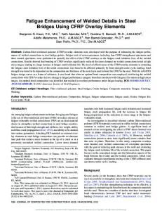
typically fail simultaneously. Fig. 7B shows that the fatigue strengths of the empty and filled panels at two million cycles are F = 220 N and F = 1860 N, respectively. Meanwhile the slope changes from m = 4.508 to m = 7.321. The failure of a H80 fatigue specimen (Fmax = 3 kN) is considered in detail in Fig. 8. Fig. 8A shows the fatigue failure at a bottomside joint of the specimen. At the same instance when the weld failed, the filling material cracked approximately in an angle of 45 degrees (shear) with respect to the faceplates. Notable plastic deformations did not occur at this stage. After the fatigue test, a static load (F = 4 kN) has been exerted on the same specimen in Fig. 8B. The additional static load results in the failure of the topside weld as well. When the topside weld fails, the interfaces between the H80 and face plates open up and this is accompanied by large plastic deformations. 3.3. Fracture surfaces and crack path The failure of the T-joints, namely the fracture of the laser weld and adhesive, was studied by the aid of the fracture surfaces of failed laser welds (see Fig. 9A for fracture surface at joint, Point A) to characterize the welds and the different fatigue failure mechanisms in the beams. Optical images of the fracture surface (Point A) indicated that a typical weld extended approximately 1.4 ± 0.02 mm in the thickness direction of the web plate at the joint, as shown in Fig. 9B–D. Based on the web plate thickness (4 mm), the measured weld thickness gives a notch length of 0…2.6 mm depending on the exact location of the weld seam. The measured weld thicknesses agree with the values found in the current literature for similar structures [23] and the weld location (determining the notch length) covered the limiting conditions of weld at the plate edge and in the middle [23]. For the filled specimens in this study, the adhesive used to adhere the filling can penetrate into the notches at joints, and possibly affect the joint behavior. An estimate of the adhesive penetration between the face and web plate and the joint was made based on the observed tip of the adhesive residues on fracture surfaces (see Fig. 9B, Point A) and the known web plate thickness giving an average of 370 μm (±150 μm). Therefore, based on the microscopy on the fracture surfaces at joints, the penetration of the paste adhesive is low, thus, the influence on the joint behavior minor. However, already a small amount of adhesive inside the notch prevents it from fully closing making it difficult to ignore the adhesive as a factor for extended fatigue life. The final failure of a filled beam involved debonding of the web plate from the face plate at the joint (see Fig. 9A, Point A) and subsequent crack propagation towards the interface between the face plate and filling (see Fig. 9A, Point B). To verify the quality of the adhesive bonding with filling material (i.e. the Divinycell block), the meso-scale failure mode at the interface region was studied. For this, SEM imaging was performed for locations where it was difficult to visually identify cohesive failure, i.e., that the fracture had occurred cohesively inside the filling. Based on the SEM imaging (see Fig. 10A and B), the failure mode along the face plate-filling interface was observed to be essentially cohesive; the crack had propagated inside the filling material. In more detail, the cross-sectional imaging verified that Divinycell cell wall material was left on adhesive. Voids, namely trapped air with a spherical shape and diameter ≈ 50 μm, were found in bulk adhesive but no micro-cracks had initiated at these voids.
Table 1 Surface treatment procedure of the steel beams prior to adhesive bonding. Treatment
Action
Medium
Temperature
Duration
Dehydration Degrease #1 Degrease #2 Roughening and cleaning (oxides, rust)
Vacuum oven Wiping Immersion Grit blasting (4.5 bar, ≈45°) Immersion
Air (0.5 ± 0.05 bar) Acetone Ethanol Aluminum oxide (Duralum, white, Ref-200) Ethanol
50–70 °C Ambient Ambient Ambient
18–24 h – 15–30 min ≈5 min
Ambient
10–20 min
Rinsing
A.T. Karttunen et al. / Materials and Design 115 (2017) 64–72
69
Fig. 5. Strains from gauges G1–G4 (see Fig. 4) of an empty beam.
Fig. 6. A) Force-displacement curves of the static empty and H80-filled specimens. For the filled specimen only the first loading/unloading cycle is shown in full. B) Failure of the H80-filled specimen in the static test. The filling material breaks near the web plate to the left from the indenter and the rupture goes throughout the width of the specimen.
Moreover, the condition at the interface between the face plate steel and the epoxy layer (Point B) was studied to verify the quality of the adhesive bonding on steel. Based on SEM imaging at the steel-epoxy interface (see the magnifications in Fig. 10C and D) it was noted that no observable damage, such as cracks or crazes, was found in the adhesive layer. The interface was mostly intact and the adhesive had essentially wetted the roughness of the steel surface. On a microscale, local debonding was occasionally present but it might have formed due to the sample cutting for microscopy.
In summary, the fracture surface analysis verified that the adhesive bonding is not the weak point during fatigue loading of the sandwich beams – the fatigue failure initiates at the laser welded joints between the face and web plates and the final rupture follows due to crack propagation into the filling material. Also, some adhesive was found between the face plate and web plate at the weld notch, which means that the adhesive might have affected the fatigue performance of the filled beams. It is worth noting that the interfacial behavior and response of the adhesive is strongly affected by environmental conditions
Fig. 7. A) Displacement history from two different fatigue tests, see Empty 2 and Filled 4 in Table 2. B) Fatigue strength from experiments. The slopes and scatter range indices related to 10–90% probabilities of survival are given.
70
A.T. Karttunen et al. / Materials and Design 115 (2017) 64–72
Table 2 Fatigue data. Failure locations: IT/IB = Intermediate Top/Bottom joint between indenter and roll support. ST/SB = Support Top/Bottom joint. Load ratio was R = 0.05. Specimen ID
Fmax [N]
Cycles to failure
Failure location
Empty 1 Empty 2 Empty 3 Empty 4 Empty 5 Empty 6 Empty 7 Empty 8 Empty 9 Filled 1 Filled 2 Filled 3 Filled 4 Filled 5 Filled 6 Filled 7 Filled 8
264 290 320 350 350 375 400 400 450 1000 2250 2250 2500 2500 2750 2750 3000
1,204,000 281,200 496,200 388,500 201,400 136,900 147,300 183,000 64,500 2,590,000 435,500 590,200 209,600 265,700 74,300 137,100 70,500
ST & SB IT & SB IT & SB IB & SB IT & SB IT & SB IT & SB IT IT & SB (Runout) IB IB IB IB IB IB & IT IB
[43,44] so that testing at elevated temperature and wet conditions shall be conducted in future studies.
4. Conclusions This paper presented an investigation on the fatigue strength of empty and foam-filled laser-welded steel sandwich beams. The beams were tested under 3-point-bending for stiffness, ultimate strength and fatigue. In the fatigue tests, the failure mode was crack propagation at the laser-stake welds and finally cohesive fracture in the foam. The results are in agreement with Ref. [31] in terms of static and ultimate strength, but the fatigue life improvement is far better than expected; the load level at 2 million cycles increases by a factor of 8.5 when the beams are filled with a low-density polyvinylchloride foam (Divinycell H80). This is a clear indication that the filling technology is a very effective way to improve the fatigue strength of lightweight sandwich panels. This means that the order of limit states needs to be reconsidered in design.
Fig. 8. A) Fatigue failure of a bottomside weld. B) Additional static load causes the failure of the topside weld as well and the separation of the interfaces after fatigue failure.
Fig. 9. Fracture surfaces and crack path after fatigue testing: A) Points of sample extraction for microscopy analyses (compare with Fig. 8B). B) Weld fracture surface and adhesive penetration at the face-web plate joint by visual light microscopy at Point A. C) Fracture surface on weld. D) Weld fracture surface at the face-web plate joint by visual light microscopy and for another analysis location.
A.T. Karttunen et al. / Materials and Design 115 (2017) 64–72
71
Fig. 10. Cross-sectional SEM imaging at Point B: A) Typical cross-section of the crack path at adhesive-filling interface (crack propagated from right to left). B) Typical cross-section of the crack path at adhesive-filling interface for another analysis location. C) Magnified image of the interface between steel and adhesive. D) Magnified image of the microscale interface between steel and adhesive.
The fatigue problems in laser-welded web-core sandwich panels are due to shear-induced warping and these deformations are often very local in the plate domain. Thus, it is recommended that the filling of a sandwich panel is carried out only at the locations of high out-ofplane shear opposite to the web-plate direction. However, before such functional grading can be done one must be able to explain the underlying physics of crack propagation in three-dimensional plate structures. Therefore, it is recommended that large panels should be tested next. Finite element analysis in relation to the fatigue test results of the present paper was not performed due to the fact that the modeling of the multimaterial interface would require cyclic properties of all the constituent materials and the actual thickness of the adhesive layer just to mention a few challenges. The finite element analysis is left for future work. Acknowledgements The work carried out in this study was mainly financed by the Department of Mechanical Engineering of Aalto University, Espoo, Finland. Financial support was also received from Academy of Finland project ‘Fatigue Strength of Laser-Welded Steel Sandwich Plates’ (Decision No.261286). All support is gratefully appreciated. References [1] C. Libove, R.E. Hubka, Elastic Constants for Corrugated-Core Sandwich Plates, NACA TN 2289, Langley Aeronautical Laboratory, Langley Field, Va, 1951. [2] J.D. Clark, Predicting the properties of adhesively bonded corrugated core sandwich panels, Second International Conference Adhesion '87, York University, UK, September 7–9 1987, pp. W1–W6. [3] C. Norris, Spot Welded Corrugated-core Steel Sandwich Panels Subjected to Lateral Loading(Ph.D. Thesis) University of Manchester, 1987. [4] P.K.H. Tan, Behaviour of Sandwich Steel Panels Under Lateral Loading(Ph.D Thesis) University of Manchester, 1989.
[5] C.J. Wiernicki, F. Liem, G.D. Woods, A.J. Furio, Structural analysis methods for lightweight metallic corrugated core sandwich panels subjected to blast loads, Nav. Eng. J. (May 1991) 192–203. [6] T.A. Marsico, P. Denney, A. Furio, Laser-welding of lightweight structural steel panels, Proceedings of Laser Materials Processing Conference, ICALEO 1993, pp. 444–451. [7] E.M. Knox, M.J. Cowling, I.E. Winkle, Adhesively bonded steel corrugated core sandwich construction for marine applications, Mar. Struct. 11 (1998) 185–204. [8] J.D. Poirier, S.S. Vel, V. Caccese, Multi-objective optimization of laser-welded steel sandwich panels for static loads using a genetic algorithm, Eng. Struct. 49 (2013) 508–524. [9] L. Valdevit, Z. Wei, C. Mercer, F.W. Zok, A.G. Evans, Structural performance of near-optimal sandwich panels with corrugated cores, Int. J. Solids Struct. 43 (2006) 4888–4905. [10] T.C. Fung, K.H. Tan, T.S. Lok, Analysis of C-core sandwich plate decking, Proceedings of the Third International Offshore and Polar Engineering Conference, Singapore, June 6–11 1993, pp. 244–249. [11] T.C. Fung, K.H. Tan, T.S. Lok, Shear stiffness DQy for C-core sandwich panels, J. Struct. Eng. 122 (8) (August 1996) 958–965. [12] T.C. Fung, K.H. Tan, T.S. Lok, Elastic constants for Z-core sandwich panels, J. Struct. Eng. 120 (10) (October 1994) 3046–3055. [13] T.C. Fung, K.H. Tan, Shear stiffness for Z-core sandwich panels, J. Struct. Eng. 124 (7) (July 1998) 809–816. [14] Å. Holmberg, Shear-weak Beams on Elastic Foundation, 10, IABSE Publications, 1950 69–85. [15] Y.N. Chen, D. Ranlet, J. Kempner, Web-stiffened sandwich structures, J. Appl. Mech. (December 1971) 964–970. [16] F. Roland, T. Reinert, Laser Welded Sandwich Panels for the Shipbuilding Industry, Lightweight Construction – Latest Developments, February 24–25, 2000 1–12 (London, SW1). [17] A. Klanac, P. Kujala, Optimal design for steel sandwich panel applications in ships, The Proceedings of The Ninth International Symposium on Practical Design of Ships and Other Floating Structures, Lübeck-Travemunde, September 12–17 2004, pp. 907–914. [18] H. Kolsters, D. Zenkert, Numerical and Experimental Validation of Stiffness Model for Laser-Welded Sandwich Panels with Vertical Webs and Low Density Core, Presented in: Hans Kolsters, Licentiate Thesis - Paper B, Kunliga Tekniska Högskolan, Stockholm, 2002. [19] T.S. Lok, Q. Cheng, L. Heng, Equivalent stiffness parameters of truss-core sandwich panels, Proceedings of the Ninth International Offshore and Polar Engineering Conference, Brest May 30–June 4, 1999, pp. 292–298. [20] J. Romanoff, P. Varsta, H. Remes, Laser-welded web-core sandwich plates under patchloading, Mar. Struct. 20 (1–2) (2007) 25–48. [21] J. Romanoff, P. Varsta, Bending response of web-core sandwich plates, Compos. Struct. 81 (2) (2007) 292–302. [22] C.R. Briscoe, S.C. Mantell, T. Okazaki, J.H. Davidson, Local shear buckling and bearing strength in web core sandwich panels: model and experimental validation, Eng. Struct. 35 (February 2012) 114–119. [23] J. Romanoff, H. Remes, G. Socha, M. Jutila, P. Varsta, The stiffness of laser stake welded Tjoints in web-core sandwich structures, Thin-Walled Struct. 45 (4) (2007) 453–462.
72
A.T. Karttunen et al. / Materials and Design 115 (2017) 64–72
[24] J. Jelovica, J. Romanoff, S. Ehlers, P. Varsta, Influence of weld stiffness on the buckling strength of laser-welded web-core sandwich plates, J. Constr. Steel Res. 77 (2012) 12–18. [25] L. Valdevit, J.W. Hutchinson, A.G. Evans, Structurally optimized sandwich panels with prismatic cores, Int. J. Solids Struct. 41 (2004) 5105–5124. [26] K. Kalnins, E. Skukis, J. Auzins, Metamodels for I-core and V-core sandwich panel optimization, Proceedings of 8th International Conference on Shell Structures: Theory and Applications, SSTA-05, Jurata October 12th–14th 2005, pp. 569–572. [27] S. Ehlers, A procedure to optimize ship side structures for crashworthiness, Journal of Engineering for the Maritime Environment 224 (2010) 1–11. [28] J. Romanoff, P. Kujala, Optimum design for steel sandwich panels filled with polymeric foam, Proceedings From 6th International Conference on Fast Sea Transportation, Vol. 3, Southampton 2001, pp. 197–205. [29] H. Kolsters, P. Wennhage, Optimisation of laser-welded sandwich panels with multiple design constraints, Mar. Struct. 22 (2) (April 2009) 154–171. [30] Frank, D., Romanoff, J. and Remes, H., Fatigue life improvement of laser-welded web-core steel sandwich panels using polymer-based filling materials, IIW Document XIII-2598-15. [31] J. Romanoff, Periodic and homogenized bending response of faceplates of filled web-core sandwich beams, Compos. Struct. 113 (July 2014) 83–88. [32] D. Frank, H. Remes, J. Romanoff, J-integral-based approach to fatigue assessment of laser stake-welded T-joints, Int. J. Fatigue 47 (2013) 340–350. [33] D. Frank, J. Romanoff, H. Remes, Fatigue strength assessment of laser stake-welded webcore steel sandwich panels, Fatigue Fract. Eng. Mater. Struct. 36 (8) (2013) 724–737. [34] D. Frank, H. Remes, J. Romanoff, On the slope of the fatigue resistance curve for laser stakewelded T-joints, Fatigue Fract. Eng. Mater. Struct. 36 (12) (2013) 1336–1351.
[35] H.N.G. Wadley, T. Børvik, L. Olovsson, J.J. Wetzel, K.P. Dharmasena, O.S. Hopperstad, V.S. Deshpande, J.W. Hutchinson, Deformation and fracture of impulsively loaded sandwich panels, J. Mech. Phys. Solids 61 (2) (February 2013) 674–699. [36] D. Radaj, C.M. Sonsino, W. Fricke, Fatigue Assessment of Welded Joints by Local Approaches, second ed. Woodhead Publishing, Cambridge, UK, 2006. [37] Z. He, A. Kotousov, F. Berto, Effect of vertex singularities on stress intensities near plate free surfaces, Fatigue Fract. Eng. Mater. Struct. 38 (7) (2015) 860–869. [38] F. Berto, A. Campagnolo, P. Lazzarin, Fatigue strength of severely notched specimens made of Ti-6Al-4V under multiaxial loading, Fatigue Fract. Eng. Mater. Struct. 38 (5) (2015) 503–517. [39] F. Berto, Tilted lateral V-notches with root hole subjected to in-plane mixed mode loading: fictitious notch rounding concept, Mater. Des. 89 (2016) 913–927. [40] D. Frank, Fatigue strength assessment of laser stake-welded T-joints using local approaches, Int. J. Fatigue 73 (April 2015) 77–87. [41] Technical Data Sheet, Scotch-Weld Epoxy Adhesives, DP190, 3M, USA, 2010. [42] Divinycell® H – Technical Manual, The Diab Group, Sweden, 2006. [43] E. Sarlin, M. Hoikkanen, L. Frisk, J. Vuorinen, M. Vippola, T. Lepistö, Ageing of corrosion resistant steel/rubber/composite hybrid structures, Int. J. Adhes. Adhes. 49 (2014) 26–32. [44] M. Kanerva, E. Sarlin, J.M. Campbell, K. Aura, O. Saarela, Variation in mode II dominated interface fracture of stainless steel-epoxy bonds. Part 2: multi-scale damage analysis, Eng. Fract. Mech. 97 (2013) 244–260.