British Journal of Applied Science & Technology 4(16): 2382-2394, 2014 SCIENCEDOMAIN international www.sciencedomain.org
Fault Ride Through in Grid-connected WECS Using FACTS Mahmoud A. Saleh1*, Mona N. Eskander1 and Sanaa M. Ibrahim1 1
Electronics Research Institute, Cairo, Egypt. Authors’ contributions
This work was carried out in collaboration between all authors. Author MAS designed the study. Author MNE performed the mathematical analysis, wrote the protocol and wrote the first draft of the manuscript and managed literature searches. Authors SMI shared in simulation. All authors read and approved the final manuscript.
th
Original Research Article
Received 6 March 2014 th Accepted 9 April 2014 th Published 16 April 2014
ABSTRACT This paper discusses the effectiveness of installing two types of FACTS devices, namely STATCOM and DVR to enhance the fault ride through (FRT) capability of a doubly fed induction generator (DFIG) applied in wind energy conversion systems (WECS). The response of the DFIG to a 3-phase ground fault is investigated with each of these devices. Comparing the stator and rotor voltages, stator and rotor currents, active and reactive power, of the two investigated systems is presented. PI controllers are employed to allow the rotor speed to follow the turbine speed and to adjust the applied rotor voltage magnitude and phase angle according to the wind turbine speed for maximum power tracking. This is achieved by controlling the two PWM converters connected between the rotor circuit and the electrical grid. Results showed a better FRT when using the STATCOM device with the DFIG.
Keywords: Fault ride through; DFIG; dynamic voltage restorer; STATCOM.
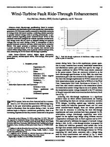
1. INTRODUCTION Among the wind turbine concepts, the doubly fed induction generator (DFIG) is a popular wind turbine system due to its high energy efficiency, reduced mechanical stress on the wind ____________________________________________________________________________________________ *Corresponding author: E-mail:
[email protected];
British Journal of Applied Science & Technology, 4(16): 2382-2394, 2014
turbine, separately controllable active and reactive power, and relatively low power rating of the connected converter [1], but due to the direct connection of the stator to the grid, the DFIG suffers from a great vulnerability to grid faults [2].Quite a few studies have been carried out to improve the LVRT capability of DFIG WT. Among the available approaches, protection devices such as crowbars are mostly used to bypass the rotor side converter once overloads are detected [3–5]. However, once the crowbar is enabled, the machine controllability will be lost and DFIG becomes a regular induction machine. In this case, instead of providing reactive power support to the grid, the generator absorbs large amounts of reactive power from the grid, which is not conducive to the grid recovery. There are other proposed solutions for fault ride through of DFIG using additional hardware like a series dynamic resistance in the rotor [6] and the stator [7], or using a series line side converter (LSC) topology as proposed in [8]. The use of a dynamic voltage restorer and superconducting fault-current limiter-magnetic energy storage system to enhance the LVRT capability of DFIG during grid faults were also investigated recently in [9-15]. In this paper the response of a WECS employing DFIG during 3 phase ground fault when applying a DVR and a STATCOM is investigated and results are compared. The comparison covers the stator and rotor voltage and current transients due to 3 phase ground faults. The response time to regain system stability is considered. A sudden drop in the grid voltage causes a large current to flow in the rotor, so comparing the ability of each device to limit this current is investigated. The affected system power factor, active and reactive power, and rotor speed are also investigated. The system is simulated using MATLAB software, and the results compared to conclude the better device for FRT.
2. MODELING OF DFIG SYSTEM WITH DYNAMIC VOLTAGE RESTORER (DVR) Fig. 1 shows the general configuration of the DFIG system, while Fig. 2 shows the single line diagram of DFIG with DVR. To eliminate the switching harmonics generated by the back-toback converter, a high frequency ac filter is connected to the stator side. The application of the DVR to enhance the FRT capability of the DFIG is investigated in which the DVR is a voltage-source converter (VSC) connected in series between the grid and the wind turbine generator. The DVR output voltage is added to the grid voltage instantaneously to achieve constant stator voltage under grid fault condition including balanced and unbalanced voltage dips. This device is able to eliminate the transient in the generator current and power at grid fault condition, hence the grid disturbances have no direct effect on the generator operation.
2.1 Voltage Sag Compensation The DVR, shown in Fig. 2, consists of an IGBT Voltage Source Inverter (VSI), an energy storage device, and low-pass passive filter connected in series with the distribution system via a transformer. PWM strategy is employed for triggering the IGBTs of VSI. Low-pass passive filters are used to convert the PWM inverted pulse waveform into a sinusoidal waveform by removing the higher order harmonic components generated from the DC to AC conversion in the VSI. The high voltage side of the injection transformer is connected in series with the distribution line, while the low voltage side is connected to the DVR power circuit. The basic function of the injection transformer is to adjust the voltage supplied by the filtered VSI output to the desired level while isolating the DVR circuit from the distribution network.
2383
British Journal of Applied Science & Technology, 4(16): 2382-2394, 2382 2014
Fig. 1. DFIG general configuration
2.2 DVR Control Strategy The aim of control technique of the DVR is to track the supply voltage and restore that to the pre-fault fault supply voltage during voltage sag or swell. Generally, voltage sags are associated with a phase angle jump in addition to the magnitude change. Thus, the control technique adopted should be capable of compensating for voltage magnitude, and phase shift. The adopted control scheme achieves the following functions: i.
Tracking the magnitude and phase angle of the supply voltage during normal operation to detect the occurrence of voltage sag or swell. This is achieved using software phase-locked locked loop (SPLL) technique. ii. Computation of the correcting voltage. iii. Generation of trigger pulses to the sinusoidal PWM based DC DC–AC AC inverter. iv. Termination of the trigger pulses after voltage sag is fixed
The reference of the compensation voltage across the transformer to be injected by DVR can be expressed as follows:
(1) where Vga,presag Vgb,presag, and Vgc,presag are the voltages across the low-voltage voltage side of the transformer before the voltage sag occurs, and Vga , Vgb , and Vgc are those after the voltage
2384
British Journal of Applied Science & Technology, 4(16): 2382-2394, 2014
sag occurs in the power system. This reference generation method is called a phaseinvariant injection, and it is a very effective method for the DFIG since the DFIG is so sensitive to the phase jump of the grid voltage.
Fig. 2. Single line diagram of DVR
3. MODELING OF DFIG SYSTEM WITH STATCOM STATCOM is a shunt-connected reactive power compensation device that is capable of generating or absorbing reactive power. The STATCOM has three main components: voltage source converter (VSC), coupling transformer and the control circuit. The VSC is modeled as a six-pulse PWM-IGBT converter with a DC-link capacitor. The interaction between the AC system voltage and the voltage at the STATCOM terminals controls the reactive power flow. If the system voltage is less than the voltage at the STATCOM terminals, the STATCOM acts as a capacitor and reactive power is injected from the STATCOM to the system. On the other hand, if the system voltage is higher than the voltage at the STATCOM terminal, the STATCOM behaves as an inductor and the reactive power transfers from the system to the STATCOM. Under normal operating conditions, both voltages are equal and there is no power exchange between the STATCOM and the AC system. Fig. 3 shows the STATCOM coupled with DFIG generation system. The active and the reactive power exchange between the STATCOM and the AC system is controlled via the VSC firing angle α and the modulation index m to maintain the voltage at the point of connection and the DC-voltage within permissible limits. The differential equations for Fig. 3 in three-phase form can be written as:
(2)
2385
British Journal of Applied Science & Technology, 4(16): 2382-2394, 2014
Fig. 3. Single line diagram of DFIG generation system with STATCOM where ia,ib,ic are the AC line currents of the STATCOM; Va,Vb and Vc are the PCC voltages; va1, vb1and vc1 are the inverter terminal voltages; R and L represent the equivalent conduction losses and the inductance for the transformer and the filter. By considering the system parameters and the system voltages as a three-phase balanced system, the threephase voltages and currents can be converted into a synchronously rotating d-q frame. Equation (2) can be represented in the d-q frame as following:
(3) where ω is the synchronous angular speed of the fundamental system voltage. Neglecting the voltage harmonics produced by the inverter, and according to the PWM technique, the voltage at the inverter output terminals and the DC-side can be written as:
where K is the inverter constant, which can be determined by the inverter structure, m is the modulation index of the PWM, Vdc is the DC-voltage across the STATCOM capacitor, and α
2386
British Journal of Applied Science & Technology, 4(16): 2382-2394, 2014
is the firing angle that controls the power flow between the STATCOM and the PCC. m and α are the PWM control variables which given by:
(5) The instantaneous active and reactive power injected or absorbed at the PCC can be written as:
(6) while the instantaneous active power at the DC-side can be expressed as:
(7) The system model given by the above equations, is used along with the PI controller to regulate the PCC and the DC-capacitor voltages.
4. SIMULATION RESULTS AND DISCUSSION The performance of the two systems; that with DVR and that with STATCOM, during 3phase fault occurring from t=0.2 till t= 0.3 are investigated, and results compared. Fig. 4a and 4b show the stator active and reactive power for the system employing the DVR and the system employing the STATCOM respectively. The smoother power profile for STATCOM is obvious, which proves the better system performance and lower transients. It is noticed that the series inductance of the DVR transformer prevents the power from reaching zero during the ground fault. Fig. 5a and 5b show the stator current for the system employing the DVR and the system employing the STATCOM respectively. The current peaks are higher for DVR system within the whole fault presence time. This proves that the STATCOM helps in mitigating the transients which protects the generator from overheating. Fig. 6a and 6b show the rotor current for the system employing the DVR and the system employing the STATCOM respectively. The current peaks are higher for DVR system as the fault starts and after it terminates. This proves that the STATCOM helps in mitigating the transients which protects the rotor converters from overheating.
2387
British Journal of Applied Science & Technology, 4(16): 2382-2394, 2014
4
4
x 10
3
Stator P &Q
2
1
0
-1
-2
-3
0
0.1
0.2
0.3
0.4
0.5
0.6
0.7
Time
Fig. 4a. P and Q with DVR 4
2.5
x 10
2 1.5
stator P& Q
1 0.5 0 -0.5 -1 -1.5 -2 -2.5
0
0.1
0.2
0.3
0.4
0.5
0.6
0.7
Time
Fig. 4b. P and Q with STATCOM
2388
British Journal of Applied Science & Technology, 4(16): 2382-2394, 2014
80 60
Stator current
40 20 0 -20 -40 -60 -80
0
0.1
0.2
0.3
0.4
0.5
0.6
0.7
0.4
0.5
0.6
0.7
Time
80
60
S tator current
40
20
0
-20
-40
-60
0
0.1
0.2
0.3 Time
Fig. 5a and b. Stator Currents 2389
British Journal of Applied Science & Technology, 4(16): 2382-2394, 2014
80 60 40
Rotor current
20 0 -20 -40 -60 -80
0
0.1
0.2
0.3
0.4
0.5
0.6
0.7
0.4
0.5
0.6
0.7
Time 60
40
Rotor current
20
0
-20
-40
-60
0
0.1
0.2
0.3 Time
Fig. 6a and b. Rotor currents Fig. 7a and 7b show the stator voltage for the system employing the DVR and the system employing the STATCOM respectively. The voltage reaches zero during the fault with the STATCOM device, while the series transformer inductance keeps an appreciable voltage magnitude during the fault with the DVR device. This result is in favor with DVR acting as protection for stator windings. However, this inductance increases the stator voltage to very high magnitudes which may damage the windings. This result is renders the STATCOM as better protection device.
2390
British Journal of Applied Science & Technology, 4(16): 2382-2394, 2014
Fig. 8a and 8b show the rotor voltage for the system employing the DVR and the system employing the STATCOM respectively. The two systems' responses are nearly the same due to isolation of rotor circuit from the applied FACTS devices. However, harmonics are higher in the system with DVR. Lower harmonics in the system with STATCOM means better power quality. 3000
2000
Stator voltage
1000
0
-1000
-2000
-3000
0
0.1
0.2
0.3
0.4
0.5
0.6
0.7
Time
Fig. 7a. Stator voltage with DVR 1000
S tator v oltage
500
0
-500
-1000
-1500
0
0.1
0.2
0.3
0.4
0.5
0.6
0.7
Time
Fig. 7b. Stator voltage with STATCOM
2391
British Journal of Applied Science & Technology, 4(16): 2382-2394, 2014
50 40 30
Rotor v oltage
20 10 0 -10 -20 -30 -40 -50
0
0.1
0.2
0.3
0.4
0.5
0.6
0.7
Time
Fig. 8a. Rotor voltage with DVR 80 60
Rotor v oltage
40 20 0 -20 -40 -60 -80
0
0.1
0.2
0.3
0.4
0.5
0.6
0.7
Time
Fig. 8b. Rotor voltage with STATCOM
2392
British Journal of Applied Science & Technology, 4(16): 2382-2394, 2014
5. CONCLUSION The fault ride through (FRT) capability of a doubly fed induction generator (DFIG) applied in wind energy conversion systems (WECS) is enhanced by applying DVR and STATCOM. PI controllers are tuned for MPPT and voltage adjustments. A comparison is done between the voltages, currents, active power, and reactive power for the generation system with DVR and that with STATCOM when a 3-phase ground fault occurs. The simulation results reveal the lower transients, lower system harmonics, and smoother power profiles for the system employing the STATCOM. The only merit for DVR application is the non-zero stator voltage, which provides protection for stator windings.
COMPETING INTERESTS Authors have declared that no competing interests exist.
REFERENCES 1. 2. 3.
4. 5. 6. 7. 8. 9.
10. 11.
12.
Thomas A. Wind power in power systems. Wiley: New York, NY, USA; 2005. Mohseni M, Islam S, Masoum M. Impacts of symmetrical and asymmetrical voltage sags on DFIG-based wind turbines considering phase angle jump. Voltage Recovery, and Sag Parameters; 2012. Zhang W, Zhou P, He Y. IEEE Trans. Power Electron. Analysis of the By-Pass Resistance of an Active Crowbar for Doubly-Fed Induction Generator Based Wind Turbines under Grid Faults. In Proceedings of International Conference on Electrical Machines and Systems (ICEMS 2008), Wuhan, China, 17–20 October 2008. 2011;26:1587–1598. Pannell G, Atkinson D, Zahawi B. Minimum-threshold crowbar for a fault-ride-through grid-code-compliant DFIG wind turbine. IEEE Trans. Energy Convers. 2010;25:750– 759. Morren J, De Haan S. Ride through of wind turbines with doubly fed induction generator during a voltage dip. IEEE Trans. Energy Convers. 2005;20:35–441. Yang J, Fletcher J, O’Reilly J. A series-dynamic-resistor-based converter protection scheme for doubly-fed induction generator during various fault conditions. IEEE Trans. Energy Conversion. 2010;25:422–432. Causebrook A, Atkinson D, Jack A. Fault ride-through of large wind farms using series dynamic braking resistors. IEEE Trans. Power Syst. 2007;22:966–975. Flannery P, Venkataramanan G. Unbalanced voltage sag ride through of a doubly fed induction generator wind turbine with series grid-side converter. IEEE Trans Ind Appl. 2009;45:1879–1887. Wessels C, Gebhardt F, Fuchs FW. Fault ride-through of a DFIG wind turbine using a dynamic voltage restorer during symmetrical and asymmetrical grid faults. IEEE Trans. Power Electron. 2011;26:807–815. Guo W, Xiao L, Dai S. Enhancing low-voltage ride-through capability and smoothing output power of DFIG with a superconducting fault-current limiter–magnetic energy storage system. IEEE Trans. Energy Convers. 2012;27:277–295. Xiang D, Ran L, Tavner PJ, Yang S. Control of a doubly fed induction generator in a wind turbine during grid fault ride-through. IEEE Trans. Energy Conversion. 2006;21:652–662. Xu L, Wang Y. Dynamic modeling and control of DFIG-based wind turbines under unbalanced network conditions. IEEE Trans. Power Syst. 2007;22:314–323.
2393
British Journal of Applied Science & Technology, 4(16): 2382-2394, 2014
13.
Xu L. Enhanced control and operation of DFIG-based wind farms during network unbalance. IEEE Trans. Energy Convers. 2008;23:1073–1081. 14. Hu J, He Y, Xu L, Williams BW. Improved control of DFIG systems during network unbalance using PI-R current regulators. IEEE Trans. Ind Electron. 2009;56:439–451. 15. Hu J, He Y. Reinforced control and operation of DFIG-based wind power-generation system under unbalanced grid voltage conditions. IEEE Trans. Energy Convers. 2009;24:905–915. _________________________________________________________________________ © 2014 Saleh et al.; This is an Open Access article distributed under the terms of the Creative Commons Attribution License (http://creativecommons.org/licenses/by/3.0), which permits unrestricted use, distribution, and reproduction in any medium, provided the original work is properly cited.
Peer-review history: The peer review history for this paper can be accessed here: http://www.sciencedomain.org/review-history.php?iid=492&id=5&aid=4319
2394