around the plant (as it is typical, for instance, in automotive applica- tions). We propose a ...... ing paradigm for programming safety-critical control applica- tions.
Fault-Tolerant Deployment of Embedded Software for Cost-Sensitive Real-Time Feedback-Control Applications
∗
Claudio Pinello Luca P. Carloni Alberto L. Sangiovanni-Vincentelli EECS Department, University of California at Berkeley, Berkeley, CA 94720-1772 {pinello,lcarloni,alberto}@eecs.berkeley.edu
Abstract Designing cost-sensitive real-time control systems for safetycritical applications requires a careful analysis of the cost/coverage trade-offs of fault-tolerant solutions. This further complicates the difficult task of deploying the embedded software that implements the control algorithms on the execution platform that is often distributed around the plant (as it is typical, for instance, in automotive applications). We propose a synthesis-based design methodology that relieves the designers from the burden of specifying detailed mechanisms for addressing platform faults, while involving them in the definition of the overall fault-tolerance strategy. Thus, they can focus on addressing plant faults within their control algorithms, selecting the best components for the execution platform, and defining an accurate fault model. Our approach is centered on a new model of computation, Fault Tolerant Data Flows (FTDF), that enables the integration of formal validation techniques.
1
Introduction
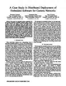
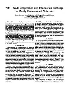
The increasing role of embedded software in real-time feedback-control systems drives the demand for fault-tolerant design methodologies [20]. The aerospace and automotive industries offer many examples of systems whose failure may have unacceptable costs (financial, human or both). In a realtime feedback-control system, like the one of Figure 1, the controller interacts with the plant by means of sensors and actuators. A controller is a hardware-software system where the software algorithms that implement the control law run on an execution platform. An execution platform is a distributed system that is typically made of a software layer (RTOS, middleware services, . . . ) and a hardware layer (a set of processing elements, called electronic control units or ECUs, connected via communication channels like buses, crossbars, or rings). The design of these heterogeneous reactive distributed systems is made even more challenging by the requirement of making them resilient to faults. Technically, a fault is the cause of an error, an error is the part of the system state which may cause a failure, and a failure is the deviation of the system from the specification [19]. A deviation from the specification may be due to designers’ mistakes (“bugs”) or to accidents occurring while the system is operating. We classify the latter in two categories that are relevant for feedback-control systems: plant faults and execution platform faults. Theoretically, all bugs can be eliminated before the system is deployed. In practice, they ∗ This research was supported in part by the Marco/Gigascale Systems Research Center, the NSF under the project ITR (CCR-0225610), and BMW.
are minimized by using design environments that are based on precise models of computation (MoC), whose well-defined semantics enable formal validation techniques [3, 9, 10], (e.g., synchronous languages [7]). Instead, plant faults and platform faults must be dealt with on-line. Hence, they must be included in the specification of the system to be designed. Plant faults, including sensors and actuators, must be handled at the algorithmic level using estimation techniques and adaptive control methods. For instance, a drive-by-wire system might need to handle properly a tire puncture or the loss of one of the four brakes. Faults in the execution platform affect the computation, storage, and communication elements. For instance, a loss of power may turn off an ECU, momentarily or forever. System operation can be preserved in spite of platform faults if alternative resources supplying the essential functionality of the faulty one are available. Hence, the process of making the platform fault-tolerant usually involves the introduction of redundancy with obvious impact on the final cost. While the replication of a bus or the choice of a faster microprocessor may not affect sensibly the overall cost of a new airplane, their impact is quite significant for high-volume products like the ones of the automotive industry. The analysis of the trade-offs between higher redundancy and lower costs is a challenging HW-SW codesign task that designers of faulttolerant systems for cost-sensitive applications must face in addition to the following two: (1) how to introduce redundancy, and (2) how to deploy the redundant design on a distributed execution platform. Since these two activities are both tedious and error prone, designers often rely on off-the-shelf solutions to address fault tolerance, like Kopetz’s Time Triggered Architecture (TTA) [16]. One of the main advantages of off-the-shelf solutions is that the application does not need to be aware of the fault tolerant mechanisms that are transparently provided by the architecture to cover the execution platform faults. Instead, designers may focus their attention on avoiding design bugs and tuning the control algorithms to address the plant faults. However, the rigidity of off-the-shelf solutions may lead to suboptimal results from a design cost viewpoint. These considerations motivate the present work. We propose an interactive design methodology that involves designers in the exploration of the redundancy/cost trade-off. To do so efficiently, we introduce automatic synthesis techniques that process simultaneously the algorithm specification, the characteristics of the chosen execution platform, and the corresponding fault model. In particular, the designers focus on the control algorithms and the selection of the components and architecture
actuator
sensor
plant
actuator
actuator driver
inverted pendulum (the plant)
sensor
control law algorithms
sensor driver
sensor
m
sensor
m
sensor driver
actuator driver
embedded software RTOS & middleware
sensor
hardware architecture ECU ECU
ECU ECU
ECU ECU
ECU ECU
m
input
m
coarse control task
m
fine control task
m
m
arbiter
m
actuator
output
m
actuator
execution platform
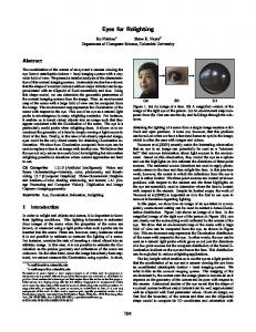
Figure 3. Controlling an inverted pendulum.
controller
Figure 1. A real-time control system.
ECU0
ECU1
ECU2
CH0 CH1
Figure 2. A simple platform graph. for the execution platform. In addition, they also specify the relative criticality of each algorithm process and the expected set of platform faults. Then, we use this information to (1) automatically deduce the necessary software process replication, (2) distribute each process on the execution platform, and (3) derive an optimal scheduling of the processes on each ECU to satisfy the overall timing constraints. Together, the three steps (replication, mapping, and scheduling) result in the automatic deployment of the embedded software on the distributed execution platform. When the final results do not satisfy the timing constraints for the control application, precise guidelines are returned to the designers who may use them to refine the control algorithms, modify the execution platform, and revisit the fault model. While being centered on a synthesis step, our approach does not exclude the use of pre-designed components, such as TTA modules, communication protocols like TTP, or fault-tolerant operating systems. These components can be part of a library of building blocks that the designer may use to further explore the fault-coverage/cost trade-off. Finally, the proposed methodology is founded on a new MoC, fault tolerant data flow (FTDF), thus making it amenable to the integration of formal validation techniques.
2
The Proposed Design Methodology
The Fault Model. For the sake of simplicity, in most of this paper we assume fail silence: components either provide correct results or do not provide any result at all. Recent work shows that fail-silent platforms can be realized with limited area overhead and virtually no performance penalty [5]. The fail silence assumption can be relaxed if invalid results are detected otherwise, as in the case of CRC-protected communication and voted computation [12]. Also, the presence of value
errors, where majority voting is needed, can be accounted for in the FTDF communication media (see Section 3). The same is true for Byzantine failures, where components can have any behavior, including malicious ones like coordinating to bring the system down to a failure [18]. In addition to the type of faults, a fault model also specifies the number (or even the mix) of faults to be tolerated [23]. A statistical analysis of the various components MTBFs (mean time between faults), their interactions and MTBR (mean time between repairs), should determine which subsystems have a compound MTBF that is so short to be of concern. The use of failure patterns to capture effectively these interactions was proposed in [8], which is the basis of our approach. Setup. Consider the feedback control system in Figure 1. The control system repeats the following sequence at each period Tmax : (1) sensors are sampled, (2) software routines are executed, and (3) actuators are updated with the newly-processed data. The actuator updates are applied to the plant at the end of the period to help minimize jitter, a well known technique in the real-time control community [24, 15]. In order to guarantee correct operation, the worst-case execution time (WCET) among all possible iterations must be smaller than the given period Tmax (our real-time constraint), which is determined by the designers of the controller based on the characteristics of the application. Moreover, the critical subset of the control algorithms must be executed in spite of the specified platform faults. We use software replication to achieve fault tolerance: critical routines are replicated statically (at compile time) and executed on separate ECUs and the processed data are routed on multiple communication paths to withstand channel failures. Example. Figure 3 illustrates a FTDF graph for a paradigmatic feedback-control application, the inverted pendulum control system. The controller is described as a bipartite directed graph G where the vertices, called actors and communication media, represent software processes and data communication. Figure 2 illustrates a possible platform graph PG, where vertices represent ECUs and communication channels and edges describe their interconnections. The Core Idea. A failure pattern is a subset of vertices of PG that may fail together during the same iteration. A set of failure patterns identify the fault scenarios to be tolerated. The following relations are the basis to derive a fault-tolerant deployment of G on PG: • fault-tolerance binding: for each failure pattern the execution of a corresponding subset of the actors of G must
Sens
Coarse CTRL
Sens
Input Fine CTRL
Sens
Arbiter Best
Act Output
FaultBehavior, Constraints
ECU0
ECU1
ECU2
Act CH0 CH1
Parse
ECU0
CH0
ECU1
Sens
Sens
Act Act Act
Input
Fine CTRL Fine CTRL Fine CTRL
Act
Coarse CTRL
Arbiter Best
Output
Input
Fine CTRL
Arbiter Best
Output
Schedule
CoarseCTRL
Input
CoarseCTRL
FineCTRL
CH0
ECU1 Sens
Act
Arbiter Output BestArbiter Output BestArbiter Output Best
Input
ECU2 Sens ECU2 Sens ECU2 Sens
Coarse CTRL
ECU0 Sens
Coarse Input CTRL Coarse Input CTRL Coarse Input CTRL
Act
Sens
ECU1 Sens ECU1 Sens ECU1 Sens CH1 CH1 CH1
Act
CH1
Merge
SynDEx Non-FT Mapping Non-FT Mapping Non-FT Mapping
ECU2
ECU0 Sens ECU0 Sens ECU0 Sens CH0 CH0 CH0
CH1
ArbiterBest
Act
ArbiterBest
ECU2 Sens
Output
Output Act
Act
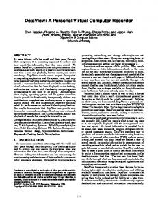
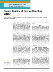
Figure 4. Proposed Design Flow.
be guaranteed. This subset is identified a-priori based on the relative criticality assignment. • functional binding: a set of mapping constraints and performance estimates indicate where on PG each vertex of G may be mapped and the corresponding WCET, see [11]. Design Flow. Figure 4 illustrates the proposed interactive design flow where designers • specify the controller (the top-left FTDF graph); • assemble the execution platform (the top-right PG); • specify a set of failure patterns (subsets of PG); • specify the fault tolerance binding (fault behavior); • specify the functional binding. A synthesis tool automatically • introduces redundancy in the FTDF graph; • maps actors and their replicas onto PG; • schedules their execution. Finally, a verification tool checks whether the fault-tolerant behavior and the timing constraints are met1 . If no solution is found, the tool returns a violation witness that can be used to revisit the specification and to provide hints to the synthesis tool.
3
Fault Tolerant Data Flows
In this section we present the structure and general semantics of the FTDF MoC. The basic building blocks are actors and communication media. FTDF actors exchange data tokens at each iteration with synchronous semantics [7]. An actor belongs to one of six possible classes: sensors, actuators, inputs, outputs, tasks, arbiters. Sensor and actuator actors read and update respectively the sensor and actuator devices interacting with the plant. Input actors perform sensor fusion, output actors are used to balance the load on the actuators, while task actors are responsible for the computation workload. Arbiter actors mix the values that come from actors with different criticality to reach to the same output actor (e.g. braking command and anti-lock braking system (ABS) 2 ). 1 Joint
work with Sam Williams, UC Berkeley advocate running non-safety critical tasks, e.g. door controllers, on separate HW. However some performance enhancement tasks, e.g. side-wind compensation, may share sensors and actuators with critical tasks (steer-bywire). It may be profitable to have them share the execution platform as well. 2 We
Finally, state memories are connected to actors and operate as one-iteration delays. With a slight abuse of terminology the terms state memory and memory actor are used interchangeably in this paper. Tokens. Each token consists of two fields: Data, the actual data being communicated; Valid, a boolean flag indicating the outcome of fault detection on this token. When Valid is “false” either no data is available for this iteration, or the available data is not correct. In both cases the Data field should be ignored. The Valid flag is just an abstraction of more concrete and robust fault detection implementations. Communication Media. Communication occurs via unidirectional (possibly many-to-many) communication media. All replicas of the same source actor write to the same medium, and all destination actors read from it. Media act both as mergers and as repeaters sending the single “merged” result to all destinations. More formally, the medium provides the correct merged result or an invalid token if no correct result is determined. Assuming fail-silence, merging amounts to selecting any of the valid results; assuming value errors majority voting is necessary; assuming Byzantine faults we need rounds of voting (see the consensus problem [6]). Communication media must be distributed to withstand platform faults, typically this means having a repeater on each source ECU and a merger on each destination ECU (using broadcasting communication channels helps reduce message traffic greatly). Using communication media, actors always receive exactly one token per input and the application behavior is independent of the type of platform faults. The transmission of tokens is initiated by the active elements: regular actors and memory actors. Regular Actors. When an actor fires, its sequential code is executed. This code is: stateless (state must be stored in memory actors), deterministic (identical inputs generates identical outputs), non-blocking (once fired, it does not await for further tokens, data, or signals from other actors) and terminating (bounded WCET). The firing rule specifies which subsets of input tokens must be valid to fire the actor, typically all of them (and firing rule). However, the designer may need to specify partial firing rules for input and arbiter actors. For example, an input actor reading data from three sensors may produce a valid result even when one of the sensors cannot deliver data (e.g. when the ECU where the sensor is mapped is faulty). Memory Actors (State Memories). A memory provides its state at the beginning of an iteration and has a source actor, possibly replicated, that updates its state at every iteration. State memories are analogous to latches in a sequential digital circuit: they store the results produced during the current iteration for use in the next one.
3.1 Actor Compositions The following rules specify the set of valid actor compositions to obtain a legal FTDF graph. Some basic rules (e.g. all input and output ports of an actor should be connected, datatypes should be matched, etc.) are common to most dataflow models and are assumed implicitly here.
Definition 3.1.1 Given a set of actors A and communication media M, a FTDF graph G is a pair (V, E) where V = A ∪ M is the set of vertices and E ⊂ (A × M) ∪ (M × A) is the set of directed edges. Note that G is bipartite and active elements are always connected via a communication medium (see Figure 3). We assume the partition A = AS ∪ AAct ∪ AI ∪ AO ∪ AT ∪ AA ∪ AM of actors in the six regular actor types and the memory actors. Definition 3.1.2 Given a FTDF graph G , and a vertex v ∈ V , the successor neighbors of v are denoted by neig+ (v) = {w ∈ V s.t. (v, w) ∈ E}, the predecessor neighbors by neig− (v) = {w ∈ V s.t. (w, v) ∈ E} and all the neighbors neig(v) are the union of the two. Definition 3.1.3 Given a FTDF graph G , and an actor v ∈ A, the successor actors of v are denoted by succ(v) = neig+ (neig+ (v)), and the predecessor actors by pred(v) = neig− (neig− (v)), Definition 3.1.4 A FTDF graph G is “legal” if • G contains no causality cycles i.e. if graph G 0 = (V 0 , E 0 ) where V 0 = V \ AM , E 0 = E ∩ (V 0 ×V 0 ) is acyclic • ∀v ∈ AI , pred(v) ⊂ AS ∪ AM and ∀v ∈ AS , succ(v) ⊂ AI • ∀v ∈ AAct , pred(v) ⊂ AO and ∀v ∈ AO , succ(v) ⊂ AAct ∪ AM • ∀v ∈ AS , neig−(v) = 0/ and ∀v ∈ AAct , neig + (v) = 0/ Finally FTDF graphs can express redundancy, i.e. one or more actors may be replicated. All the replicas of an actor v ∈ A are denoted by R (v) ⊂ A. Note that any two actors in R (v) are of the same type and must compute the same function. This basic condition is motivated in Section 4.2 where replica determinism is discussed.
4
Replication, Mapping, and Scheduling
Designers must provide the system specification tuple (G , Tmax , PG, F, χ, ψ, µ, τ), i.e.: • FTDF graph G and its iteration period Tmax ; • platform graph PG = (P,C, D), where P is the set of ECUs, C is the set of channels, and D ⊂ P ×C is the set of edges connecting them. • set of failure patterns F ⊂ 2P∪C , including the empty fail/ f1 , . . . , fk }. ure pattern, i.e. F = {0, • the fault behavior, i.e. a criticality assignment for actors and failure patterns: χ : A → IN, ψ : F → IN. For any fault of a failure pattern f i ∈ F, at least one replica of each actor a such that χ(a) ≥ ψ( f i ) must be executed. • mapping constraints µ : V → 2P∪C , i.e. on which vertices of PG can a given vertex of G be mapped.3 • performance annotations, i.e. WCET of actors on ECUs and worst case transmission time (WCTT) of data on channels τ : V × P ∪ C → IN, with the convention that τ(v, r) = 0 ∀v ∈ M, ∀r ∈ P. 3 Some actors may require special resources not available at all ECUs. The most notable examples are the sensor and actuator actors that clearly need direct access to the I/O resources. Other examples are floating point unit, size of the stack/RAM memories for temporary data, etc.
All this information contributes to specifying what the system should do and drive how it should be implemented. The replication of sensors and actuators is not performed automatically because they may have a major impact on cost. For consistency, their criticality is always set to the minimum, i.e. ∀s ∈ AS ∪ AAct , χ(s) = 0. To guarantee execution of G in ab/ = 0. sence of faults it is recommended that ψ(0)
4.1 Mapping and scheduling a graph G on PG A mapping of G on PG is a directed graph L = (LV , LE ) where vertices in LV are elements of (P ∪ C) × V . A vertex l ∈ LV with l = (r, v) means that actor or medium v is mapped to resource r. An edge e ∈ LE with e = (l1 , l2 ), l1 = (r1 , v1 ) and l2 = (r2 , v2 ), models data transfer from l1 to l2 . Mappings must satisfy edge consistency: edge e ∈ LE connects vertices l1 = (r1 , v1 ) and l2 = (r2 , v2 ) only if the associated FTDF elements depend on one another (i.e. (v1 ∈ A ∧ v2 ∈ succ(v1 )) ∨ (v1 , v2 ) ∈ E) and the associated resources r1 , r2 are adjacent vertices in PG (i.e. (r1 = r2 ∈ P) ∨ (r1 , r2 ) ∈ D ∨ (r2 , r1 ) ∈ D). Since L preserves the dependencies in G , it contains no causality cycles. So, if we neglect memory actors, L defines a partial order. For a given v ∈ V , the set `(v) = {r ∈ P ∪C, s.t. (r, v) ∈ LV } denotes the set of vertices of L where v is mapped. Like in [8], we define a schedule S as a pair of functions ( f (·), h(·)) with f : P → A∗ and h : C → M ∗ where A∗ and M ∗ are the sets of sequences over A and M. For each ECU p ∈ P, f (p) denotes the sequence of actors that must be executed on p, thereby defining a total order on actors mapped on p. Similarly ∀c ∈ C, h(c) defines a total order on data communication mapped on channel c. A pair (L , S ) is called a deployment. To avoid deadlocks, the total orders defined by S must be compatible with the partial order in L . To avoid causality problems, memory actors are scheduled before any other actor, thus using the results of the previous iteration. Schedules based on total orders are called static: there are no run-time decisions to make, each ECU and each channel controller simply follows the schedule. However, in the context of a faulty execution platform an actor may not receive enough valid inputs to fire and this may lead to starvation. Like in [8], we solve this problem by skipping an actor if it cannot fire and by skipping a communication if no data is available.
4.2 Replica determinism Given a mapping L , we want to preserve replica determinism: if two actors in R (v) fire, they produce identical results. For general MoCs the order of arrival of results must also be the same for all replicas. Synchrony of FTDF makes this check unnecessary. Clearly a synchronization algorithm must be implemented in the execution platform, see in example [17]. Replica determinism in FTDF can be achieved enforcing two conditions: (1) all actors in R (v) compute the same function, and (2) for any failure pattern, if two replicas get a firing subset of inputs they get the same subset of inputs. Condition (1) is enforced by construction by allowing only identical replicas. Condition (2) amounts to a consensus problem and it can either be checked at run-time (like for Byzantine agreement rounds of voting), or it can be analyzed statically at
0
compile time (if the fault model is milder). Our interest in detectably faulty execution platforms makes the latter approach appear more promising and economical. Condition (2) is trivially true for all actors with the “and firing rule”. For input and arbiter actors the condition must be checked and enforced. We derive procedure extend(L ) that transforms a mapping L to enforce condition (2). Its basic step is the following: if a failure pattern may lead to two different firing sets for two replicas, extend the mapping with routings of the results to the replica that lacks them. If there is enough connectivity in PG, repeating this step will eventually stabilize the mapping and achieve replica determinism. Memory actors invalidate their state after transmitting it at the beginning of an iteration and before other actors may fire. Hence, they can be treated as stateless. Further, condition (2) is trivially true for them because they have a single input.
200
400
600
800
1000
r SystemC/tempsens_medium[0]
C0 C1
C2
r SystemC/tempsens_medium[1]
r SystemC/tempsens_medium[2]
r SystemC/actorout
r SystemC/coarseout
r SystemC/finecontroller.out_0
r SystemC/fineout
r SystemC/SelectOut
r SystemC/torque_actuator[0].out_0
r SystemC/torque_actuator[1].out_0
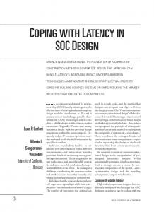
Figure 5. Closed loop behavior of the pendulum controller, sudden “0-flat” lines indicate injected faults.
4.3 Synthesis Given the system specification, a synthesis algorithm should derive a fault tolerant deployment (i.e. a redundant mapping LFT and its associated schedule SFT ). First consider the following auxiliary mapping problem Problem 1 Given G , PG, and a set of constraints µ0 , find an edge-consistent mapping L 0 = (LV0 , L0E ), such that: • ∀v ∈ A, (`(v) = {p}) ∧ p ∈ µ0 (v) • ∀v ∈ M, `(v) ⊂ µ0 (v) A solution to Problem 1 is a non-fault-tolerant mapping. The following synthesis algorithm uses the solutions to a number of instances of Problem 1 to derive a fault-tolerant deployment (LFT , SFT ). Algorithm 1 Consider the tuple (G , Tmax , PG, F, χ, ψ, µ, τ) 1. let L0/ be the solution to Problem 1 using µ0 ≡ µ / do 2. for each f i ∈ F \ {0} (a) build a set of constraints µ fi such that � i f v ∈ A ∧ χ(v) < ψ( f i ) `0/ (v), µ fi (v) = µ(v) \ fi , otherwise (b) let L fi be the solution to Problem 1 using µ0 ≡ µ fi 3. merge the resulting L0/ , L f1 , . . . , L fk into a redundant map0 =S ping LFT f i ∈F L f i = (LVF T , LEFT ) 0 ) 4. enforce replica determinism: LFT = extend(LFT 5. derive a schedule SFT for the execution of LFT In step 3 the redundant mapping is simply given by: S S LV0 FT = fi ∈F LV fi , L0EFT = fi ∈F LE fi . The resulting fault tolerant deployment (LFT , SFT ) is guaranteed by construction to meet the fault behavior (χ(·), ψ(·)). The schedule SFT can be derived using a list scheduling algorithm driven by any heuristic cost function [25]. Heuristics minimizing the worst case iteration time are excellent candidates. The algorithm terminates successfully if the timing constraint Tmax is satisfied for each failure pattern in F. It may terminate earlier if the solution to one of the auxiliary problems in step 2b cannot be found or if extend(·) fails.
5
Design Environment
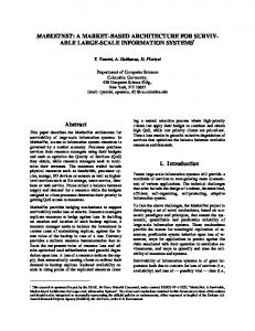
We embedded the tools that support the design flow in the M ETROPOLIS [4] design environment. Using its modeling language, Metropolis Meta Model, designers can specify, analyze, and synthesize systems at several levels of abstraction, from purely functional description (with heterogeneous MoCs) to mapped behavior on an micro-architecture. We developed a library for the specification of FTDF graphs [21] that makes possible to simulate the closed loop system, perform fault injection simulations, and generate waveforms like in Figure 5. The synchronous and periodic semantics of FTDF makes understanding and analyzing the behavior of the distributed system quite easy. The rest of the toolkit consists of an implementation in C of Algorithm 1 that uses S YN DE X to solve the auxiliary Problems 1 in the inner step. While it does not deal with fault tolerance 4 , S YN DE X effectively schedules homogeneous synchronous data flows on a distributed platform, given a set of mapping constraints and WCET/WCTT [1]. Further, as it solves the mapping problem, S YN DE X tries also to minimize the worst case iteration time by efficiently parallelizing the execution of actors on the distributed platform. These wellparallelized mappings are merged into LFT , which inherits the parallelism, thus making it easier to derive a schedule SFT with a small worst case iteration time. We tested our design flow on the simple drive-by-wire model of Figure 6, developed at the BMW Technology Office in Palo Alto. Interactivity. Designers can either provide a loose specification and let the tool derive a solution, or specify a partially replicated and mapped design to be completed by the tool. If they provide a FTDF G where some actors are already replicated, the tool will only replicate the remaining ones, by simply modifying step 2a so that all replicated actors can only be mapped as in L0/ from step 1. By using mapping constraints and adding dummy data dependencies, designers can guide the construction of a deployment to any desired degree (including a single solution of their choosing). The designer’s guidance can compensate for cases where the mapping and scheduling heuristics yield poor results. Designers can also easily modify 4 In [13] the authors implemented an efficient scheduling heuristic within S YN DE X to tolerate ECU failures but not channel failures.
SynDExV5 application: /vol/hyper/hyper2/pinello/syndex51/boom/newdbwex3/newdbwex3
References
!o0 ?i1 C0FUNComputeBrakeCommandch1 !o1
?i0 !o0 ?i1 !o1 ?i2 C0AR1Mixer_Brakech1 ?i3 !o2 ?i4 !o3 ?i5
?i0 ?i1 ?i2C0IN1DiagnosisBrakePedalch1!o0 ?i3 ?i4 !DigitalOut C1SENAcqSig_109_pedal !Digitalpip !DigitalOut C1SENAcqSig_110_pedal !DigitalOut C1SENAcqSig_111_pedal !DigitalOut C1SENAcqSig_112_pedal !DigitalOut C1SENAcqSig_113_handBR !DigitalOut C1SENAcqSig_114_clampforce !DigitalOut C1SENAcqSig_115_clampforce !DigitalOut C1SENAcqSig_116_clampforce !DigitalOut C1SENAcqSig_117_clampforce
!DigitalOut C1SENAcqSig_264_speed !DigitalOut C1SENAcqSig_265_speed !DigitalOut C1SENAcqSig_266_speed !DigitalOut C1SENAcqSig_267_speed
?i0 C1ACTManip_Brake_fl ?i0 C1ACTManip_Brake_fr
?i0 ?i1
!o0
?i0 C1ACTManip_Brake_rl
?i4
!o3
?i0 C1ACTManip_Brake_rr
!o1 ?i2 C1FUNComp_Cmd_ABS_Brch1 !o2 ?i3
?force_clp_fl_base_des !BrakeForceOutFL ?force_clp_fr_base_des ?force_clp_rl_base_des !BrakeForceOutFR ?force_clp_rr_base_des C0AR1Arb_Br_ch1 ?Master_BrakeForceFL !BrakeForceOutRL ?Master_BrakeForceFR ?Master_BrakeForceRL !BrakeForceOutRR ?Master_BrakeForceRR
?force_clp_fl_base_des !BrakeForceOutFL ?force_clp_fr_base_des !BrakeForceOutFR C0OU3_Br_ch1 ?force_clp_rl_base_des !BrakeForceOutRL ?force_clp_rr_base_des !BrakeForceOutRR
?RackPosition1Fil ?RackPosition2Fil ?RackPosition3Fil !VotedRackPosition ?RackPosition4Fil C0IN1Diagnosis_Lateral_Sens ?StirWheelAngle1Fil ?StirWheelAngle2Fil !VotedStirWheelAngle ?StirWheelAngle3Fil ?StirWheelAngle4Fil
?StirBaseIn C0AR1Arb_Stir_ch1!StirOut1 ?Master_StirIn !StirOut2
?StirBaseIn C0OU1_Stir_ch1!StirOut1 ?Master_StirIn !StirOut2
!DigitalOut C1SENAcqSig_105_angle !DigitalOut C1SENAcqSig_106_angle !DigitalOut C1SENAcqSig_107_angle !DigitalOut C1SENAcqSig_108_angle
!DigitalOut C1SENAcqSig_161_rack !DigitalOut C1SENAcqSig_162_rack
?TieRodForce1Fil ?StirWheelTorque3Fil !VotedStirWheelTorque ?StirWheelTorque2Fil ?TieRodForce3Fil C0IN1Diagnosis_Feedback_Sens !VotedFieRodForce ?StirWheelTorque1Fil ?TieRodForce2Fil
?i0 C1ACTManip_HandW1 ?i0 C1ACTManip_HandW2
?InStirWheelTorque !Out ?InTieRodForceC0FUNComputeStirTorqueComm !DigitalOut C1SENAcqSig_227_rod !DigitalOut C1SENAcqSig_228_rod !DigitalOut C1SENAcqSig_229_rod
!DigitalOut C1SENAcqSig_224_torque !DigitalOut C1SENAcqSig_225_torque !DigitalOut C1SENAcqSig_226_torque !DigitalOut C1SENAcqSig_262_latacc !DigitalOut C1SENAcqSig_263_yaw
?RackPosition1Fil ?RackPosition2Fil ?RackPosition3Fil ?RackPosition4Fil !BrakeActuatorFL ?TieRodForce1Fil ?TieRodForce2Fil ?TieRodForce3Fil ?PedalSensor1Fil !BrakeActuatorFR ?PedalSensor2Fil ?PedalSensor3Fil ?ClampForceFLFil ?ClampForceFRFil ?ClampForceRLFil !BrakeActuatorRL ?ClampForceRRFil ?SpeedFLFil C1FUNM_Ctrl_ch1 ?SpeedFRFil ?SpeedRLFil !BrakeActuatorRR ?SpeedRRFil ?StirWheelAngle1Fil ?StirWheelAngle2Fil ?StirWheelAngle3Fil ?StirWheelAngle4Fil !HandWheelTorqueActuator ?HandBrakeSwitchFil ?BrakeSwitchFil ?YawRateFil ?LateralAccelerationFil !StirActuator ?StirWheelTorque1Fil ?StirWheelTorque2Fil ?StirWheelTorque3Fil
[2] K. Ahn, J. Kim, and S. Hong. Fault-tolerant real-time scheduling using passive replicas. In Proc. Pacific Rim Int.nal Symp. on Fault-Tolerant Systems, Taipei, Taiwan, 1997.
?i0 C1ACTManip_Steer1 ?i0 C1ACTManip_Steer2
?InStirAngleC0FUNComputeStirCommand_ch1 !Out ?InRackPosition
!DigitalOut C1SENAcqSig_159_rack !DigitalOut C1SENAcqSig_160_rack
[1] SynDEx webpage. http://www-rocq.inria.fr/syndex/.
?BaseTorque !TorqueOut1 C0AR1Arb_Handwheel_ch1 ?Master_Torque !TorqueOut2
L0
ECU3 L1 L2
L0
?BaseTorque !TorqueOut1 C0OU1_Handwheel_ch1 ?Master_Torque !TorqueOut2
L0
ECU2 L1 L2
ECU5 L1 L2
L0
ECU4 L1 L2
L0 root L1 L2 L0
L0
ECU0 L1 L2
ECU1 L1 L2
channel1 o channel2 o channel3 o
[3] R. Alur, T. Dang, J. Esposito, Y. Hur, F. Ivancic, V. Kumar, I. Lee, P. Mishra, G. J. Pappas, and O. Sokolsky. Hierarchical Modeling and Analysis of Embedded Systems. Proc. of the IEEE, 91(1):11–28, January 2003. [4] F. Balarin, L. Lavagno, C. Passerone, A. Sangiovanni-Vincentelli, M. Sgroi, and Y. Watanabe. Modeling and designing heterogeneous systems. Technical Report 2001/01 Cadence Berkeley Laboratories, November 2001. [5] M. Baleani, A. Ferrari, L. Mangeruca, A. Sangiovanni-Vincentelli, M. Peri, and S. Pezzini. Fault-tolerant platforms for automotive safety-critical applications. In Proc. of the Intl. Conf. on Compilers, Architectures and Synthesis for Embedded Systems, pages 170–177. ACM Press, 2003. [6] M. Barborak, M. Malek, and A. Dahbura. The consensus problem in fault-tolerant computing. ACM Computing Surveys, 25(2):171–220, June 1993.
Figure 6. Drive-By-Wire example in SynDEx, platform graph is at the bottom-left corner.
the platform graph PG and τ to vary its performance, redundancy and ultimately its cost. Finally, various design alternatives can be evaluated fairly quickly thanks to the automatic synthesis algorithm.
6
Concluding Remarks
The proposed approach for the deployment of control algorithms on distributed fault-tolerant platforms enables designers to explore rapidly the design space. They can make informed decisions about changing/restructuring the algorithms, the execution platform, and the fault behavior. The approach is based on a model of computation (FTDF) that represents an interesting paradigm for programming safety-critical control applications. In particular, FTDF exposes task-level parallelism and formalizes tasks interaction, simplifying the analysis and distribution of the control programs. FTDF also deals with redundancy explicitly and is fault-model independent. An important extension of this MoC will be multi-rate FTDF, where actors execute at different rates (similarly to Signal’s MoC [14]). We are currently developing a run-time library in C to support FTDF semantics on a network of Linux/UDPIP hosts. Finally, we are planning to improve the scheduling optimization heuristics to minimize the worst case iteration time because presently they do not exploit the notion of criticality nor the de-allocation of unneeded replicas as in [2, 22]. Acknowledgments. Inspiration for this research comes primarily from the work the first author performed as an inˆ tern at INRIA Rhone Alpes during Summer 2000. In particular the continued feedback from C˘at˘alin Dima and Alain Girault is gratefully acknowledged. The authors would like to thank Yosinori Watanabe, Luciano Lavagno, Felice Balarin from Cadence Berkeley Labs, for their useful feedback, Thilo Demmeler from BMW Technology Office in Palo Alto for numerous technical discussions and Mark McKelvin from UC Berkeley for his work on the runtime library.
[7] A. Benveniste, P. Caspi, S. Edwards, N. Halbwachs, P. Le Guernic, and R. de Simone. The Synchronous Language Twelve Years Later. Proc. of the IEEE, 91(1):64– 83, Jan. 2003. [8] C. Dima, A. Girault, C. Lavarenne, and Y. Sorel. Off-line real-time fault-tolerant scheduling. In Euromicro 2001, Mantova, Italy, Feb. 2001. [9] S. Edwards, L. Lavagno, E. Lee, and A. Sangiovanni-Vincentelli. Design of embedded systems: Formal methods, validation and synthesis. Proc. of the IEEE, 85(3):266–290, March 1997. [10] J. Eker, J.W. Janneck, E.A. Lee, J. Liu, J. Ludwig, S. Neuendorffer, S. Sachs, and Y. Xiong. Taming heterogeneity—the ptolemy approach. Proc. of the IEEE, 91(1):127–144, January 2003. [11] Christian Ferdinand, Reinhold Heckmann, Marc Langenbach, Florian Martin, Michael Schmidt, Henrik Theiling, Stephan Thesing, and Reinhard Wilhelm. Reliable and precise WCET determination for a real-life processor. Lecture Notes in Computer Science, 2211:469–485, 2001. [12] Brasileiro FV, Ezhilchelvan PD, Shrivastava SK, Speirs NA, and Tao S. Implementing fail-silent nodes for distributed systems. IEEE Transactions on Computers, 45(11):1226–1238, November 1996. [13] A. Girault, H. Kalla, M. Sighireanu, and Y. Sorel. An algorithm for automatically obtaining distributed and fault-tolerant static schedules. In Int. Conf. on Dependable Systems and Networks, San-Francisco, USA, June 2003. IEEE. [14] P. Le Guernic, M. Le Borgne, T. Gauthier, and C. Le Maire. Programming real time applications with SIGNAL. Proc. of the IEEE, 79(9):1321–1336, Sep 1991. [15] T. A. Henzinger, B. Horowitz, and C. M. Kirsch. Embedded control systems development with G IOTTO. In Proc. of Languages, Compilers, and Tools for Embedded Systems, pages 64–72. ACM Press, 2001. [16] H. Kopetz and D. Millinger. The transparent implementation of fault tolerance in the time-triggered architecture. In Dependable Computing for Critical Applications, San Jose, CA, 1999. [17] Lamport L. and Melliar-Smith P. Byzantine clock synchronization. In 3rd ACM Symposium on Principles of Distributed Computing, pages 68–74, New York, 1984. ACM. [18] L. Lamport, R. Shostak, and M. Pease. The byzantine generals problem. ACM Trans. on Progr. Languages and Systems, 4(3):382–401, July 1982. [19] J.C. Laprie, editor. Dependability : basic concepts and terminology in English, French, German, Italian and Japanese, volume 5 of Series title: Dependable computing and fault-tolerant systems. Springer–Verlag, New York, 1992. [20] E. A. Lee. What’s ahead for embedded software? Computer, 33(9):18–26, 2000. [21] C. Pinello. FT lib, a metamodel library for fault tolerant applications design. Technical Report Cadence Berkeley Laboratories, August 2002. [22] Ghosh S., Melhem R., and Mosse D. Fault-tolerant scheduling on a hard real-time multiprocessor system. In Proc. Eighth Int. Parallel Processing Symp., pages 775– 82, Los Alamitos, CA, 1994. [23] H.S. Siu, Y.H. Chin, and W.P. Yang. Reaching strong consensus in the presence of mixed failure types. Trans. Parallel and Distr. Systems, 9(4), April 1998. [24] A. J. Wellings, L. Beus-Dukic, and D. Powell. Real-time scheduling in a generic fault-tolerant architecture. In Proc. of RTSS’98), Madrid, Spain, Dec 1998. [25] T. Yang and A. Gerasoulis. List scheduling with and without communication delays. Parallel Computing, 19(12):1321–1344, 1993.