Feasibility Study to include Fault Diagnosis as a Housekeeping Function for Motor Drives Application using the TMS320F240 Tilak Gopalarathnam
Subhasis Nandi
Hamid A. Toliyat
Department of Electrical Engineering Texas A&M University College Station, TX, 77843-3128 Phone: (409) 862-3034 Fax: (409) 845-6259 E-mail:
[email protected] Abstract- There is an increasing demand for automated condition monitoring of motors performing critical tasks. Sudden breakdown and unscheduled maintenance of machines might often mean revenue loss and disruption of targeted production. Thus on-line incipient fault diagnosis is a very desirable feature both from the users’ and manufacturers’ point of view. Due to the widespread availability and massive cost reduction of Digital Signal Processors (DSPs), they are fast replacing traditional microprocessors in executing complex control techniques such as field-oriented control. Their processing speed and architecture make it possible to add such prognostic features in addition to their normal tasks. This paper investigates the feasibility of detecting broken bar related faults of induction motors by performing motor current signature analysis (MCSA) of the motor line current using the TMS320F240 DSP controller. INTRODUCTION The majority of rotor related faults in three phase induction motors are due to broken bars and end rings. These faults occur primarily due to the thermal, magnetic, mechanical, environmental stresses that the rotor undergoes during routine usage. Faults involving several broken bars cause excessive vibration, noise and sparking during motor starting. Once a bar breaks, the condition of the neighboring bars also deteriorates progressively due to increased stresses. To prevent such a cumulative destructive process, the problem should be detected early, that is, when the bars are beginning to crack. This condition can be visualized as a continuous increase in the rotor bar resistance which increases from its nominal value to infinity when the bar is fully broken.. The commonly used techniques for the detection of broken bars can be summarized as follows: a) Time and frequency domain analysis of induced voltages in search coils placed internally around the stator tooth tip and yoke.
b) Time and frequency domain analysis of shaft flux or more generally axial leakage flux, which is monitored by using an external search coil wound around the shaft of a machine. c) Spectrum analysis of the machine line current or motor current signature analysis (MCSA). d) Harmonic analysis of motor torque and speed. Of all the above techniques, MCSA is the best possible option. It is non-intrusive and uses the stator winding as a search coil. In addition, it is not affected by the type of load and other asymmetries. Broken or cracked bars give rise to two counterrotating magnetic fields at frequencies ±sf , where s is the slip of the motor and f the line frequency. They give rise to the following spectrum in the airgap flux:
k f b = (1 − s) ± s f p
(1)
where f b = detectable broken bar frequencies; k = harmonic index ( k = 1,2,3, . . . ), p = number of fundamental pole-pairs of the motor, s = per unit slip. The amplitudes of these harmonics are controlled by rotor parameters that are collectively referred to as the ‘cage magnetic Reynolds number’ or ‘motor goodness factor’. This factor is given by
A=
µ 0 blsf 2dR R
where RR = bar resistance,
µ 0 = 4π × 10 −7 , b = slot pitch, l = stack height, d = air-gap length.
(2)
Due to the structure of a normal winding; the current spectrum will contain harmonics as given
k = 1, 5, 7, 11, etc. p The (1 − 2 s) f component of the line current
15
10
by (1) only for
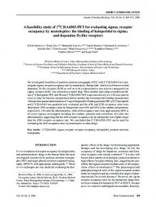
With k = 1, the frequency sidebands (1 ± 2 s) f of the fundamental are very commonly used to detect broken bar faults, and is the method used in this study as well. EXPERIMENTAL RESULTS A 3-phase squirrel cage induction motor is used in the experiments. The rotors for the healthy and faulty cases are similar, except that 4 out of 44 bars are broken in the faulty machine. The machine is run under full-load and the line current data is collected using a PC-based data acquisition system. The captured waveforms of the healthy motor and the faulty motor are shown in Figs. 1(a) and (b) respectively. 15
10
Current (A)
5
0
-5
-10
-15 0
20
40
60
80
100 120 Sample
140
160
180
200
Fig. 1 (a): Line current of healthy motor. It is seen that there is no noticeable difference between the two waveforms. It is therefore not possible to diagnose a broken bar fault using the time-domain data. However, the spectral components of the line currents allow us to draw some conclusions about the state of the machine. We need to perform a Fast Fourier Transform (FFT) on the data to estimate the spectral components around the fundamental of the current. As discussed in the previous section, the sidebands of interest in the signal are closely spaced to the
Current (A)
interacts with the fundamental air-gap flux to produce speed ripple at 2sf . This phenomenon gives rise to sequence of additional current components at frequencies given by f b = (1 ± 2 ks) f , (3) k=1, 2, 3, ...
5
0
-5
-10
-15 0
20
40
60
80
100 120 Sample
140
160
180
200
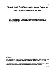
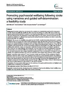
Fig. 1(b): Line current of faulty motor. fundamental and can be observed only with a fine resolution in the frequency domain. With a full load slip of 0.04, the sidebands corresponding to k=1 in (3) are spaced about 5Hz away from the fundamental. This necessitates performing an FFT on a large number of samples or decreasing the sampling frequency. The sampling frequency is 3840Hz. A reduction in this frequency will cause aliasing because of the high-frequency components present in the signal. (Some of these components are due to slot harmonics and are not of interest to us in this study). The signal captured at this frequency is low-pass filtered and then downsampled to reduce the sampling frequency to 960Hz. With the new signal at the reduced sampling frequency, it is possible to reduce the number of samples for computing the FFT and still observe the sidebands of interest. An 8172-point FFT is performed, which gives a frequency resolution of 960/8172 = 0.12Hz. The results of the FFT for the healthy motor and the faulty motor are shown in Figs. 2(a) and (b) respectively. The spectral components have been scaled by the amplitude of the fundamental at 60Hz. The two sidebands at 55Hz and 65Hz are clearly distinguishable in the FFT of the faulty motor. This forms the basis of DSP-based broken rotor bar detection in induction motors. IMPLEMENTATION ISSUES The implementation consists of the following steps: 1. Data Acquisition: Sampling the input and storing it in memory is taken care of by the ADC and the timers in the EV of the ‘F240. The line current sensor output has to be rectified to match the 0-5V input of the ADC. 2. Decimation: The captured data is filtered to prevent aliasing, and then down-sampled to
0 -10 -20
0 -10 -20 -30 Magnitude (dB)
reduce the number of computations needed for the FFT. 3. FFT computation: The FFT is performed on the stored data values and the results are stored in memory. 4. Fault detection and indication: This routine checks the magnitude of the spectral components at the sideband frequencies to determine whether a fault exists. In case a fault is detected, a visual indication is provided to the user so that remedial measures can be taken. The main issues in implementing the FFT in the TMS320F240 are computation time, memory storage requirements, and errors due to fixed-point computations and finite register length. A discussion of some commonly used algorithms for implementing the FFT in DSPs can be found in [2,3,4]. In a typical DSP-based induction motor drive, the main function of the DSP controller would be to implement the routines to control the speed or torque of the motor, such as field-oriented control or vector control. Fault diagnosis is expected to be included as a housekeeping feature, and this routine is likely to be executed only once a day or even less frequently. Hence the computation time is not really a concern. The memory required for FFT computation is directly proportional to the number of samples. External RAM can supplement the on-chip memory for this purpose. This slows down the computation due to memory access times, but this is not perceived to be a problem.
-40 -50 -60 -70 -80 -90 -100 50
52
54
56
58
60 62 Frequency
64
66
68
70
Fig. 2(b): FFT of faulty motor line current. As can be noticed from the FFT of the faulty motor’s current, the difference between the amplitudes of the sidebands and the adjacent frequency components is extremely low (1%) and the computation must be accurate enough to show this up. This is expected to be the main issue in the fixed-point implementation of this scheme. A 128point FFT routine developed by TI [3] was initially used to distinguish between the healthy and faulty machine spectrums, but fault detection was not possible because of poor resolution. The same algorithm can however be extended to a larger number of samples to improve the resolution. CONCLUSION The possibility of including fault diagnosis as a feature in TMS320F240 DSP controller based induction motor drives has been explored in this paper. The nature of the fault to be detected was discussed, followed by the method to be used for diagnosis. The main issues to be addressed in such an implementation have also been identified.
Magnitude (dB)
-30
REFERENCES
-40
[1]
-50 -60 -70 -80
[2]
-90 -100 50
52
54
56
58
60 62 Frequency
64
66
68
Fig. 2(a): FFT of healthy motor line current.
70
[3]
[4]
Subhasis Nandi, RajMohan Bharadwaj, Hamid A. Toliyat, Alexander G. Parlos, “Study of Three Phase Induction Motors with Incipient Rotor Cage Faults Under Different Supply Conditions,” To be presented at the IAS Annual Meeting, Oct. ’99. “Implementing Fast Fourier Transform Algorithms of Real-Valued Sequences with the TMS320 DSP Family,” TI Application Report: SPRA291. “Implementing a Spectrum Analyzer Using a 128 Point FFT and the TMS320F240 EVM,” TI Application Report: SPRA417. “An Implementation of FFT, DCT and other transforms on the TMS320C30,” TI Application Report: SPRA113.